


The short answer is, “yes”– after all, people are already doing it. But the reality is that we could do much, much better. Some people think that we do need a separate “SourceForge for hardware.” That’s hard to say. But it is the case– perhaps against conventional wisdom –that existing tools can be used, today, for meaningful hardware version control.
It’s certainly possible to take any old binary file (say from a CAD program), and store it in a version control system. This is, in fact, how many of today’s open source hardware projects are managed. However, a “diff” (direct file comparison) to see what’s changed between two versions of a given file is all but meaningless. For design files in plain-text (“ascii”) file formats, such as Inkscape‘s SVG or KiCad‘s .brd, a diff is possible and is in principle meaningful, but it is usually all but useless in practice, because CAD is a graphical sport, and we need to treat it like graphics. An example: Suppose that you found the following snippet in the difference between two SVG files:
 <path
       sodipodi:type="arc"
       style="fill:#ff00ff;fill-opacity:1;stroke:#ffa6a6;stroke-width:0.18000001;stroke-linecap:round;stroke-linejoin:round;stroke-miterlimit:4;stroke-opacity:1;stroke-dasharray:none;stroke-dashoffset:0"
       id="path2816"
       sodipodi:cx="237.14285"
       sodipodi:cy="328.07648"
       sodipodi:rx="160"
       sodipodi:ry="84.285713"
       d="m 397.14285,328.07648 a 160,84.285713 0 1 1 -319.999997,0 160,84.285713 0 1 1 319.999997,0 z" />
You probably wouldn’t recognize that (at least not quickly) as a big magenta ellipse. While it’s perfectly legible as source code, a diff result like this would be all but useless in practice.
The obvious solution, is to add in some visual diffs in order to make sense of changes between design files. On the bright side, making these is remarkably straightforward, and– with a little bit of effort –practically supported by existing version control systems.
In what follows, we’ll walk through some examples of visual diffs– with bitmaps and PDF files –and discuss what you can do to help make version control work better for CAD files, and to make CAD files better for version control.
Visual Diffs: A set of concrete examples
CAD programs are, at their hearts, graphic design programs. We can begin with any type of data that can be abstracted to a meaningful 2D image, whether that’s a set of architectural blueprints, a circuit diagram, the physical layout of a layer of an integrated circuit, or plan views of a 3D object.
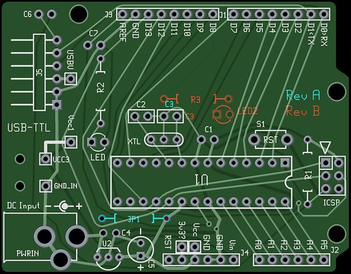
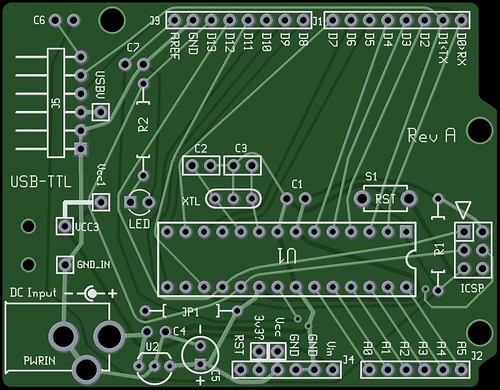
To put it on a firm footing, let’s suppose that we were going to revise the design of the Diavolino, an electronic circuit. Let’s suppose that we download and open up two versions of the design file, “Rev A” and “Rev B,” and open them up.
you can learn more about gEDA here.)
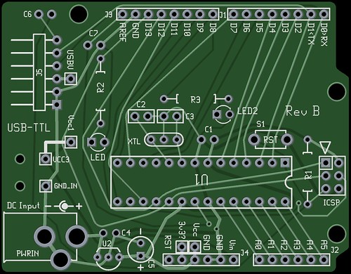
Now, here is the second version, “Rev B,” where we’ve made several changes:
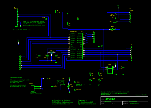 Can you see the changes? Probably not easily. (Click here to see this in full size.)
This is a case where a visual diff could help immensely. There are any number of good ways to go about doing this. One straightforward way to do this “manually” is to use the ImageMagick utilities. Starting with monochrome PDF images of the two diagrams, we use the ImageMagick convert utility to make matching PNG files, and then use the ImageMagick composite utility to stack the two images:
convert -density 150x150 +antialias -negate diavolinoA.pdf diaschemA.png
convert -density 150x150 +antialias -negate diavolinoB.pdf diaschemB.png
composite -stereo 0 diaschemA.png diaschemB.png compdiff.png
Here is the result:
 Now, the changes stick out like a sore thumb: We’ve deleted a jumper wire, and added another resistor and LED. We’ve also moved a power supply connection point and added a revision note without affecting the circuit electrically.
To get the color shifts, we’ve used ImageMagick’s stereo option, which is normally used to create red-green anaglyphs. Bonus feature, versus other methods of color-coding changes: If you are colorblind, you can use readily-available and inexpensive red-green 3D glasses as “corrective lenses” to see the changes in your diff.
(Click here to see this in full size– at much higher quality.) You can also use a direct, graphical PDF diff program to compare two PDF files:
Next, let’s look at the circuit board layout for the Diavolino, in the two revisions:
convert -colorspace gray diavolinoA.png diavolinoA.png

convert -colorspace gray diavolinoB.png diavolinoB.png

composite -stereo 0 diavolinoA.png diavolinoB.png pcbdiff.png
(The first two lines of code convert the two files to grayscale– this isn’t absolutely necessary, but the green color does make it harder to see changes.)
Here is the result:
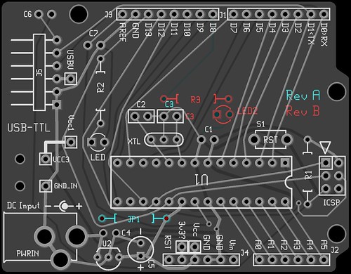 You can see the now-missing jumper (lower left) and the addition of the resistor and LED near the center. The change in revision labels act much like commit comments, in this context.
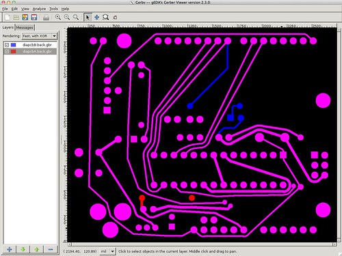
While this “photo” view is helpful to see components and labels, one thing that is not easy to see is that the traces on the circuit board have changed as well. To look at the copper layer changes, we can perform a layer-by-layer diff analysis, directly on the Gerber files.
gEDA PCB is quite scriptable, and can generate gerber file output directly from the command line. We can then call gerbv, the gEDA Gerber file viewer to look at the differences:
You can see the now-missing jumper (lower left) and the addition of the resistor and LED near the center. The change in revision labels act much like commit comments, in this context.
While this “photo” view is helpful to see components and labels, one thing that is not easy to see is that the traces on the circuit board have changed as well. To look at the copper layer changes, we can perform a layer-by-layer diff analysis, directly on the Gerber files.
gEDA PCB is quite scriptable, and can generate gerber file output directly from the command line. We can then call gerbv, the gEDA Gerber file viewer to look at the differences:
pcb -x gerber --gerberfile diapcbA diavolinoA.pcb

pcb -x gerber --gerberfile diapcbB diavolinoB.pcb

gerbv *.back.gbr -a --background=#000000 --foreground=#ff0000 --foreground=#0000ff
Automatic visual diffs, with the help of version control
Thus far, we’ve been over a number of different ways to look at hardware changes, both in a PDF schematic, in Gerber files, and in PNG files. All of these are essentially “manual” methods, best for comparing two versions of a file on your own computer. But what if you want to do this on a regular basis, with every commit of your project? It turns out that this is all actually much easier than we’ve been letting on. GitHub now automatically supports visual diffs for image files included in commits. What this means is that if you (as a designer) generate and include an up-to-date PNG version of your schematic and layout in every version and commit there, you will also automatically generate a matching visual-diff history of the project. This is potentially huge — if the open source hardware community will step up to the plate and take advantage of it. Closing the loop, so to speak, and making truly efficient use of version control tools for hardware will require several more things. Most importantly, we need to be able to visually manage merge operations and resolve merge conflicts. For this to happen, we need CAD files to increasingly use plain-text (ascii) file formats, which are potentially capable of being sensibly merged. We’ll also need developers of project management software to become aware of these kinds of needs for hardware project, and to consider ways to automatically generate the necessary image files from the original CAD data.What can you do to help?
1. If you are designing project management or source control software:
Work to include ways to produce visual diffs, for as many formats as possible. Ideally, figure out ways to automatically generate the visual representation from the primary CAD data. Can your project hosting site show visual diffs between two revisions of an Altium or Solidworks file? At a minimum, can you produce graphical diffs between versions of PDF or Gerber files? For many open source design tools, there are scriptable (command line) tools that can be run on unix-like web servers, to automatically generate image files and PDFs from CAD data. Make use of these, and help encourage software companies and coders on related projects to support additional tools like these. Separately, merge operations are already possible for design files that are in ascii (i.e., non-binary) file formats. We need to be able to resolve merge conflicts, by looking at the graphical changes that result from including or not including certain changes in the files. This is a new need for version control software: to select and approve changes based on a visual, not text, differences.2. If you are designing open source hardware:
Take advantage of these tools, and help others to do the same. If you host projects at Github, it’s easy for anyone to use their visual diff feature, provided that you provided data in the right formats. With each revision and commit, upload not just your new CAD file, but also (ideally) both PNG and PDF format output– for example plan views in solid CAD or schematic diagrams for electronics. Most CAD systems provide ways to produce this kind of output in a reasonably automatic and fully consistent format; learn how, and make it a habit. Committing these at the same time as your CAD files– and making those visual diffs possible –makes source control truly meaningful, even for designs using proprietary file formats. Depending on context, it may be just as useful to also have each commit include other standard output formats, such as STL or IGES (for mechanical design) or Gerber (for electronics). As project hosting and source control for hardware evolves, visual diff tools for standard output formats like these will come along for the ride. They’ll come along faster if there’s a critical mass of commit data out there that can be viewed with those tools. 3. If you are writing or maintaining CAD software (or if you know how to program and would get to get involved): The open source hardware community needs your help. Ideally, in the long run,there will be a wide selection of CAD software, everywhere on the spectrum from proprietary to free and open source. There are any number of open source CAD packages in development, and many of them could use additional hands. In the short term, the community would benefit greatly from (A) more software supporting open file formats and/or (B) command-line tools to generate usable output data (PNG, PDF, Gerber, STL, and the like) from the original design files. Having these tools– and thereby giving users the ability to really take advantage of many features of source control for hardware –would be a great market advantage for any CAD package. Going beyond this, native support for “ascii” file formats (as opposed to binary) is a “must-have” feature for supporting merge operations in version control. Afterword As we fall into the second category, designers of open source hardware, we’ll be doing our part to help. We’ll soon begin migrating our hardware projects to github, to take advantage of the new visual diff tools there. We’ll also greatly expand the number of files and formats that we generate and support. Source control is real and possible, today, for open source hardware. If we work together, it can only get better. We hope that you’ll join us. Further reading
http://www.instructables.com/id/Visualizing-EAGLE-Edits-with-a-Gerber-Viewer/ by westfw at Instructables.- Comparing images and creating image diffs by Jeff Kreeftmeijer

Hey,
There is a great part of git which includes ‘diff hooks’. Those allow git to run a program or script when they match a file extension while doing a check-in, or check-out. That is to say, you can write a quick bash script that will be called when ‘git diff’ hits a file with a specific file extension.
I will probably be building this (for use in my work and side projects) now that I see how easy it is to do that overlay trick. I had considered doing this before but I wasn’t sure how to build the visualization. I think some ImageMagic and some bash scripting could really do the trick.
How about using git difftool that allows us to use external diff programs?
We can have it call a small wrapper that in turn does the imagemagic stuff if the file is in a supported format, if not, it can just pass the arguments on to the external diff program.
Github itself has image diffs
https://github.com/blog/817-behold-image-view-modes
You might want to, you know, *read the article* before commenting….
Windell H. Oskay
drwho(at)evilmadscientist.com
http://www.evilmadscientist.com/
Nice post. I hope everyone trying to create "THE" repository for open source hardware is paying attention to these types of issues :).
I wonder how hard it would be to show rearrangement etc. (component was moved from point A to point B). Seems like it would be doable.
Regular text diff tools don’t attempt to show movement of a block of text. Detecting movements in text is _much_ easier than doing it in images. And programmers have been doing without that feature since forever. So I don’t think that open hardware designers should worry about it much before programmers get it working in text diff tools.
Hmm. Part of the problem is that the "design files" for open hardware are typically NOT image files. but relatively obscure and frequently proprietary "design files" from which MAYBE you can derive images. It’d be nice to convince SCCS tools to be able to derive images using arbitrary complex methods (perhaps running locally on your computer) "before" the compare steps. Or maybe CAD vendors should provide "cloud" services for translating their CAD files into an image file in some sort of standard way…
I don’t think it would be a particularly good thing if the image files associated with a design become overly emphasized. Making sure your images are in-sync with the actual design is yet another step; yet another place for errors to creep in.
OTTH, maybe this just gets put into the commit tools…
Thanks for the tips! I put your techniques into script form and submitted patches to get them added to gEDA. The Launchpad bugs are https://bugs.launchpad.net/geda/+bug/698744 and https://bugs.launchpad.net/bugs/864770 .
Check out http://www.solderpad.com/ as a potential spot for hosting open hardware projects.
This site builds on git using a .solderpad directory to display things like the schematic, board image and bill of materials.
It shouldn’t be too difficult for them to integrate ‘visual diff’.
I just put together some git hook scripts that automatically creates .png’s of changed .sch and .pcb files in a git repository. You can get them here: https://github.com/BenBergman/.git_hooks and they are designed to work with git-hooks, found here: https://github.com/icefox/git-hooks (though they could easily be used directly in .git/hooks with some minor modifications). Feedback is always welcome. :)