Tag Archives: AVR

Basics: AVR Target Boards and Arduino Compatibility

Diavolino
Gary writes:

I have fallen in love with your Diavolinos – thank you!
My question: does the “Simple target board” allow for the 6-pin FTDI Friend hookup to upload sketches? This is quick and easy with the Diavolino. I’m new to reading circuits and stuff, and I cannot tell looking at the target board. It says to use in-system programmer, but I prefer to not buy another interface. Thanks!

Excellent question! It is certainly possible, but not as quick and easy.  Both the Diavolino and our ATmegaXX8 target boards boards use the same chip, usually the ATmega328P.  But, one might say that our ATmegaXX8 board is a simple AVR target board optimized for use with an AVR ISP programmer (like the USBtinyISP), whereas the Diavolino is a simple target board optimized for use with the FTDI interface.

XX8 Target Board

Versus a “bare” target board (with just the chip and power), there are four things that you would normally add, in order to use the FTDI interface to upload a sketch from within the Arduino environment:

Continue reading Basics: AVR Target Boards and Arduino Compatibility

Maker Faire New York 2013

Maker Faire New York 2013 Logo

Maker Faire New York is almost here! We’ll be in the Atmel booth, showing a few of our favorite AVR projects, including Meggy Jr RGBArt Controller, and Octolively.

We’ll also be bringing our new Three Fives timer (despite it not having any microcontrollers). The schedule for the fair is up, so if you’re in the area, you can start planning your weekend now.

The Art Controller

Art Controller

Today we’re releasing a new open source kit: A stand-alone, microcontroller-driven relay module called the Art Controller.

The Art Controller project was originally suggested by our friends (and Maker Faire regulars), San Francisco Bay Area kinetic artists Christopher T. Palmer and Nemo Gould.  Amongst other things that they build are amazing mechanical sculptures that need to run for a little while after a visitor presses a button or inserts a coin into the slot.

The long-established solution for driving electronic artwork (along with many similar endeavors) is to use a timer relay module; a little stand-alone board with a relay controlled by a timer.  There are several types of these: fancy programmable modules, bulletproof industrial types, and simple low-cost boards with a 555 timer and a pot that you turn to adjust the delay.  As we understand it, Christopher and Nemo go through the latter type like jellybeans.  But, what they realized that they really wanted was something just like that, except that you could reprogram it if you wanted to.

Art Controller

Hence the Art Controller.   It’s a low cost stand-alone relay module, with an on-board AVR microcontroller, an ATtiny2313, that manages the timing and I/O.

It can be used as a replacement for one of those basic 555-based relay boards, but it’s considerably more flexible in terms of timing range and functionality:

  • The timing is adjusted with an 8-position DIP switch, rather than a knob.  This cuts down on guess-and-check, but also gives a huge range. With those 8 little switches, you can select times from 1 second to 31 hours. (The ranges are 1-31 seconds, minutes, or hours, plus a few intermediate ranges.)
  • It can work as a one-shot timer or a continuously repeating timer.
  • There’s an option to trigger automatically upon turn-on (reset).
  • There’s a separate cancel input, so you can build a “STOP” button.
  • There’s an option to cancel a trigger if you push the “START” button a second time.

It comes preprogrammed, and all of those adjustments can be done with switches and wiring— handy if solder is your favorite programming language —so no computer or programming are actually required to get that far.

But, when that’s not enough, the on-board microcontroller can be reprogrammed in situ (using the board’s AVR ISP programming header) to handle the most specialized applications, potentially taking advantage of up to 16 free digital I/O pins.

And that’s pretty neat. 

Art Controller

Beyond the obvious applications in DIY projects, automation, and controlling art projects, we think that this is also going to be a fantastic relay board for education. It starts out as a (well-designed) simple function timer relay board, but can optionally transition to a full-on microcontroller development board when you’re ready for it.

So that’s the Art Controller in a nutshell: a versatile, easy to use, low-cost relay board that you can reprogram if you want to.

There’s plenty more detail on our product page: The Art Controller at Evil Mad Science.

And, special thanks to Christopher T. Palmer and Nemo Gould for a great project idea!


This post is included in our Halloween Project Archive, where you can find ideas for props, decor, and more.

Basics: Blink an LED with an AVR

AVR Blink Blog Post

Getting an AVR to blink might seem like an incredibly difficult task compared to the usual Arduino blink, but it really isn’t! In this post we will be uploading a basic blink example to an ATtiny2313. This is perfect for projects where using an Arduino would be over the top. So let’s get started!

Continue reading Basics: Blink an LED with an AVR

Halloween Projects from Evil Mad Scientist Laboratories

The Great Evil Mad Scientist Laboratories Halloween Project Archive!

Halloween is one of our favorite holidays, and our collection of Halloween projects continues to grow. Every fall we update it to include our latest projects for the season. In the list that follows, we’ve organized dozens of our Halloween projects into categories: costumes, pumpkins, decor and food.

Last updated: 10/2019.

Continue reading Halloween Projects from Evil Mad Scientist Laboratories

ISP Shield Kit

ISP Shield

The Evil Mad Science ISP Shield is a new open source hardware kit that we’re releasing today.

It lets you use your Arduino (or shield-compatible clone, such as the Diavolino) as an AVR ISP programmer, for example to burn bootloaders onto “raw” AVR chips, directly within the Arduino programming environment, either in the provided ZIF socket or on an external target board.

You can read more about this process here.

The circuit is designed to be compatible with the “Arduino as ISP” option in recent versions of the Arduino IDE. It is based on a number of prior hardware implementations, most closely the version by Andre Knoerig at Fritzing.

Complete documentation, including assembly instructions, design files, and basic usage information is available on the Evil Mad Science Wiki.

The 4313 has landed.

ATtiny4313-PU

One of our all-time favorite chips is the ATtiny2313.

It’s a little 20-pin AVR microcontroller that we’ve used in dozens of projects, including our high tech holiday decorations, some of our coolest pumpkins, our (digital) Larson Scanner, and some 
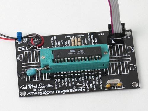
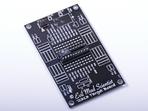
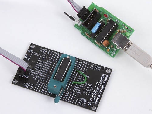
wacky papercraft— to name a few. It’s one of those few chips that we used often enough to justify a custom
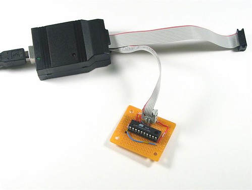
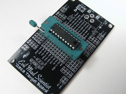
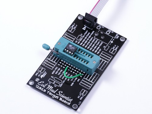
 breakout board.

But… if there’s one thing that the ‘2313 is short on, it’s memory. With 2 kB of flash (program) memory and 128 
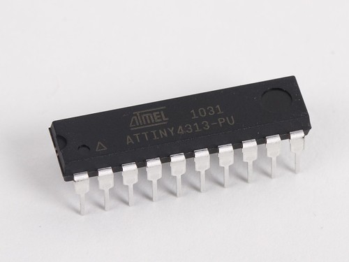
bytes of RAM, it’s perfect for tiny single-purpose projects. But, it’s oh-so-easy to run up against that memory limit. And, that’s why we were so excited when Atmel began to announce their then-forthcoming ATtiny4313 in late 2009.

Unfortunately, it’s often a long delay between when a chip is announced and when it’s actually available through distribution. Sample quantities have been floating around for half a year or so, but– and 
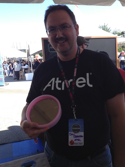
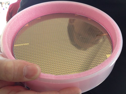
finally— a big box showed up in the mail, and so here they are.

4313 - 3

Now, programming it. There are very few changes between the ‘2313 and ‘4313. Mainly, it’s what you’d expect: memory sizes (Flash, SRAM, EEPROM are all doubled), and the device signature is different.

Recent versions of AVR-GCC already support the ‘4313, and so it’s relatively straightforward to recompile an existing program (say, the Larson scanner firmware) to run on the ‘4313. There are some minor inconsistencies between the “io.h” header files for the two chips, and those inconsistencies can cause compiling to fail. For example, the register name “WDTCSR” (for watchdog control register) works on the ‘2313, but the ‘4313 io.h file lists that same register name as “WDTCR.” So, if you run into a place where AVR-GCC is confused after switching chips, you might be able to solve the issue by comparing that register name in the “io.h” files for the two chips.

Now, for programming the chip with avrdude, things are slightly more complicated. Avrdude does not yet natively support the ‘4313, but fortunately, you can add the new chip definition by editing the avrdude.conf file on your system. (On my Mac, where I use Crosspack as the AVR toolchain, I found that file at /usr/local/CrossPack-AVR/etc/avrdude.conf ) The ‘4313 code block can be added right below the ‘2313 code block, and you can download that code block here (via this mailing list post). So, a couple of steps, but works like a charm.

There aren’t a whole lot of these to go around right now, but we’ve put some of our ‘4313 chips into little dev kits that you can pick up at our store. Let’s see how long they last. ;)

AVR Basics: Reading (and writing) flash contents

Programming on a target board

From our forums comes this interesting question:

   “Is it possible to download the contents of an ATmega168/328, essentially backing it up so that it can somehow be restored later?

For example: Let’s say I have lost the source code to a very useful program currently residing on a 328, but I need to flash it with a different sketch temporarily, then restore that original sketch. This would be useful in the case that the chip was soldered directly onto a board – a big mess to try to replace.
Is this possible in some way, perhaps by altering an ISP programmer?”

The answer is that yes indeed, it is possible– with a couple of exceptions that are worth mentioning. And on occasion, it’s even very useful. Continue reading AVR Basics: Reading (and writing) flash contents

AVR programming trick: Sharing target boards

2313-25 (plain socket)

This week, Brad wrote in with an interesting question: Can you program the ATtiny25 on one of our ‘tiny2313 target boards? And the answer is yes: you can, with just a trivial modification.

Okay, back up– a little context here. The ATtiny25 and the ATtiny2313 are examples of AVR microcontrollers, the little brains that power many of our projects.
To program these chips, we use a usbtinyisp programmer, hooked up to a minimalist target board.

USBtinyISP & simple target

The target board basically provides a programming header that’s hooked up to the right pins of the chip, plus some way to power the chip– often through the programmer itself.

After hand-wiring up one too many minimalist ‘2313 boards like that, we also made a printed circuit board version of the ‘2313 target board. Normally, it looks something like this, with an ATtiny2313 in a ZIF socket:
2313Card - 4

But, back to the question. The ATtiny25, ATtiny45, and ATtiny85 are a family of 8-pin AVR microcontrollers that are not pin compatible with the ‘2313. However, at only 8 pins instead of 20 pins, they’ll definitely fit in the socket… somewhere.

Looking at the datasheets and pinouts for the the ’45, ‘2313 (and the ‘168 that we also have a target board for), we can identify the lines used for programming: MISO, MOSI, SCK, and RESET:


The chips also need power and ground connections to be programmed, of course. Now if you notice, the connections for the ‘2313 and ’45 are very similar– in fact, almost identical if you line the chip up so that pin 1 goes where pin 1 of the ‘2313 normally would. The one remaining difference is that there’s no ground connection to pin 4 of the ‘2313.

2313-25 (fixed up)

So, adding a wire from ground– pin 10 of the ‘2313 –to pin 4 of the smaller chip (an ATtiny25 in our photo), and lining up pin 1 to pin 1, we’re ready to go. And yes, it works like a charm.
If you do use this method, there are a few (possibly obvious) things worth noting:


  • You need to be careful to line up pin 1 of the chip to pin 1 of the socket.
  • Be careful if or when you put a ‘2313 chip back in the socket. It will draw a lot of current if you set pin 4’s to a high output level– it’s shorted to ground. (Better: If you want to go back and forth, use a switch, not a wire.)
  • Keep in mind that the pin labels on the target board are for the ‘2313, not the ’85.

Going one step further, you could also potentially program the ’25/’45/’85 from the ‘168 target board: it only takes a couple more wires. To do so, line up pin 1 of the ’25 to pin 9 of the ‘168. Add two wires this time, from board-reset to chip-reset, and from board-ground to chip-ground. You’ll also need to connect AVCC (analog power supply) to VCC. A little more work, yes, but still a good hack.