


Rember the silent caterpillar drive from the movie The Hunt for Red October? The caterpillar drive was a fictional magnetohydrodynamic propulsion system. Magnetohydrodynamic (MHD) propulsion is a means of using electrical current, instead of a noisy propeller, to push a ship through the water.
Surprisingly enough, a working example of this futuristic drive system is quite easy to build. Assuming that you’ve got the materials handy, you can build one in about a minute. You’ll need a strong magnet, two pieces of thick copper wire, a little dish of warm water, salt and pepper, and a regular battery.
[This is the first in a series of three articles on building simple magnetohydrodynamic (MHD) propulsion systems.]
Ready to build one? Let’s get started:
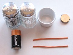
The ingredients: Salt and pepper, a little dish that we’ll put water in, two pieces of thick-gauge copper wire, a battery (just about any type), and a strong magnet.Use thick copper wire here because thin wire will get very hot and burn your fingers. The best type of magnet to use is a neodymium disk magnet, but just about any strong magnet will work. Note that magnets from hard drives are not the best choice because they usually have both poles on the same face of the magnet.
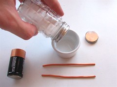

Pour a little water in the dish and stir in some salt and pepper. The ideal depth of the water is about 1/4″, but it’s not critical (it’s about a half-inch deep in the photo). Mix up the water so that the pepper doesn’t all float on the top. Set the dish of water on top of your magnet.
Why salt and pepper? MHD propulsion relies on conducting current through water. Water is normally a poor conductor, but salt water is a great conductor. Adding the final dash of pepper makes it so that you can see when the water moves. =)
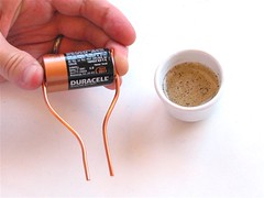
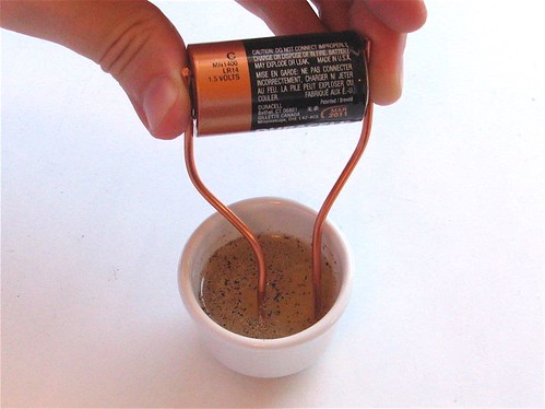
Bend the wires as shown, so that when you hold the wires against the battery, the ends are a couple of centimeters apart. Don’t let the two wires touch!
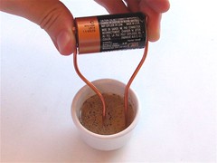
Stick the ends of the wires into the water. Ideally, put one wire in the center and one against the edge. Assuming that your battery isn’t dead, the water will begin to move between the two wires. If you flip the magnet up side down or reverse the direction of current, it will reverse the direction that the water moves.
Important safety tip: You’re dealing with electricity and salt water; use some common sense. Small quantities of potentially poisonous and/or explosive gasses may bubble out of the water; don’t try and scale this up unless you really know what you’re doing. Besides that, copper wires can have pointy ends and magnets can pinch you.
Short movie (43 s), demonstrating this magnetohydrodynamic propulsion system (Alternate youtube link here.):
OK, so how the bleep does it work?
Last month we showed how to make a homopolar motor, which is the oldest and simplest type of electric motor. In the example motor that we made there, a magnet hanging on a screw is spun up to high speed. Here, we have constructed a magnetohydrodynamic “motor” that spins salt water. The dynamics of these two systems are exactly equivalent; both are fundamentally examples of homopolar motors.Michael Faraday‘s original 1821 homopolar motor was somewhere between these two examples. Rather than using a rotating magnet, he used a pool of liquid mercury (an excellent conductor) sitting atop a magnet. In his Popular Science column this month, Theodore Gray recreated that original motor, using a genuine pool of mercury. Among the different designs that have evolved from that original are those (like the one with the screw) that rotate a mechanical object, but also the magnetohydrodynamic version, which can propel a ship through the ocean.
Sure, you say, but how does it work? Let’s back up for a moment and first look at how the (rigid) mechanical homopolar motor works. For the sake of concreteness, we’ll use the example of the motor that we wrote about previously.

A simple, “rigid” homopolar motor. Electrical current flows in the direction indicated by the purple arrows: from the bottom end of the battery, down the screw, through the magnet, up the wire, and back to the top of the battery.(By the way, I made these drawings in POV-Ray. Someday, I’ll put the rest of my tutorial on line.)

Zooming in on the magnet, we now illustrate the magnetic field lines (blue) sticking up through the magnet. The magnetic field above the magnet essentially points upwards. Again, the direction of current flow is given by the purple arrows. The horizontal current arrow is the important one. The electric charges moving through the magnet feel a Lorentz force whose strength is determined by the angle between the magnetic field orientation and the direction of current flow; the force is strongest if they are 90 degrees apart. The direction of the resulting force is perpendicular to those two directions.For the currents that flow in the screw and wire, the forces are minimal since the current direction is parallel to that of the magnetic field. However, there is a substantial force on the electric charges that flow horizontally through the magnet, at 90 degrees to the
(vertical) magnetic field orientation. Thus, a force (green arrow) is generated in the third direction, which gives rise to the magnet spinning.

In the magnetohydrodynamic motor, we place a container of conductive salt water directly above the magnet. The situation is essentially the same as in the previous illustration; the only significant force arises where the electric current flows horizontally, that is, in the direction perpendicular to the magnetic field. Since the current is now flowing through the water, rather than the magnet, the resulting Lorentz force is applied to the water, not to the magnet. And indeed, the water begins to spin.

It could be a problem with the liquid helium, or the superconductors!
(always wanted to say that!) –u37566
This is awesome! I’m going to be making a motor for a science fair at school, but couldn’t give an explanation for how the homopolar motor worked. This site is the only one I could find, and understand. Thanks for the explanation.
right said. you can see this everywhere but no one explains how it works. thousand thanks to you for explaining the stuff
Could this model be reversed to generate electricity from a water movement?
use baking soda instead of salt,no poison gas that way.not like your gonna create much anyway with this, but is cool.
This is a comment to “OK, so how the bleep does it work?” section, specifically to the statement The dynamics of these two systems are exactly equivalent. I have a problem with applying the mechanism described in the section to the case of magnet and screw.
Yes, the magnet applies Lorentz force to the current inside itself, but the current sure applies the reaction force on the magnet (as in Newton’s 3rd law, action and reaction). And because the current is INSIDE the magnet, these two forces are internal forces and cannot cause rotation. If they caused, it would be a violation of conservation of angular momentum. So, there should be different mechanism explaining this experiment.
I agree, mechanism of homopolar motor is totally different from conventional DC motors. We used to think that the electromagnet rotor applies force on the stator magnets and since they are anchored to the case of the motor, stator rotates against the force which is linked through the physical bodies of the magnets. But in homopolar motor, it seems the body rotates against the MAGNETIC FIELD, not against to a physically static magnet relative to us. If things taught at schools are true, then the forces arise here would sum to zero. But it is not, as you can see, so the magnet only provides field here, it does not need to push somewhere physically to
turn the body. It pushes (or pulls) something invisible what we call that Magnetic Field. If we think the electric particles are the ones moving by Lorentz Force, then someone would assume it is this moving particles drag the magnet body by means of a friction…
I agree, Newton’s third law "Every action has an equal and opposite reaction" means that the force on the moving charge has a reaction on the magnet. Since in this part of the circuit the magnet is the conductor which is a single solid body, these equal and opposite (torques) must cancel.
However, the magnetic field curves round and is orthogonal to the vertical part of the wire which is fixed, so a force is exerted by the magnet on the wire. The reaction to this force is a force exerted on the magnet. This is off-axis so forms a component of a torque (the top of the screw being constrained within the button of the battery). This reactive torque causes the magnet (and screw) to spin.
In the case of the hydrodynamic motor, the fluid and magnet are not joined in one solid body, so the magnet does apply a force to the conductor fluid and the explanation is correct.
Visualisation is great! But the direction of the magnetic field is wrong.
If you denote the magnet have it’s north pole down and south pole is up
then the drawing will be ok :)
Well, the conductive water will release oxygen and hydrogen under the battery’s electricity. I have another alternative. I’ll tell you when its ready!
Uh, current always flows from negative to positive in a battery. Your drawing shows it going to opposite way.
Technically, "current" does flow from positive to negative. Electrons travel from negative to positive, but the term "current" is normally used to describe the "flow of positivity" in the opposite direction to those electrons. Why is beyond me.
Simply convention – electricity was harnessed before electrons were known. Current was assumed to travel from positive to negative. Later when it was discovered that electricity was a flow of electrons, we realized that the actual electrons move from negative to positive.
This is why electrons have negative charge. If the original definition of current was in the other direction, then electrons would have a positive charge.
Actually, it is all point of view. Electrons flow negative to positive. Holes flow positive to negative. Electronic circuits make sense when looking at electron flow. Semiconductors and Integrated Circuit design require the flow of holes.
Inside the water no. Because the magnetic filed position depend from the electrons flux, not the water flux. And the electrons flux don’t change with the water flux.
However, we can produce eletricity from water falling(only step falling) or water waves. Because, at those cases, the water is sorrounded by ar and the electrons travel only in water. The water moviment cause magnetic field moviment too, with a coil that moviment can generate eletricity.
sorry my bad english.
If my understanding is correct yes you can it is essentially the same as a homopolar motor and there have been homopolar generators developed. Not that it would be efficient but it would essentially be the same as turning the homopolar motor to get electricity so yes you could generate electricity but not much.
2NaCl(aq) + 2H2O(l) —electrolysis—> H2(g) + 2NaOH(aq) + Cl2(g).
Then:
Cl2(g) + 2NaOH(aq) —-> NaCl(aq) + NaClO(aq) + H2O(l).
Hey, I´m doing this proyect for a science fair, but the water doesn´t spin, it just oxydates the cable, and I would like to know what am I doing wrong, if you could please help me, thanks.
Sorry for my english.
Did you place the magnet below the cup?
You need a magnetic field to get the conducting fater in motion
Yes i did, let me tell you the material that I used: salt, pepper, water, a battery of 1.5V, two thick copper wire, and a magnet (black color magnet). How do you know the difference between a strong magnet and a weak magnet? Because the magnet that I´m using is the one that is in the refrigerator.
A standard refrigerator magnet is nowhere near strong enough for this demonstration to work properly. Also, many fridge magnets have inappropriate field configurations– it may be more than just a strength issue. Try to find some moderate size neodymium disc magnets– that’s the type that you need.
Windell H. Oskay
drwho(at)evilmadscientist.com
http://www.evilmadscientist.com/
I just posted a question. I was unable to get this to work. The only thing that is different is the thickness of my copper wire. Could that affect it???
Thanks!
The exposed area of the wires will potentially affect how much current flows through the water. You could try making some larger electrodes from copper coins or similar to see if that helps.
So is this the accepted explanation for the effect, or does the original one (given by Windell in the writeup) still apply? I.e., I am confused (and I’m not sure I even understand this explanation, so please bear with me!!)
By the left hand rule, shouldn’t the green arrow (force) be coming out of the page, towards the viewer, instead of going away, into the page?
Yes definitly
What about by the right hand rule?
Hi there,
I tried this but it did not work. The copper wire that I used is thinner than the one used in the demonstration. Could that be why it is not working???
is the wire regular copper wire? Or enameled magnet wire? I tried using 18 gauge copper wire and neodymium disc magnets, 18mm X 3mm, and get nothing.
Regular copper wire, make sure that it’s not insulated. Your magnet may not be strong enough (due to the wide aspect ratio) or there may be too much distance between the bottom of the dish and the magnet. Try shallower water, and possibly try a thinner dish– for example a plastic bottle cap, or a paper cup.
Windell H. Oskay
drwho(at)evilmadscientist.com
http://www.evilmadscientist.com/
Can MHD be used to power a car? I know that it’s been used for submarine prototypes, bunt was unsure about cars.
Not particularly. The MHD’s equivalent, the homopolar motor, has a high speed and low torque. The low torque would make it practically impossible to power a car, due to the high relative weight of a car.
Will the salt water be heated up while doing this experiment?
The energy from the battery must be going somewhere.
Only a tiny portion of it is likely to be converted into the motion of the water. Some will be lost to the various electrochemical reactions taking place but the majority will surely be converted to heat, particularly due to resistive losses.
By inspection, the only two significant sources of resistance in the circuit are the water and the internal resistance of the battery. The fact that Windell has chosen to use a D-cell suggests that the current is significant so I would think it safe to say that both the battery and the water are at least warmed by this procedure.
Attempting to semi-quantify that, unreliable internet sources suggest the internal resistance of a new alkaline D-cell is around 0.2R (I guess this is on the low side, particularly at a significant current) while the resistivity of saturated brine is around 0.04Rm. That puts the resistance of the circuit around a few tens of ohms with most of that energy spent heating the water. Only a fraction of a watt but it will be heated and probably to a measurable degree.
If we used 25g of water and assume 4 J/gK specific heat capacity, the power dissipated in the water assuming a minimal approx 10R resistance would be just under 0.25W, so we would expect the battery to raise the temperature 0.01K in 4 seconds or 1K every 7 minutes-ish.
So our back-of-the-envelope calculation suggests that you could most likely measure a temperature rise if you let it run for a few tens of minutes. You will take a while to boil the water at that rate, however!