


Tony writes in with a question about hacking our DIY LED matrix kits:
|
And, that’s actually an interesting topic. We’ve written before (here and here) about some giant-scale variations and modifications to our Peggy 2 and Peggy 2LE LED matrix kits, but we haven’t really addressed how one might go about building it.
First off, since you asked— and though we recommend against it —it is indeed possible to build an off-board LED matrix by simply running individual running wires from every LED location on the Peggy circuit board to every LED. There are 625 LEDs in a 25 × 25 grid, and if each has two wires… that turns out to be quite a few wires.

While *ahem* labor intensive, this method does work. We know this partly because several people have actually done it. The “rats nest” of thin, red-lacquered magnet wire shown above is one example, and the Peggy shown here is another victim example of this method.
Fortunately, very fortunately, there are easier ways: think 50 wires, rather than 1250. And, there are a few other clever tricks that you might want to consider when changing the size of the matrix. For example, it’s possible to use the Peggy 2LE to drive an off-board LED matrix of size up to 25 × 32 without adding any other extra hardware.
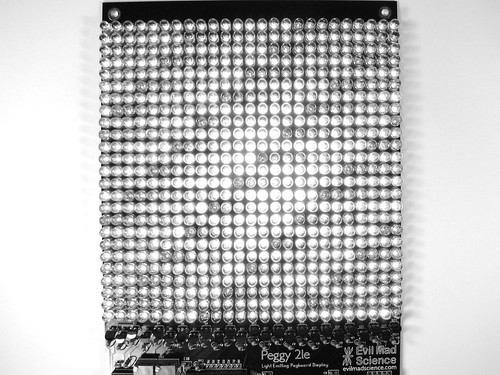
The Peggy 2 and 2LE are multiplexed LED matrices, which means that they’re wired up as a matrix of 25 rows and 25 columns. The anodes of every LED in any given row are wired together. Similarly, the cathodes of every LED in any given column are wired together.
So, to wire up an external array of 25 rows × 25 columns, you only need to run 50 output wires to your external matrix: One wire from each row and column. An easy approach is to pick the anode (square pin) from every LED in the leftmost column and the cathode (round pin) from every LED in the bottommost row, and that lets you drive up to 625 LEDs.
Now, Tony’s original question was actually about driving a 20 × 30 matrix with “30 anode connections and 20 cathodes”, or in other words, 30 rows and 20 columns. For subtle reasons that we’ll get to in a moment, it’s actually better to build a 30 × 20 matrix (that is, one with 30 columns and 20 rows): It’s easier to assemble, requires no additional hardware, and (perhaps surprisingly) 50% brighter than the other orientation.
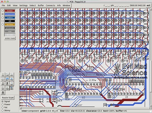
To drive additional rows (going from the normal 25 rows up to 30 rows), you can break out the additional outputs from U3, shown in the lower right of the image above. Each of those outputs can drive a high-side PNP transistor (through a resistor) that can switch on the current to additional row of LEDs.
The existing transistors are Q0-Q24 (which drive rows 0-24) so these new ones might be called Q25-Q29, and the corresponding resistors would be RB25-RB29. (It is also necessary to modify the software to scan through 30 rows, instead of 25.)

To drive additional columns (going from 25 to 30, or even 32 columns), you do not need to add any additional hardware. Just wire the additional columns to pins A0-A4 (or A0-A6) on U5. You will also have to modify the software to send the additional data to the additional columns, but that’s almost a trivial change, because we are already sending 32 bits of data to the column driver chips. Only, we normally just send zeroes to those unused columns. Assuming that you’re sticking to the 20 × 30 LED grid plan, you can also modify the software to only scan through 20 rows, instead of 25.
Now, here’s the kicker. The Peggy 2 (and 2LE) are multiplexed LED displays, which means that only one row is actually driven at any given instant. So, if you add additional columns instead of rows you’re now scanning through 20 rows instead of 30, which means that each row is on 1/20 of the time, rather than 1/30 of the time. Comparing the two, the effective overall “brightness” of the display built with this orientation then is (1/20)/(1/30) = 150% of the brightness if it were built with 20 columns and 30 rows.

I can’t help thinking that there are some veteran solderers who are now wishing they had this info’ a while ago!
One typo, I assume: “and the corresponding [resistors] would be RB25-RB29”?
Yup, and thanks!