


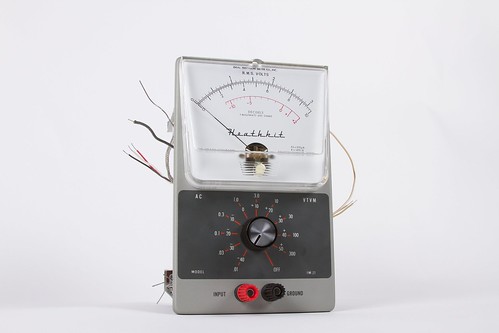
Last part we unboxed the Heathkit, looked at all the components, and started to build some of it. Now it’s time to finish off the build with the three main plates. This part is cool as you are able to see the creation come together before your eyes. We even created our own replacement part!
We also saw some cool vintage Heathkits at the Electronics Flea Market, and will show some pictures of those. Read on for more!
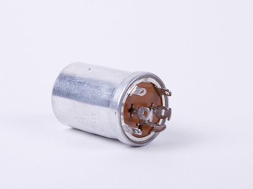
Our first adventure is with the big capacitor again. We hit a roadblock when the first mounting wafer didn’t fit the plate and the capacitor. We took some measurements and used Inventor to model it up to cut out on the laser cutter.
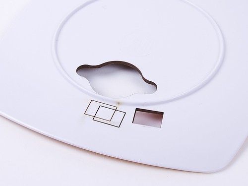
After two test cuts done with cardboard, it was time to cut it out of more sturdy material. For this material we used a melamine plate. The rectangles are some test cuts.
Here’s how it came out! (Surprise! It’s colourful!) The cuts were very precise. If you are also missing your capacitor plate, you can download ours from Thingiverse and cut it out!
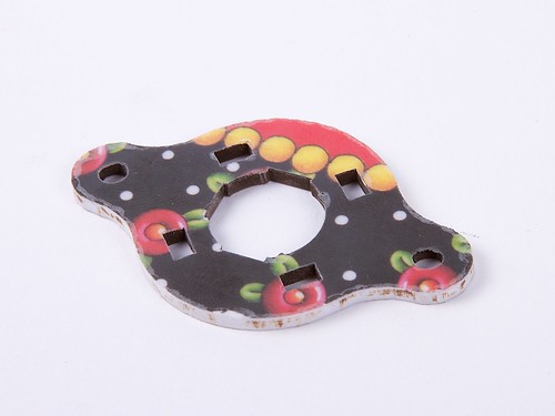
Most importantly, it fits!
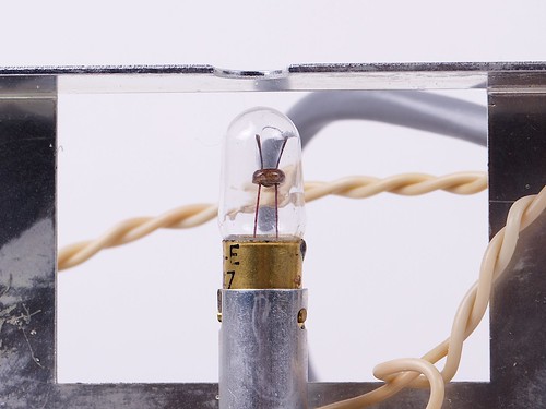
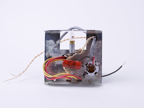
Here is an interesting component: it’s a tiny lightbulb! Used to backlight the meter probably. It is inserted by pushing down and twisting.
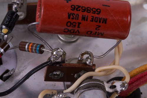
Here was everything that needed to get soldered. The soldering for this was a little different than soldering kits that work with Arduinos, as you need to use a lot of solder. The wires and leads are much bigger, as well as the tabs, so the contacts have to have a lot of solder.
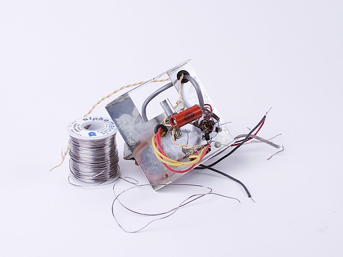
Here’s a closeup as the solder blobs. As mentioned before, the components are really big!
After it was all soldered together it started to look a little bit more tidy. There is lots of room inside now thanks to the excess of leads being trimmed off. The solder from one of the capacitor lugs to the metal casing needs to be improved- it’s only a temporary measure.
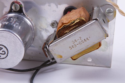
The transformer seems pretty interesting. This is its number…
After working on the top plate, it was time to work on the bottom plate. The bottom plate was much busier than the top plate!
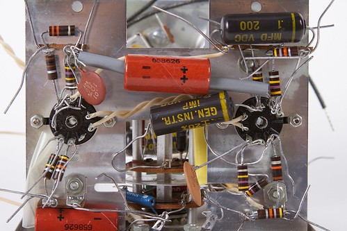
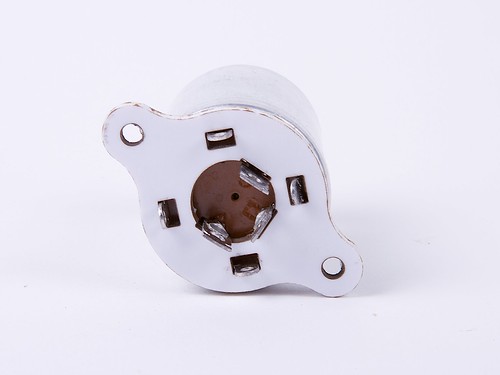
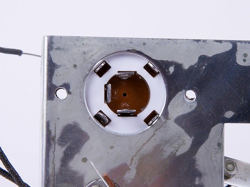
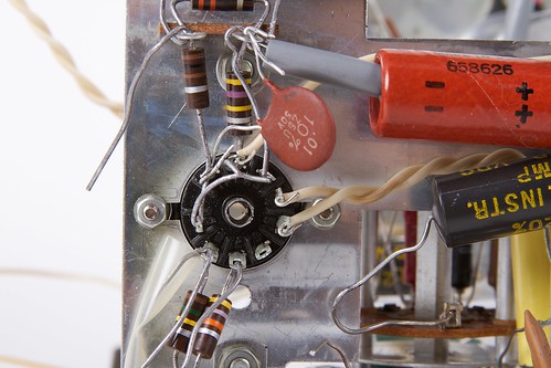
This is the plate that hosts the two tube sockets on it, which is pretty cool! There are connections going from the two sockets to everywhere.
Tube socket 1:
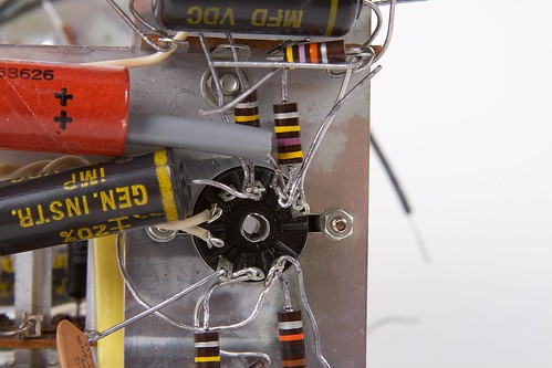
Tube socket 2:
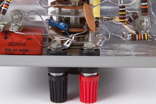
There is also the black and red lugs on this plate, which is quite exciting! Eventually our test probes will connect into these.
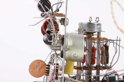
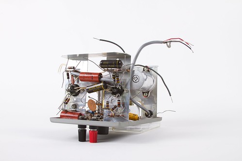
From the side view you can really see how many components are on this plate. Wow!
This plate gets mounted on the other plates. We’re starting to form a box!
This was great progress so far. Next time, this will all be soldered, there will be a few more components added, and we’l be adding a few more sides to it!
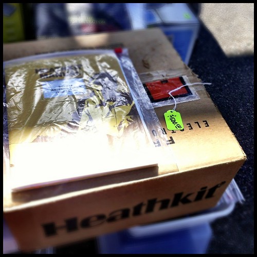
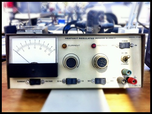
Switching gears now! At the Electronics Flea Market there were quite a few Heathkits around! As you can see here, Heathkits are taken seriously in their mint-preserving measures, and are quite valuable.
There were very many built Heathkits around!
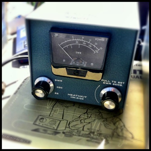
If you’re a true collector, there were some good deals (ok, more like “so-so” deals) around!
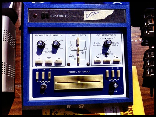
It was really cool to see the really vintage ones, like this signal generator with its knobs and wheel!
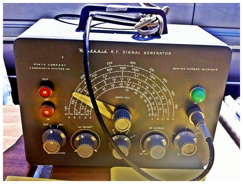
One of the things that is striking about Heathkits was their design. This one demonstrates it quite adequately. The appearance is very plain yet clear, so you can focus on the controls rather than the text. This one just looks like it is begging to be in use!
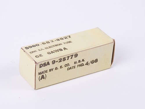
Also at the flea market we were able to find one replacement tube, just in case it is broken! Plus, extra tubes are pretty cool!
Up next there will be some soldering, some more building, and pretty soon it will start looking like a real put-together project! Maybe it will be functional, or perhaps it will be a static art project with some added LEDs!
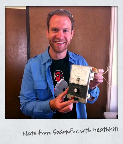
After Maker Faire, Nate from Sparkfun visited and totally wanted a picture with the Heathkit! Check it out!
The stories that everyone left on last post about their Heathkits were very cool. One of the interesting commonalities was that people built Heathkits because they needed to use the finished device, as they couldn’t get one otherwise. Maybe something to keep in mind now with more modern kits!
More build photos can be found on flickr here:
Feel free to share your Heathkit stories or your best find at the electronic flea market in the comments below, or on Google+ / Twitter! Keep on vintage making, everyone!

Nice work on the build! I bought a few already-assembled Heathkits, the IO-12 (did I call it an IO-10 last time?), and… of all things, two of the ones you posted pictures of, the RF generator and the audio generator. Tubes are cool. One of these days (when the AVC is over…) I may see about building some tube audio gear… anyway enjoyed reading the Artist-in-Residence posts! -Michael
RobotGrrl, you inspire so many memories with your wonderful documentation. I built many Heathkits back in the day (oscilloscope, VTVM, signal generator, DX-20 ham transmitter, others …). This was in the 1950s (I heard the first Sputnik in 1957 on my short wave receiver!). I was always building stuff, mostly with tubes, but when the CK722 transistor came out I started making solid state goodies too.
My junior high teachers liked it when I would bring my projects to school (along with Heathkit test equipment as needed) and do live show ‘n tell in front of class. I have tons of old-timer stories! I still love DIY & making, except these days it’s Arduino!
Thanks EMS folks for extending hospitality to RG during her US visit. :D
You’ve started ruining your pictures with hipstagram too :(
Spare Tubes – always good to snag some, however in several years now of restoring old radios & test gear, the tubes are almost always good. It’s always the electrolytic and film capacitors that go bad.
A tip on the Dial Lamp – if the little red film that they provide to stick over the hole (makes the lamp look RED from the front) is missing or the adhesive has gone bad (from so many years in the box), you can buy plain-old automotive tail-light repair tape, from Walmart for about $2. I’ve used this on a number of test gear items that HAD red filter (but it flaked off). It looks right and appears to take the heat.
Mike Yancey
KM5Z
Dallas, Texas
It looks like the big capacitor would have fitted without the mounting plate: you could have just mounted it on the frame and bent the outside contacts out to keep it from moving around. I wonder if that’s why there wasn’t any matching mounting plate in the package…
Just so you know (though you may already), that “Push down and twist” bulb is called a “Bayonet” mount. They’re what all household light bulbs are like in the UK and IIRC, Europe (albeit bigger), where the “Edison Screw” mount is more rare.