


This past week we introduced our “Three Fives” discrete 555 timer kit, which comes with a set of “legs” to make it look like a (DIP packaged) integrated circuit. In that introduction, we mentioned that the legs are machined and formed from PVC foam. But what exactly does that mean? Here (in gory step by step detail) is how we make them!
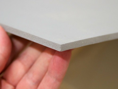
Our material of choice is expanded PVC foam, which is an extremely tough, lightweight, and semi-rigid material that is a lot like an impact-resistant plastic version of balsa wood. It is sold under trade names including Celtec, Komatex, and Sintra. The version that we’re using is about 1/4″ thick, and is light gray in color.
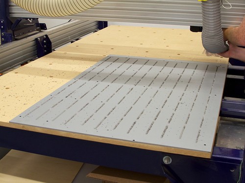
In the first part of the process, we mount the sheets and machine them on a CNC router.
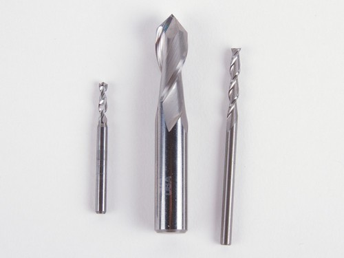
We use three different cutting tools in the CNC router, in sequence: A specialty drill bit, a 90° drill-point endmill, and a regular 2-flute 1/8″ diameter endmill.
(Tech specs, for those interested: The drill is #38; 0.1015″ diameter, and the 90° tool is 3/8″ in diameter. All three tools are uncoated solid carbide.)
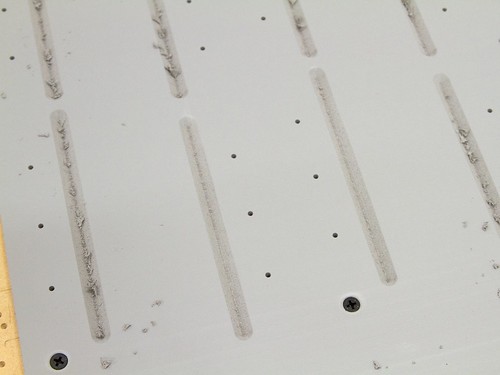
We begin by screwing the pvc foam down to the bed of the CNC router to keep the material flat while machining. After that, we use the drill bit to make an array of precisely-cut pilot holes, and then the 90° drill-point endmill to make a set of vee-grooves that cut 3/4 of the way through the material.
Those precisely-cut pilot holes are for the 6-32 machine screws that will attach the legs to the circuit board in the kit.
Aside: It’s a little bit unusual to use machine screws in this type of application, where wood screws or thread-forming screws would normally be used. However, with a carefully chosen (and well-controlled) pilot hole size, machine screws turn out to form excellent threads in pvc foam, without leaving pointy ends exposed to fingers.
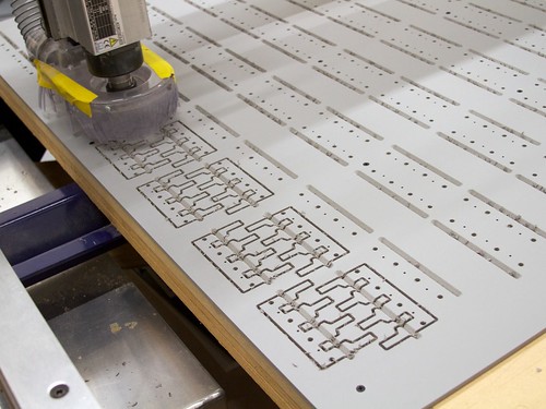
Finally, we begin cutting with the 1/8″ diameter endmill, for which there are actually two separate operations. The first is routing an array of larger-diameter holes, which will constitute clearance holes for the 555 kit’s terminal posts, and the second is to cut out the individual shapes.
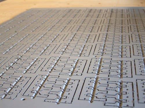
We don’t actually cut the parts completely out of the sheet, but rather leave them “tabbed in” with a few little carefully-placed bridges that aren’t fully cut through. These tabs ensure that the parts stay put while their outlines are cut. After we’re done cutting the full sheet, we use a hand chisel or small saw to cut the individual parts free.
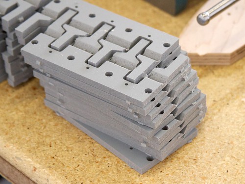
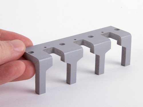
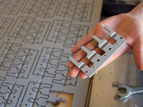
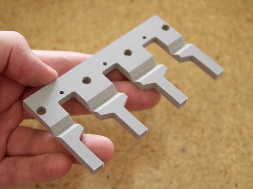
And so we end up with giant stacks of the leg “preforms,” precisely cut, but with the tabs still present.
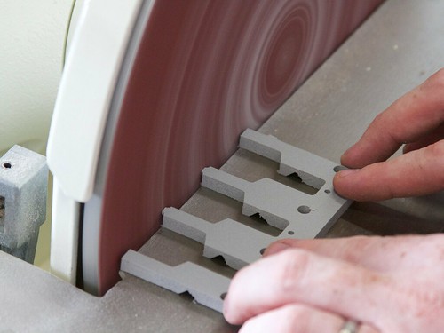
We sand away the tabs on all four sides with a 12″ disc sander.
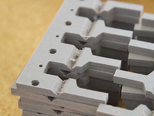
The sander also removes the vast majority of the burrs on the edges of the preforms, but does not remove any of the burrs or debris left inside the 90° vee-groove cut by the drill-point endmill.
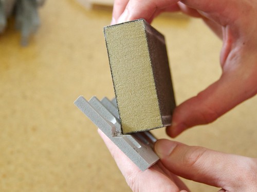
Since the vee-groove is a clean 90°, we can use a square-profile file or a sanding sponge (shown here) to clean it out.
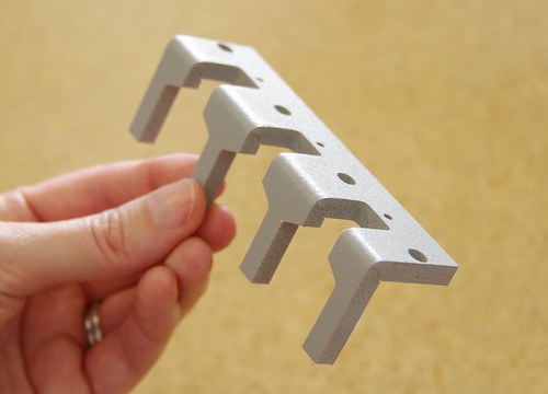
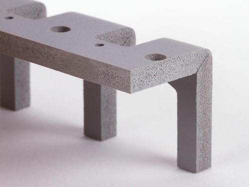
And here is the completed preform, ready to bend.
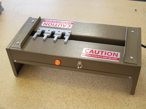
This is a Quincy Lab Model #03-160 plastic-bending strip heater, which we use to soften and bend the legs. It takes about 20-30 seconds to soften the plastic enough (at its thinnest point) to bend easily, during which we flip it twice to ensure even warming.
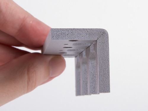
Once the plastic is soft enough to bend, the legs fold easily to shape against a straightedge, in a 90° “miter fold,” and we hold it in place while the plastic cools, another 10-20 seconds.
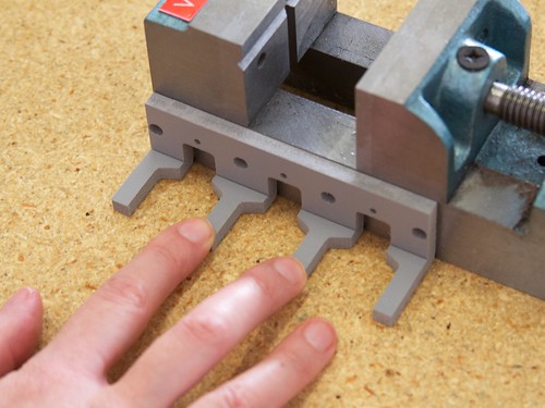
After folding, we check to make sure that each bend is nicely square. (A proper angle plate is on the way; in the meantime, we’re using the side of this precision-ground drill press vise as a reference.)
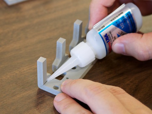
The last step is a drop of glue to strengthen the fold, which would otherwise be a weak point in the structure. As we learned from Solarbotics, thin CA glue works incredibly well to join PVC foam.
In the planning stages, before we had actually fabricated any legs to try out, we weren’t sure how strong the material would be in practice— after all, it is a type of foam, a little bit flexible, and we’re using it in thin cross-sections. And so our original plan had been to regard the legs as non-structural parts, and to use a set of aluminum standoffs (hidden beneath the legs) to actually hold up the circuit board. However, after forming our first sets of legs (and especially, after adding the glue), the legs turned out to remarkably strong on their own, and the idea of adding additional supports seemed simply absurd.
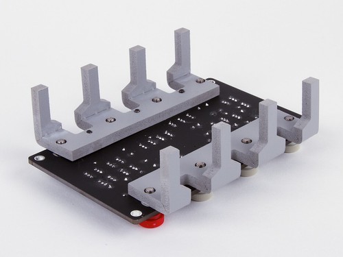
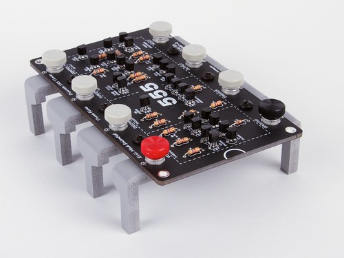
And finally, here are how the legs look mounted to our happy little (great big) 555 timer. On the bottom side, you can see the three little black screws that hold the legs in place, and that the larger-size clearance holes allow the terminal posts (thumbscrews) to pass unimpeded.
The “Three Fives” Discrete 555 Timer kit is available now at the Evil Mad Scientist shop.

Looks like a great material – never tried it but I must do sometime.
Since the legs are removable, does that mean the three fives will be available in an alternative “SOIC” package?
Hmmmmm…. not a bad idea!
That Sir, is teh awesomez…
Huzzah!
How about a LM3909N version that would be awesome.