


Home › Evil Mad Scientist Forums › LED Matrix Kits › help needed to in getting Meggy RGB Jr. going (newbies)
- This topic has 5 replies, 2 voices, and was last updated 14 years ago by Windell Oskay.
-
AuthorPosts
-
June 10, 2012 at 3:42 pm #20062pmorjeParticipant
Hi,
We (my son, age 10 and I ) have finished soldering our Meggy RGB Jr and and trying to get the default game (“Attack of cherry tomatoes”) woking. Its possible we have bad connections but I have looked many times and do not want to get into re-soldering and damaging. This is the status on startup:
The 8×8 display seems to startup correctly, but the yellow diodes, D0, D2, D3, D4 light-up. My son tells me that correct behaviour is D0, D1, D2, D3 should light-up. If we start playing anyway, circular button labelled b1 or “A” has no effect. Other circular button (b0 or “B”) shoots as expected and the four square buttons on left also work as expected. After a few seconds the game ends (because “A” cannot used to play) and yellow diodes start a running display. All diodes light up except D1.
The connections below diode D1 and button “A” look ok.
We have a multi-meter but don’t know what to look for to debug these issues.
Thanks for your help.
June 10, 2012 at 5:07 pm #20714Windell OskayKeymasterThe correct behavior on startup is that D0, D1, D2, D3, and D4 should light up. So, it’s not that some of your LEDs are shifted, it’s just that one of them is not lighting up. Check the soldering at that LED location, and at the pins of the LED driver chips. Also make sure that that D1 is installed with the correct orientation.
Check the soldering at button “A” (aka location b1 on the circuit board) and the corresponding pin of the microcontroller, which is the pin located directly above the hole labeled PC1.You may also want to download the Meggy Jr RGB schematic, to help figure out where to put the multimeter, if you want to do this that way: https://wiki.evilmadscientist.com/Meggy_Jr_RGBJune 12, 2012 at 9:45 am #20715pmorjeParticipantThanks for your help.
The LED D1 issue is resolvable because I tried spare LED that came with the kit with temporary connections and it worked fine. When I solder the good LED onto the board, this issue will get resolved.
Regarding. button b1, I don’t yet know what is going on. With power on, the voltage at hole PC1 is about 4.3V but voltage any of four connections at b1 (button not pressed) is 0. Is b1 getting somehow grounded or connection fron PC1 to b1 is bad ? (BTW, I cannot see this connection on the back of the PCB, front connections are now hiding under components)
Comparing this to button b0 (which works), the voltage is 4.3V at two of its connections when not pressed and goes to 0 when pressed. That sounds like correct behaviour.
I have checked solders on the back of b1, they look ok (not too much or too little solder)
What can I do to resolve issue with button b1 ?
Thanks.
June 12, 2012 at 1:40 pm #20716Windell OskayKeymasterIf you managed to damage the first LED D1 when you soldered it in, you may want to be a little more gentle with your soldering– those don’t usually fail.
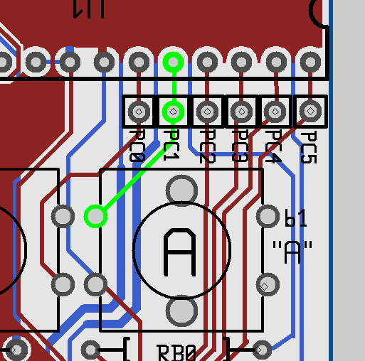 The connection of button b1 to pin PC1 is shown above. If you’re reading 0 V on that pin, then it is likely that there’s a bad connection between the two points. Check to see if there is actually a connection between these two points. (You can do that from the top or bottom of the board.)
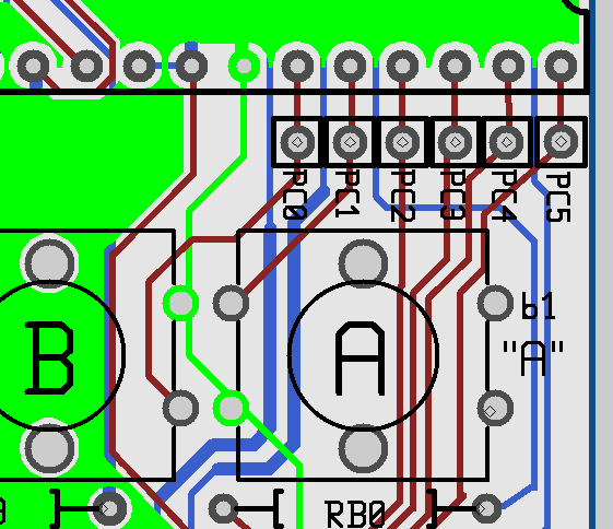 One pin of button b1 is connected to ground. Check to see if it is actually connected, say to the pin to the left of PC0.Then, check to see if this pin is electrically connected to the PC0 when the button is and is not pressed.June 13, 2012 at 11:08 am #20717pmorjeParticipant
Thanks for your help. I think I am closer to making it work.
A pin of b1 is supposed to be grouned by a connection on the board to a ground pin of b0. This connection on the board is not working. The ground pin of b0 is actually grounded but the ground pin of b1 is not. When I connect these two pins by a temporary connection, switch b1 starts working as expected.
So I am going make this connection permanent by soldering a short wire above the back of this board between these two pins. Is that the right thing to do ?
Thanks.
June 13, 2012 at 1:19 pm #20718Windell OskayKeymasterYes, that sounds like what I’d do. :)
-
AuthorPosts
- You must be logged in to reply to this topic.