


An ever-present challenge in electronic circuit design is selecting suitable components that not only perform their intended task but also will survive under foreseeable operating conditions. A big part of that process is making sure that your components will stay within their safe operating limits in terms of current, voltage, and power. Of those three, the “power” portion is often the most difficult (for both newcomers and experts) because the safe operating area can depend so strongly on the particulars of the situation.
In what follows, we’ll introduce some of the basic concepts of power dissipation in electronic components, with an eye towards understanding how to select components for simple circuits with power limitations in mind.
— STARTING SIMPLE —
Let’s begin with one of the simplest circuits imaginable: A battery hooked up to a single resistor:
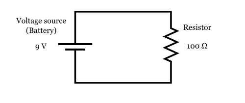
Here, we have a single 9 V battery, and a single 100 ? (100 Ohm) resistor, hooked up with wires to form a complete circuit.
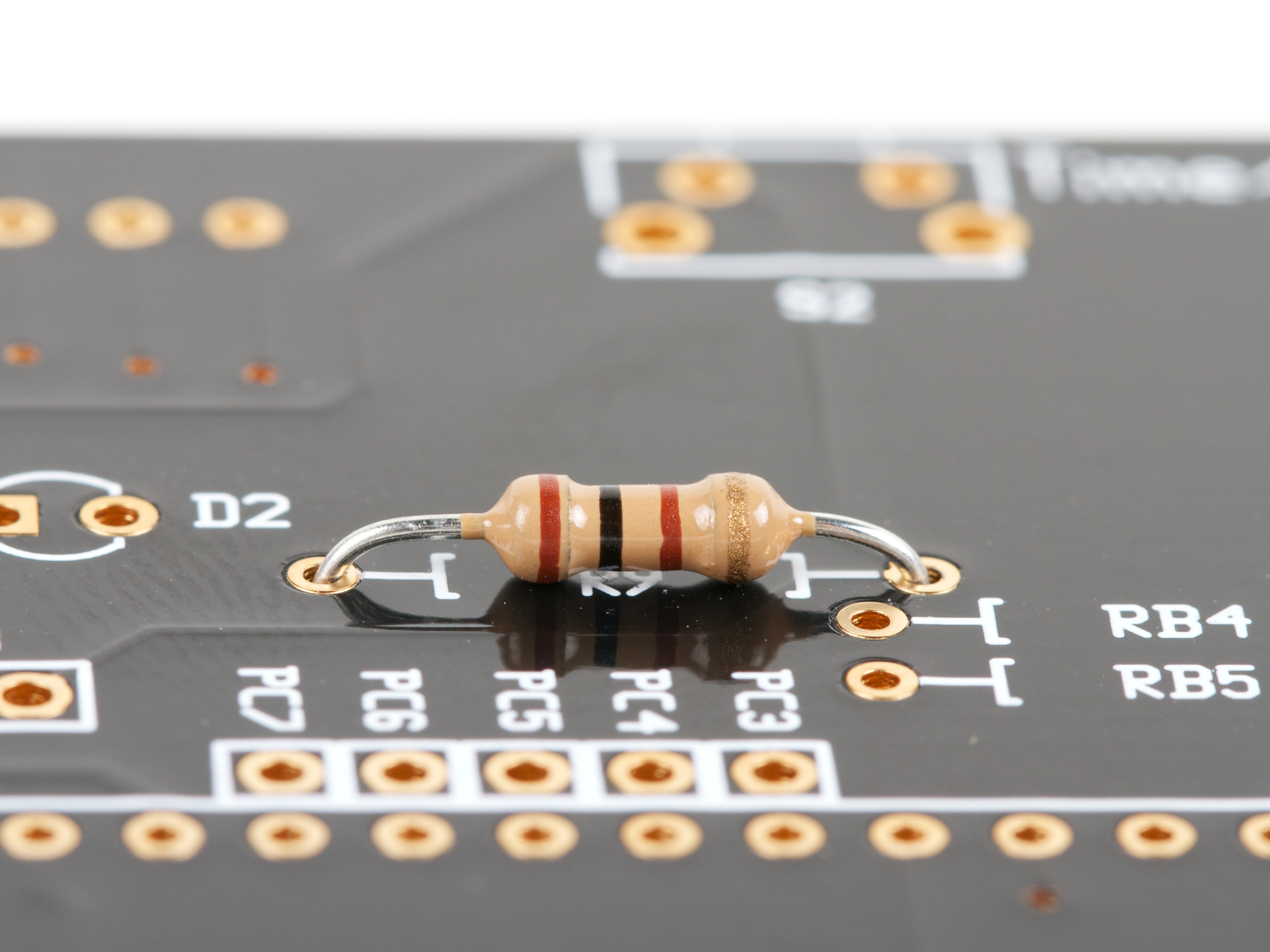
Easy enough, right? But now a question: If you want to actually build this circuit, how “big” of a 100 ? resistor do you need to use to make sure that it doesn’t overheat? That is to say, can we just use a “regular” ¼ W resistor, like the one shown below, or do we need to go bigger?
To find out, we need to be able to calculate the amount of power that the resistor will dissipate.
Here’s the general rule for calculating power dissipation:
Power Rule: P = I × V
If a current I flows through through a given element in your circuit, losing voltage V in the process, then the power dissipated by that circuit element is the product of that current and voltage: P = I × V.
Aside:
How can current times voltage end up giving us a “power” measurement?
To understand this, we need to remember what current and voltage physically represent.
Electric current is the rate of flow of electric charge through the circuit, normally expressed in amperes, where 1 ampere = 1 coulomb per second. (The coulomb is the SI unit of electric charge.)
Voltage, or more formally, electric potential, is the potential energy per unit of electric charge —across the circuit element in question. In most cases, you can think of this as the the amount of energy that is “used up” in the element, per unit of charge that passes through. Electric potential is normally measured in volts, where 1 volt = 1 joule per coulomb. (The joule is the SI unit of energy.)
So, if we take a current times a voltage, that gives us the amount of energy that is “used up” in the element, per unit of charge, times the number of those units of charge passing through the element per second:
1 ampere × 1 volt =
1 ( coulomb / second ) × 1 ( joule / coulomb ) =
1 joule / second
The resulting quantity is in units of one joule per second: a rate of flow of energy, better known as power. The SI unit of power is the watt, where 1 watt = 1 joule per second.
Finally then, we have
1 ampere × 1 volt = 1 watt
Back to our circuit! To use the power rule (P = I × V), we need to know both the current through the resistor, and the voltage across the resistor.
First, we use Ohm’s law ( V = I × R ), to find the current through the resistor.
• The voltage across the resistor is V = 9 V.
• The resistance of the resistor is R = 100 ?.
Therefore, the current through the resistor is:
Then, we can use the power rule ( P = I × V ), to find the power dissipated by the resistor.
• The current through the resistor is I = 90 mA.
• The voltage across the resistor is V = 9 V.
Therefore, the power dissipated in the resistor is:
So can you go ahead and use that 1/4 W resistor?
No, because it would likely fail from overheating.
The 100 ? resistor in this circuit needs to be rated for at least 0.81 W. Generally, one picks the next larger available size, 1 W in this case.
A 1 W resistor typically comes in a much larger physical package, like the one shown here:
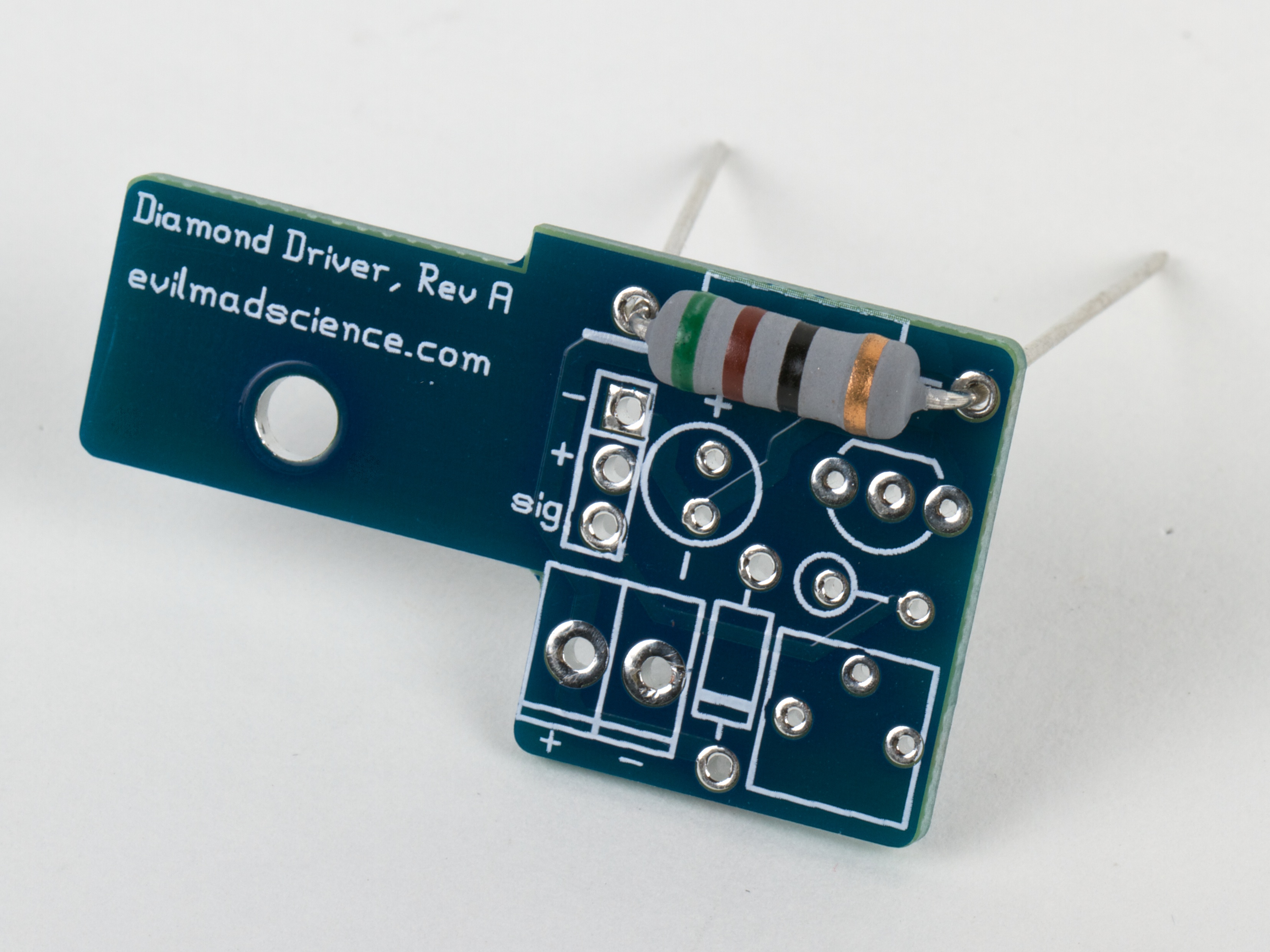
(A 1 W, 51 ? resistor, for size comparison.)
Because a 1 W resistor is much larger physically, it should be able to handle dissipating a higher amount of power, with its higher surface area and wider leads. (It may still get very hot to the touch, but it should not get hot enough that it fails.)
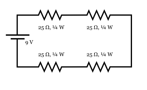
Here’s an alternate arrangement that works with four 25 ? resistors in series (which still adds up to 100 ?). In this case, the current through each resistor is still 90 mA. But, as there is only one quarter as much voltage across each resistor, there is only one quarter as much power dissipated in each resistor. For this arrangement, one only needs the four resistors to be rated for 1/4 W.
Aside: Working through that example.
Because the four resistors are in series, we can add their values together to get their total resistance, 100 ?. Using Ohm’s law with that total resistance gives us the 90 mA current again. And again, since the resistors are in series, the same current (90 mA) must flow through each, back to the battery. The voltage across each 25 ? resistor is then V = I × R, or 90 mA × 25 ? = 2.25 V. (To double check that this is reasonable, note that the voltages across the four resistors sum up to 4 × 2.25 V = 9 V.)
The power across each individual 25 ? resistor is P = I × V = 90 mA × 2.25 V ? 0.20 W, a safe level for use with a 1/4 W resistor. Intuitively, it also makes sense that if you divide up a 100 ? resistor into four equal parts, each should dissipate one quarter of the total power.
— ON BEYOND RESISTORS —
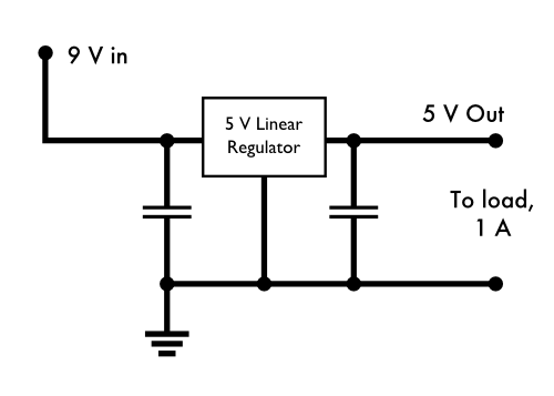
For our next example, let’s consider the following situation: Suppose that you have a circuit that takes input from a 9 V power supply, and has an onboard linear regulator to step the voltage down to 5 V, where everything actually runs. Your load, on the 5 V end, could be as high as 1 A.
What does the power look like in this situation?
The regulator essentially acts like a big variable resistor, that adjusts its resistance as needed to maintain a consistent 5 V output. When the output load is a full 1 A, the output power delivered by the regulator is 5 V × 1 A = 5 W, and the power input to the circuit by the 9 V power supply is 9 W. The voltage dropped across the regulator is 4 V, and at 1 A, that means that 4 W is dissipated by the linear regulator— also the difference between the power input and the power output.
In each part of this circuit, the power relationship is given by P = I × V. Two parts — the regulator and the load — are places where power is dissipated. And in the part of the circuit across the power supply, P = I × V describes the power input to the system— the voltage increases as the current travels across the power supply.
Additionally, it is worth noting that we have not said what kind of load is pulling that 1 A. Power is being consumed, but that does not necessarily mean that it is being converted into (just) heat energy— it could be powering a motor, or powering a set of battery chargers for example.
Aside:
While a linear voltage regulator setup like this is a very common setup for electronics, it’s worth pointing out that this is also an incredibly inefficient arrangement: 4/9 of the input power is simply burned off as heat, even when operated at lower currents.
— WHEN THERE ISN’T A SIMPLE “POWER” SPECIFICATION —
Next, a slightly more challenging part: making sure that your regulator can handle the power. While resistors are clearly labeled with their power capacity, linear regulators are not always. In our regulator example above, let’s further suppose that we’re using a L7805ABV regulator from ST (datasheet here).
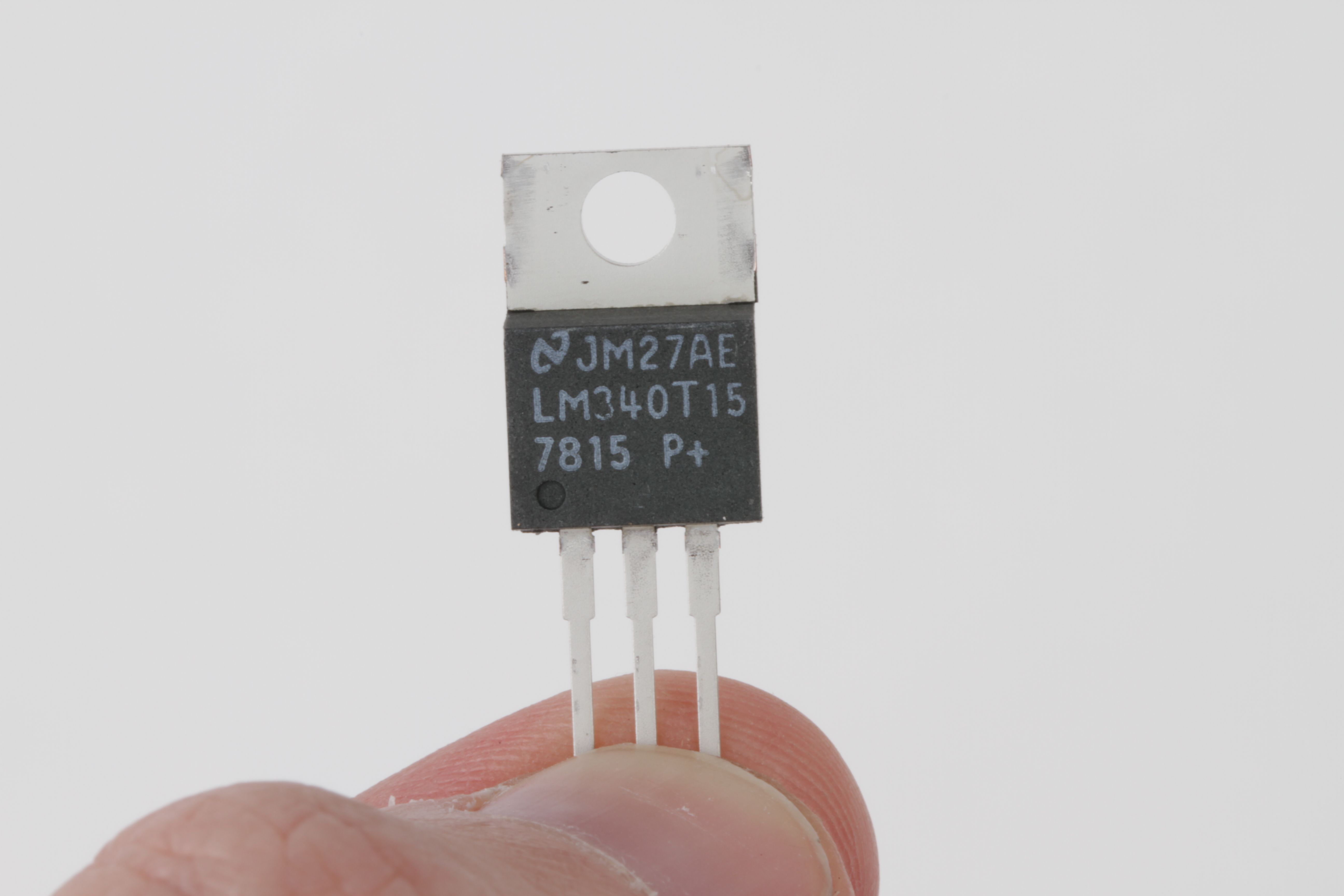
(Photo: A typical TO-220 case, the type typically used for medium-power linear regulators)
The L7805ABV is a 5 V linear regulator in a TO-220 package (similar to the one shown above), that is rated for 1.5 A output current and up to 35 V input voltage.
Naively, you might guess that you can hook this right up to 35 V input, and expect to get 1.5 A of output, meaning that the regulator would be radiating 30 V * 1.5 A = 45 W of power. But this is a tiny plastic package; it actually can’t handle that much power. If you look in the datasheet under the “Absolute maximum ratings” section, to try and find how much power it can handle, all that it says is “Internally limited” — which is anything but clear on its own.
It does turn out that there is an actual power rating, but it’s usually somewhat “hidden” within the datasheet. You can figure it out by looking at a couple of related specifications:
• TOP, Operating junction temperature range: -40 to 125 °C
• RthJA, Thermal resistance junction-ambient: 50 °C/W
• RthJC, Thermal resistance junction-case: 5 °C/W
The Operating junction temperature range, TOP, specifies how hot the “junction”– the active part of the regulator integrated circuit –can be allowed to get before it goes into thermal shutdown. (The thermal shutdown is the internal limit that makes the regulator power “Internally limited”.) For us, that’s a maximum of 125 °C.
The thermal resistance junction-ambient RthJA (Often written as ?JA), tells us how hot the junction gets when (1) the regulator is dissipating a given amount of power and (2) the regulator is sitting in open air, at a given ambient temperature. Suppose that we need to design our regulator to only work under modest commercial conditions, that will not exceed 60 °C. If we need to keep the junction temperature under 125 °C, then the maximum temperature rise that we can allow is 65°C. If we have RthJA of 50 °C/W, then the maximum power dissipation that we can allow is 65/50 = 1.3 W, if we are to prevent the regulator from going into thermal shutdown. That’s well below the 4 W that we would expect with a 1 A load current. In fact, we can only tolerate 1.3 W / 4 V = 325 mA of average output current without sending the regulator into thermal shutdown.
This, however, is for the case of the TO-220 radiating to ambient air– almost a worst-case situation. If we can add a heat sink or otherwise cool the regulator, we can do much better.
The opposite end of the spectrum is given by the other thermal specification: the thermal resistance junction-case, RthJC. This specifies how much temperature difference you can expect between the junction and the outside of the TO-220 package: only 5 °C/W. This is the relevant number if you can quickly remove heat from the package, for example if you have a very good heat sink hooked up to the outside of the TO-220 package. With a big heat sink and perfect coupling to that heat sink, at 4 W, the junction temperature would rise only 20 °C above the temperature of your heat sink. This represents the absolute minimum heating that you can expect under ideal conditions.
Depending on the engineering requirements, you can start from this point to build a full power budget, to account for the thermal conductivity of every element of your system, from the regulator itself, to the thermal interface pad between it and the heat sink, to the thermal coupling of the heat sink to the ambient air. You can then verify the couplings and relative temperatures of each component with a spot-reading non-contact infrared thermometer. But often, it’s a better choice to re-evaluate the situation and see if there’s a better way to go about this.
For the present situation, one might consider moving to a surface mount regulator that offers better power handling capability (by using the circuit board as a heat sink) or it may be worth looking into adding a power resistor (or zener diode) before the regulator to drop most of the voltage outside the regulator package, easing the load on it. Or better yet, seeing if there’s a way to build your circuit without the lossy linear regulator stage.
— AFTERWORD —
We have covered the basics of understanding power dissipation in a few simple, dc circuits.
The principles that we have gone over are quite general, and can be used to help understand power consumption in most types of passive elements and even most types of integrated circuits. There are real limitations, however, and one could spend a lifetime learning the nuances of power consumption, particularly at lower currents or high frequencies where small losses that we have neglected become important.
In ac circuits, many things behave very differently, but the power rule still holds in most circumstances: P(t) = I(t) × V(t) for time-varying current and voltage. And, not all regulators are all that lossy: Switching power supplies can convert (for example) 9 V dc to 5 V dc with 90% or higher efficiency– meaning that with good design, it may only take about 0.6 A at 9 V to produce 5 V at 1 A. But that’s a story for another time.
Good article, but… (1) its hard to compare sizes of the resistor when the photos have different resolutions (2) any guidelines on how much we can trim the leads, as they are important for power dissipation?
If I use a resistor of more than 1/2W, I always make sure to leave a gap between the bottom of the resistor and the PC board. As well, I am careful not to put temperature sensitive components right by it. The resistor can take the heat, but you can be sure the PC board will cook eventually, and diodes will leak (electrically) and transistor biases will drift, etc… Under the PC board, I trim the leads like any other components.
My Grandfather thinks those looks like candy.
Dropping from 9V (say a PP3 battery) to 5V (for a microcontroller) is a pretty common situation and so a great example. 1A is probably more than you might typically need for that application but add in a couple of 1W LEDs and you could easily get there.
I would be very useful if you could indicate what sort of common heat-sink might typically sovle the over-power issue and allow a safe 4W heat dissipation. Obviously it would only be a guide but somewhere between bolting it to an old key and taking the heat-sink off a Pentium-4 there must be a "this ought to do it" level that can be judged from experience.
Interested to know what you would pick if faced with this situation and a box of mixed heat-sinks.
Heat sinks (sold for that purpose) have ratings. If you know the power dissipation, you can look up all the thermal resistances and calculate the temperature rise from ambient all the way back to the die. Basically, you take the various theta’s and add them together. You have theta from junction to case, theta from case to heatsink, and the heatsink has a theta to ambient. All those thetas times the power will give you the temperature rise above ambient. Then you figure your max ambient and you can calculate the junction temp. The math is all tractable, and you can rearrange to solve for whichever variable is of interest.
For improvised heatsinks, I think you would really have to have a lot of experience. But one thing that might help is to just imagine an incandescent lightbulb. A 25 watt bulb is too hot to touch. But if you ran a 25-Watt bulb at 4 Watts, it would probably just be warm. So if you need to dissipate 4 Watts, you probably need a heat sink with the area of a good old-fashioned light bulb or so. Hope that helps.
Another way to get rid of heat is to use a large copper pad on the PCB. If interested, read app notes on National’s website about heat dissipation with different types of pads for SOT223 transistors and regulators.
Some very small SMT devices have thermal pads on the bottom that have very low thermal resistance to the die. If you design the PCB right, you can pull an enormous amount of heat out of these tiny packages.
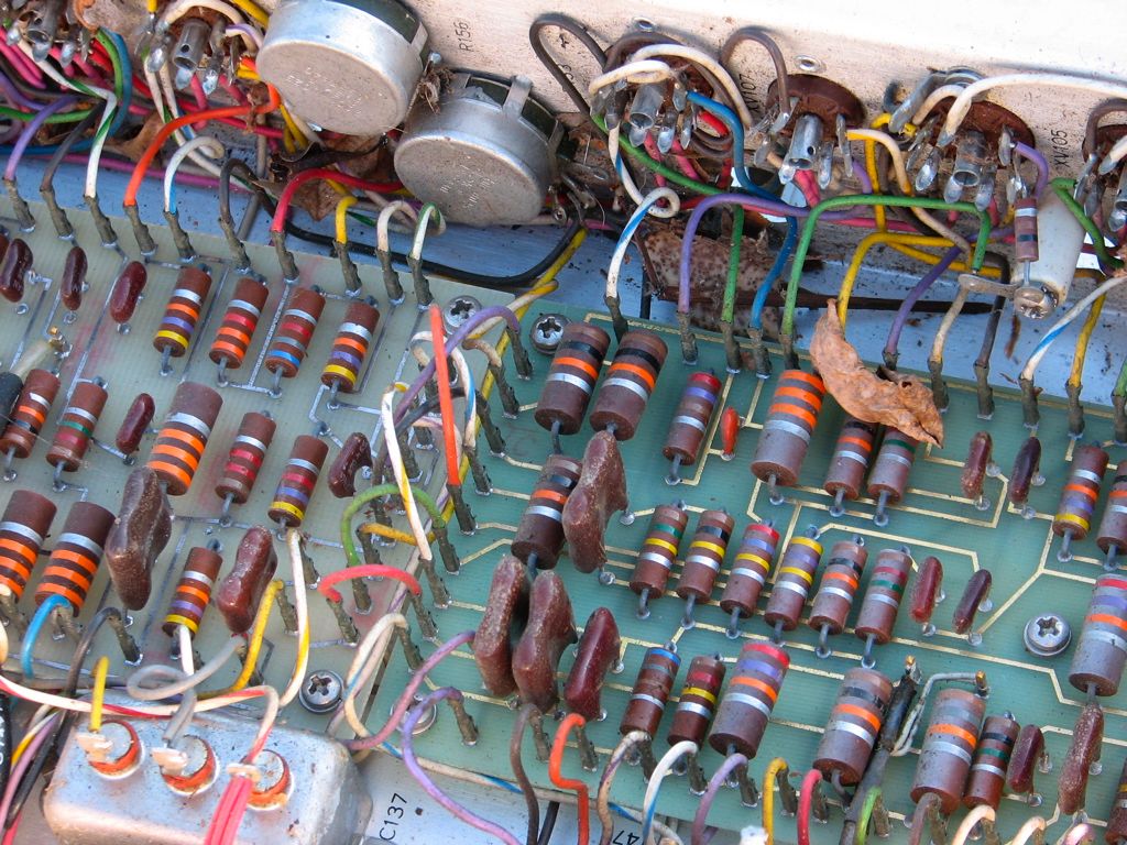
What’s the device in the last photo? Or better yet, maybe you should send it to Bunnie for one of his "Name That Ware" contests.
Click it and learn…
Great article! Thank you especially for the sidebar about why P = I * V.
One typo though: "to drop some most of the voltage"
Also, thank you for the Eggbot! It’s been well worth the money in terms of entertainment/learning/inspiration. :)
Why voltage in formulas are represented different in different countries.
I=U/R v.s. I=V/R?
There are a lot of different symbols used– not just by country but by academic discipline as well. There’s also (for example) J for current, E and U for electric potential, and so forth. Not everyone uses the same symbols, which is the reason that we are careful to explain what *our* symbols mean when we use them.
Windell H. Oskay
drwho(at)evilmadscientist.com
http://www.evilmadscientist.com/
Switching regulators are the way to go. They are really not that complicated and the efficiency just makes obsolete most of the discussion about power dissipation in those LM317’s and 7805/7812 linear regulators. I was powering a GPS in my car that needed 3v, and it only draws 240ma or so, this heated up an LM317 pretty hot, even with a heatsink, on 12v. I scrounged an old cell phone charger with a 34063a chip which is adjustable just like a LM317 and tuned it to 3v. This only draws about 60ma @ 12v on the input side, and makes no measurable heat, has no heatsink, in fact the ceramic package of the 34063a is about a quarter inch square, very tiny compared to the TO-220 package that the LM’s come in.
Linear regulators are still widely used and not likely to go away. One reason is that they can produce cleaner power. Another is that they are cheaper. In mass production, if power is not a big concern, nobody is going to fork out the extra money for an inductor and switching regulator when they could just use an LDO.
But when power is a concern, either because of heat dissipation or because the design will be battery operated, then switchers are often the better choice.
Thanks! Excellent post.
(often reader, never commentor)
The calculations for a resistor can be simplified.
We start with P = I × V
But in the case of a resistor, we can also write V = I × R
So we can deduce two new equations :
P = I × I × R = I² × R
P = V/R × V = V² / R
This makes the intermediary calculation of current of voltage unnecessary.
For example for a 9V battery, 100Ohm resitor : P = V² / R = 9² / 100 = 0.81W
Yes indeed! Good points, these!
Windell H. Oskay
drwho(at)evilmadscientist.com
http://www.evilmadscientist.com/
Resistance is a function of temperature; so if your resistor undergoes a significant temperature change (because it is dissipating a lot of power without adequate cooling) it will not have the resistance value you think it does.
Temperature coefficients can be important. But some resistors have very low temperature coefficients, meaning that the resistance does not vary much over temperature. If you care about the effect, then you should select those types. I think there is even an alloy (called invar?) that has a zero temperature coefficient.
Most good conductors become more resistive as they get hotter. Silicon has a positive temperature coefficient. It grows more conductive as it gets hotter.
Apparently, glass can also become somewhat conductive when heated enough. I’ve read you can melt glass into a puddle in a microwave oven if you just create a nice hot spot with a torch before you put it in the microwave. The hot glass is microwave absorbent (which means it is not a dielectric) and continues to absorb more and more heat until the whole thing melts. Never tried it.