Category Archives: Basics

Tips and Tales from the Workshop

I’ve been meaning to post a review of Tips and Tales from the Workshop by our friend Gareth Branwyn, but every time I start, I get distracted by the book itself. I keep flipping through and learning new things or being reminded of tricks I once knew.

The subtitle A Handy Reference for Makers is spot on. I imagine that if you’ve worked in a particular kind of workshop all of your life, you already know pretty much all the tricks for your field. What’s great about Gareth’s book is that he sought out tips from those life-long workshop inhabitants and shared them with dabblers like me who like to try all the things or who haven’t had the opportunity to spend the years it takes to amass that knowledge.

One of my favorite tips comes just after the forward in the “Tips credits” where Gareth lists people he gleaned these from.

All of these people are amazing makers and almost all of them have websites and YouTube channels. Do a search. Having all of these people on your radar will yield an ongoing and inspired feed of great shop tips, techniques, and project ideas.

I was tickled to see a bunch of friends names in the list (including our very own Windell) but also pleased to see new names to go seek out for inspiration.

As for the book itself, the illustrations are wonderful, and the organization into types of tasks totally makes sense. When a tool is mentioned, the discussion often delves into details of how the tool works and why it’s designed the way it is.

It is all good stuff, including the quality of the book. I love the way a freshly printed book smells, and the paper used for this is a pleasant weight with a smooth, almost glossy finish.

Thank you, Gareth! This book is a gem!

Basics: How Not to Solder

While there are a great many guides that teach you to solder (here is one fine example), we have found that there is a surprising lack of guides to help you with the opposite skill: How not to solder. This guide shows you some wonderful examples of how well circuits can come out when you disregard all of those other guides. Let’s get started!

Untitled

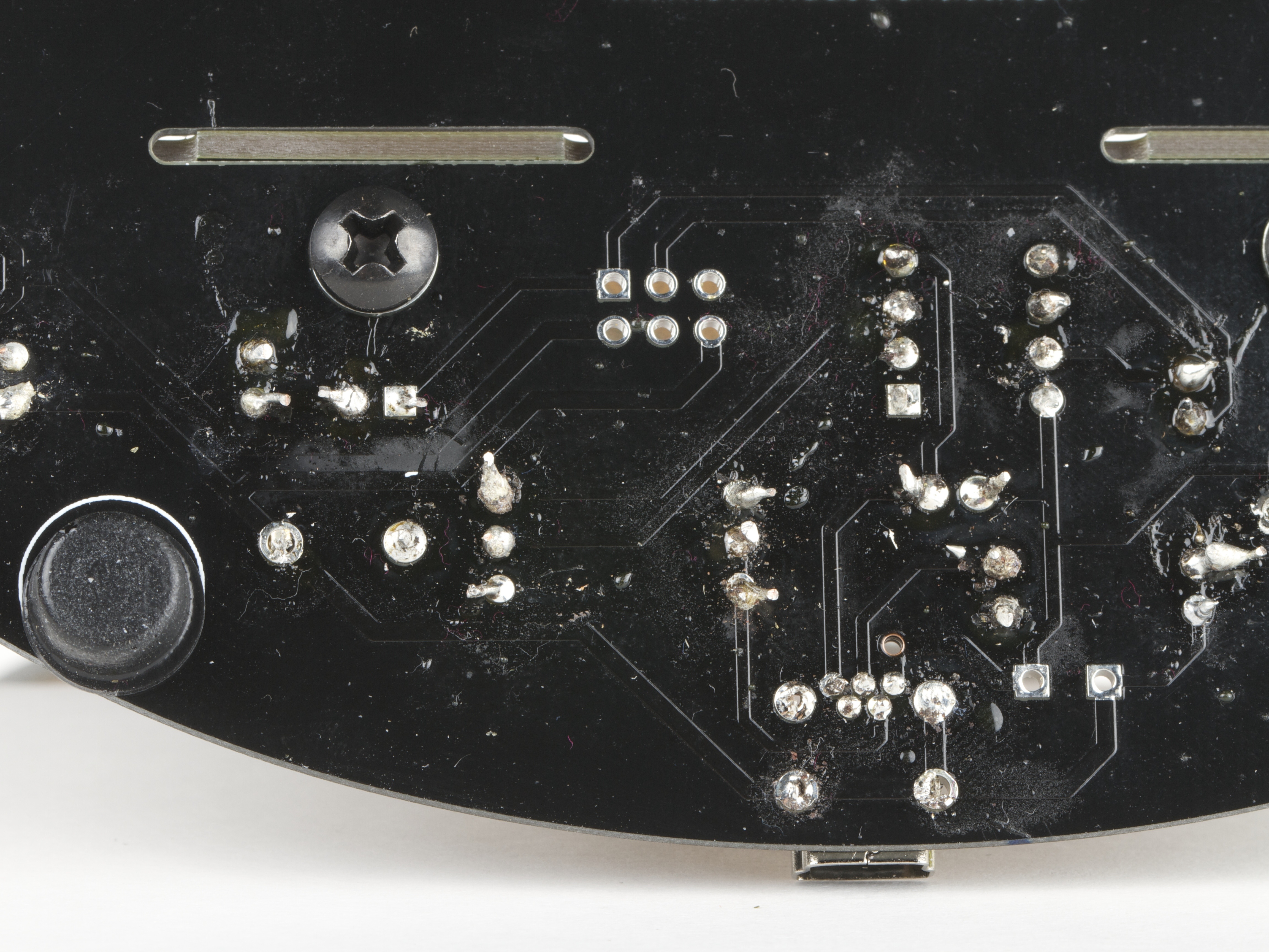
To begin with: Make sure that your circuit board is “generally messy.” A messy board might have leads trimmed to various lengths and/or extra little bits and blobs of solder and flux everywhere. Not only will the extra little bits of solder occasionally cause short circuits, but the disarray will help to hide other issues that might be lurking, making them nearly impossible to diagnose.

Untitled

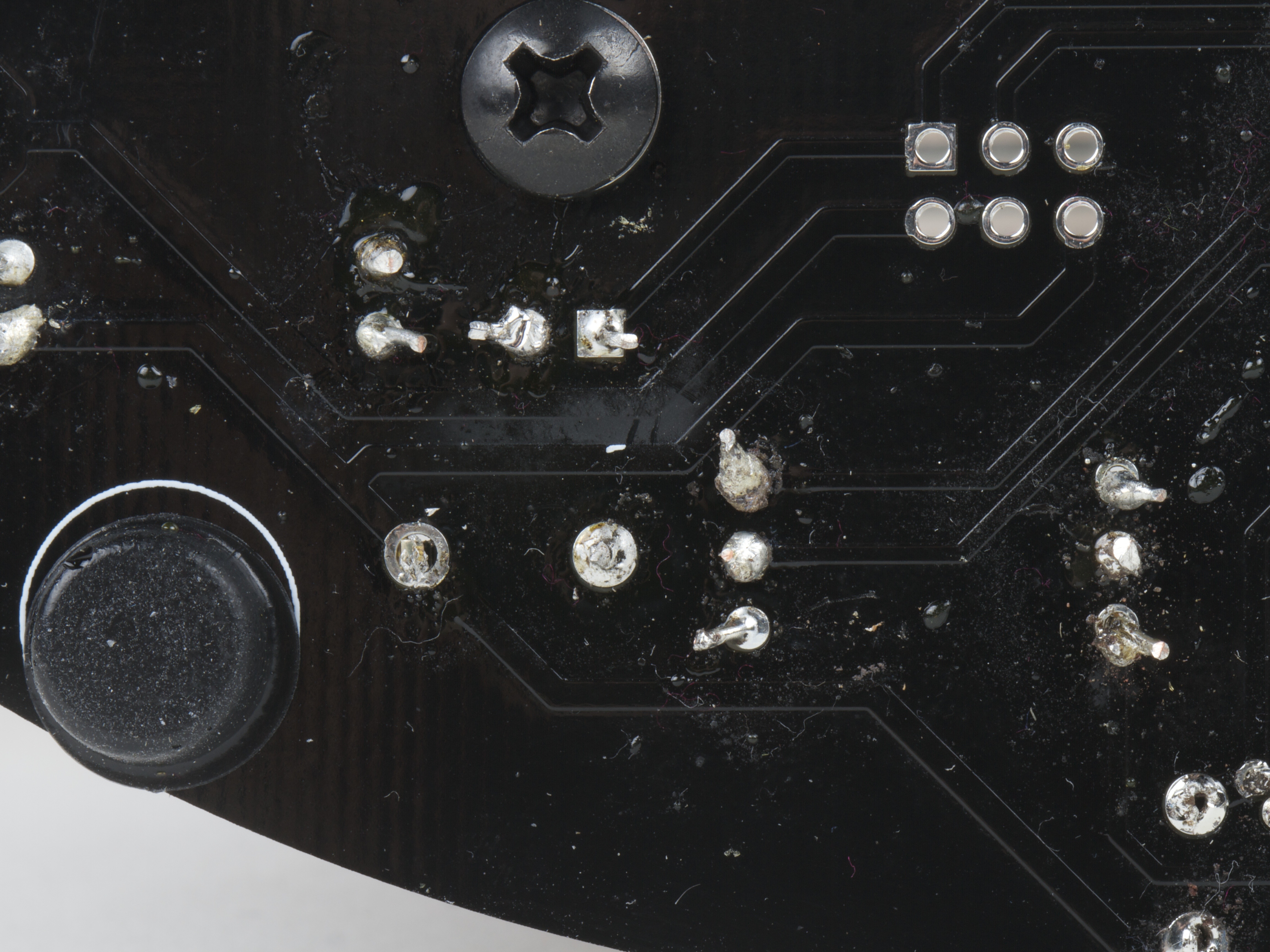
Zooming in on that same example, we can find incomplete solder joints like the one close to the rubber foot. A joint like this may look like it’s making an electrical connection, when in reality it may or may not be. These kinds of joints really are the best, because they can lead to intermittent connections that usually work. Intermittent connections are also a great way to prank anyone who likes to debug electronics. Think of it as making your own Annoy-a-tron!

Untitled

While most of the solder joints shown here have a clean, smooth meniscus, there are also two fine examples of connections that have gaps in the solder joint. Gaps like these are essential to ensure adequate ventilation of the electronic components on the other side. Some people may tell you that joints like these may crack (or break off entirely) over time, but don’t listen to them.

026 - Version 2

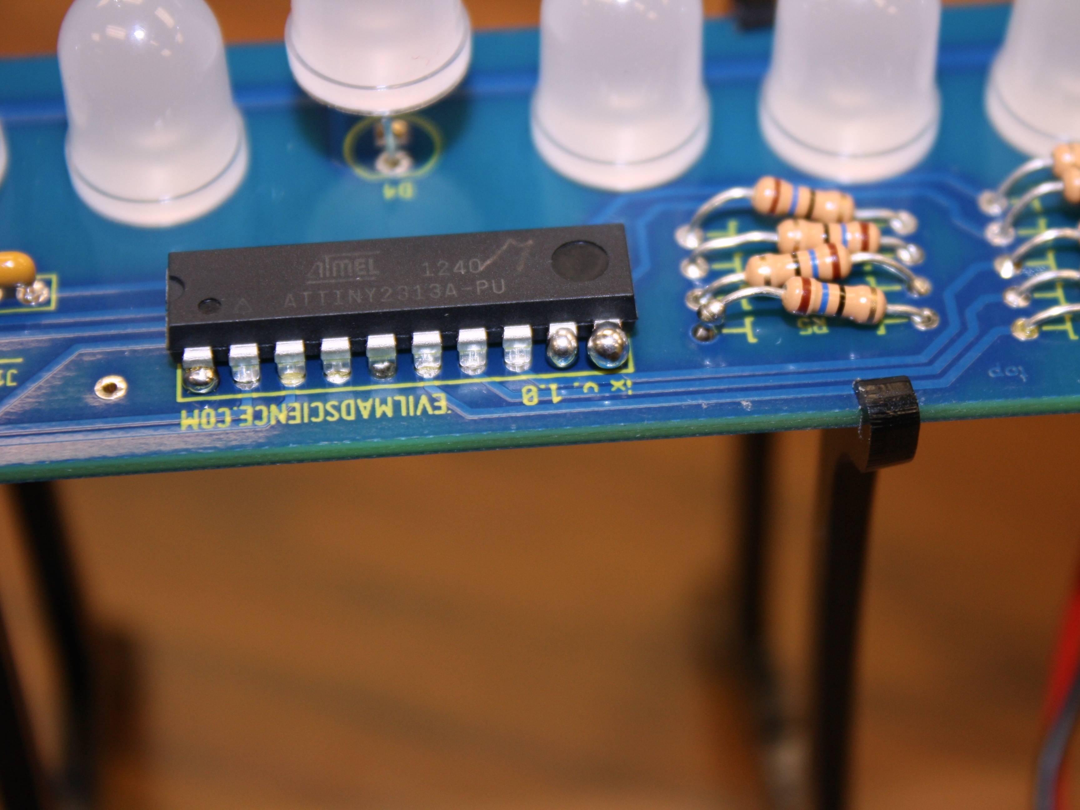
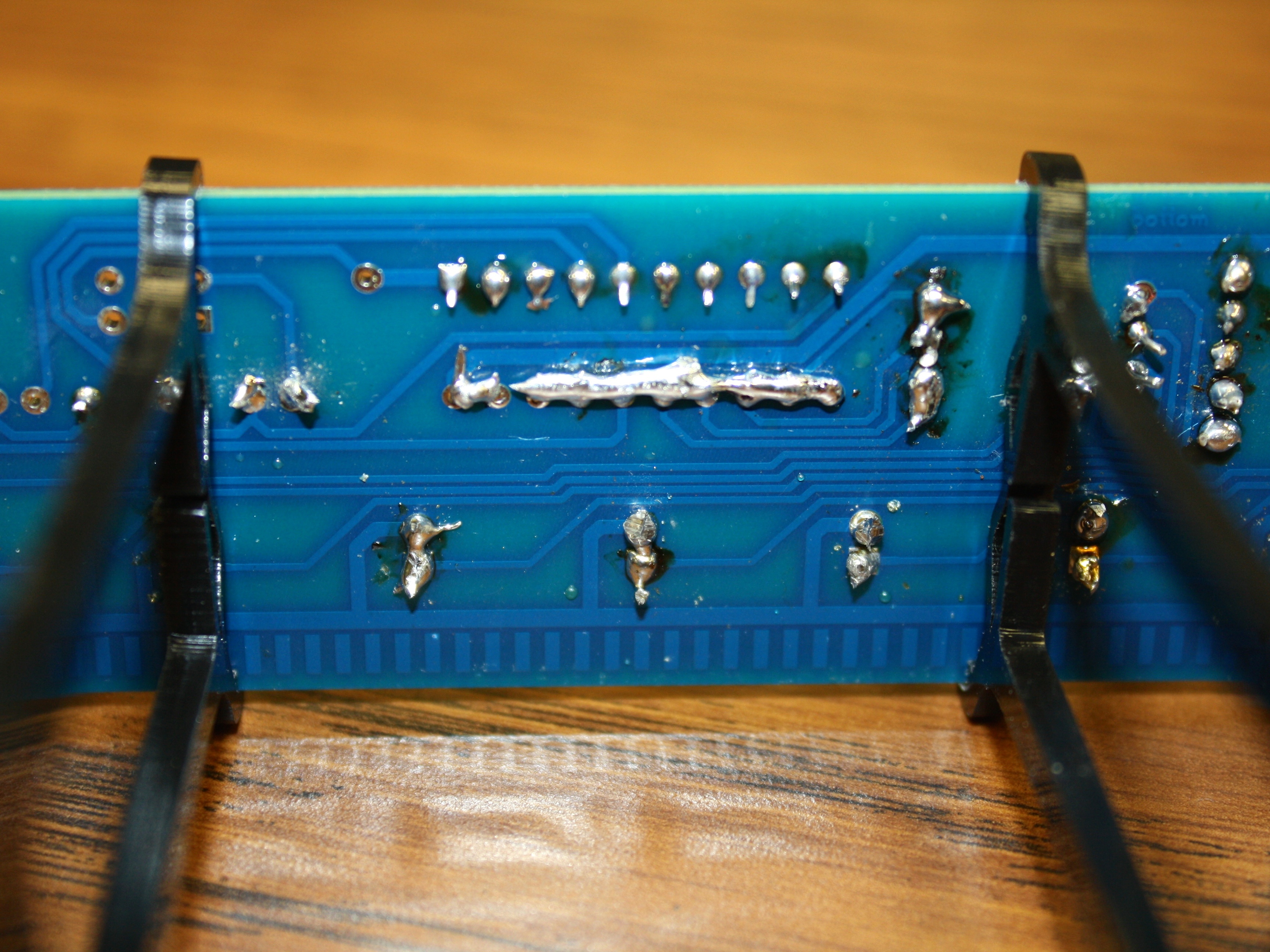
When soldering components from the bottom side of your circuit board, you can sometimes — if you feed enough solder into your solder joint for long enough — wick enough through the holes to form blobs of solder on the top side of the circuit board.  You can see these blobs here on four pins of the chip, as well as on some of the resistor leads. These blobs are highly desirable because you can make a “trick” circuit board where all of the solder joints look good from the bottom side, but there are actually short circuits on the top side of the board.

If you hone your skill well enough (or just get lucky), you may even be able to create an “invisible” short circuit between two pins of a component, fully hidden beneath the component. We’ve seen “secret” shorts like these under both chips and discrete components like capacitors and LEDs.

As an added bonus, it usually takes quite a while to wick this much solder through a joint. Most soldering guides recommend that you limit the time that you heat a component to just a few brief seconds. If you ignore that to get this much solder in the joint, you may have the added outcome of overheating the component and damaging it beyond functionality. That way, even if someone were to find and remove the short circuit, the component still wouldn’t work.

Untitled

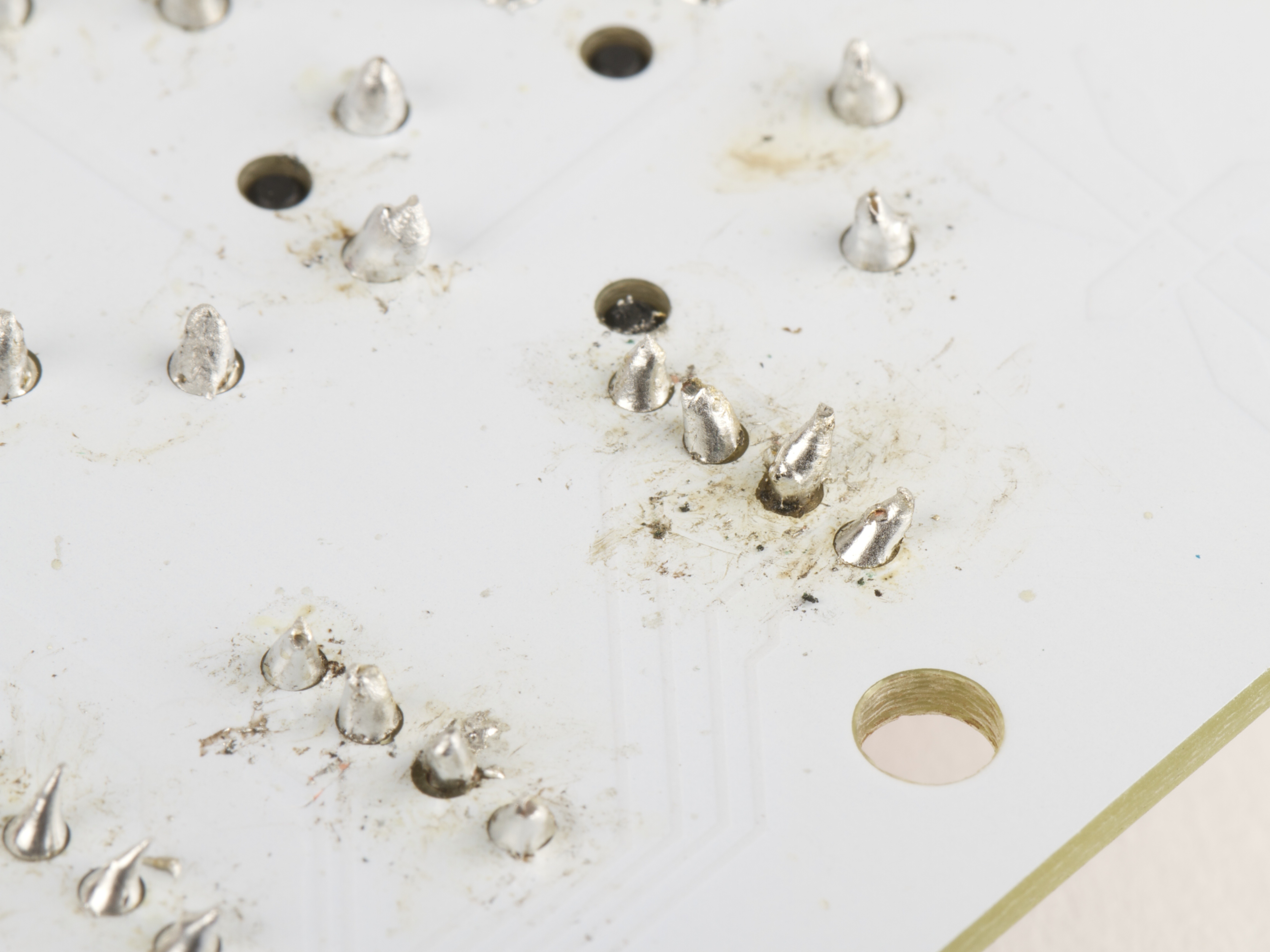
Expert mode! Going one step further, if you solder a given location on a circuit board for long enough or with enough pressure, you can actually delaminate the printed copper pad (trace) from the circuit board. The pad is usually a thin ring of copper around the hole with the pin that you’re trying to solder, or (on surface mount boards) simply a rectangle or oval of exposed copper that you solder to.

If you can manage to remove pads from a circuit board, then you remove the ability for a component to make electrical contact with the circuit board there. Sometimes, depending on the circuit, one can manually add a repair wire to fix the board. But in other cases, tearing off just a pad or two can destroy the circuit board beyond repair. (It’s also possible to break components this way, by overheating their leads.)

On single-sided circuit boards, you merely need to look at the pad once too many times to make it fall of. But on multi-layer (e.g., two-sided) circuit boards, pads tend to be resilient, so you’ve got to either heat them for quite a while or use pressure with the soldering iron to dislodge the pad. Again, this is “expert mode” territory, but the two most common techniques that we’ve seen for delaminating pads are (1) using a “cold heat” soldering iron (for which you may need to heat the joint for a very long time to get it to melt) and (2) repeatedly soldering and desoldering components at the same location.

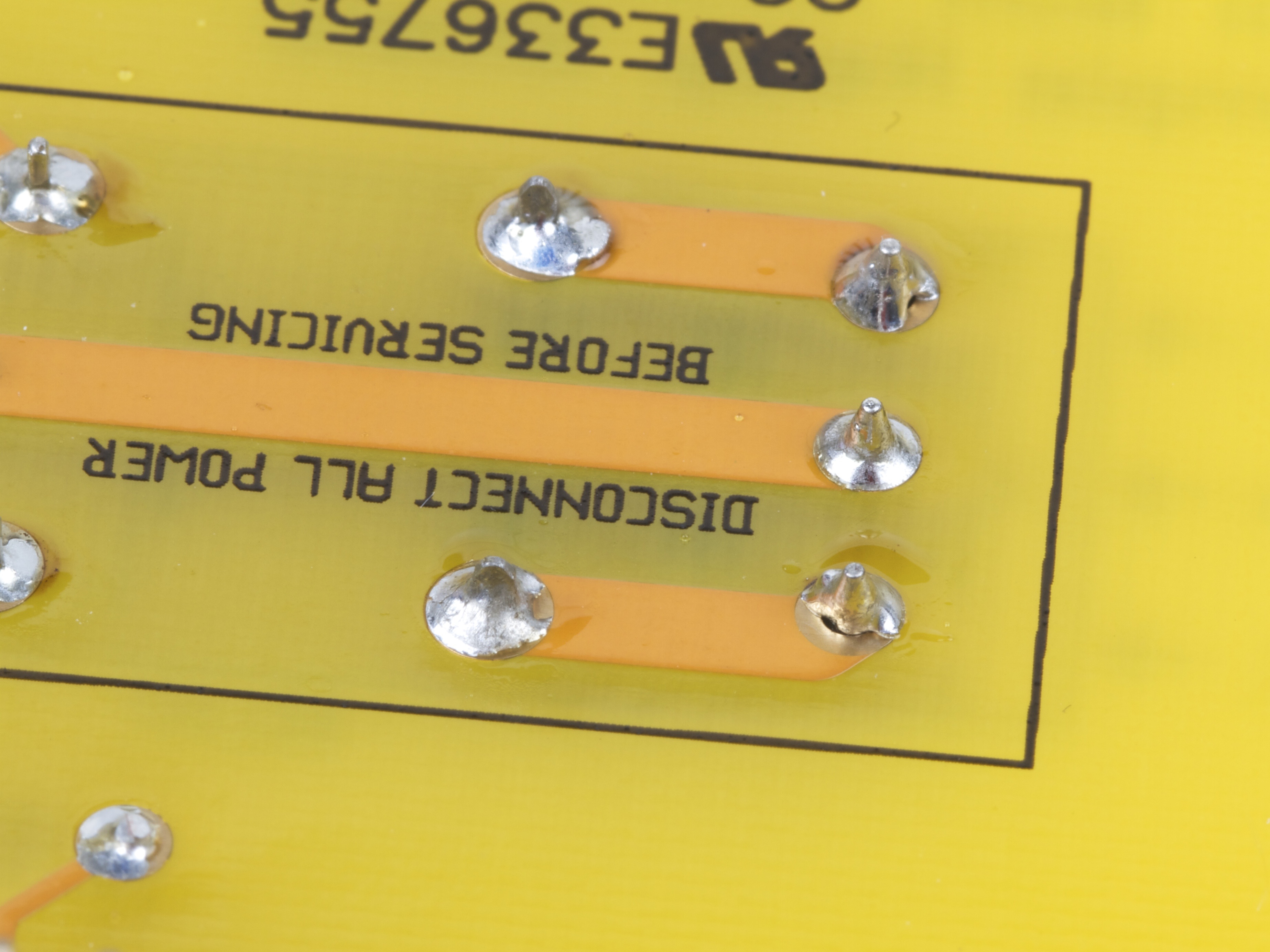
In the photo above, the pads have been torn off of the circuit board at two of the solder points (both ends of one resistor). Rather than having the solder flow down to a smooth meniscus there, the solder forms a blob that sits above a mysterious dark circle at those two points— the exposed circuit board substrate.

Untitled

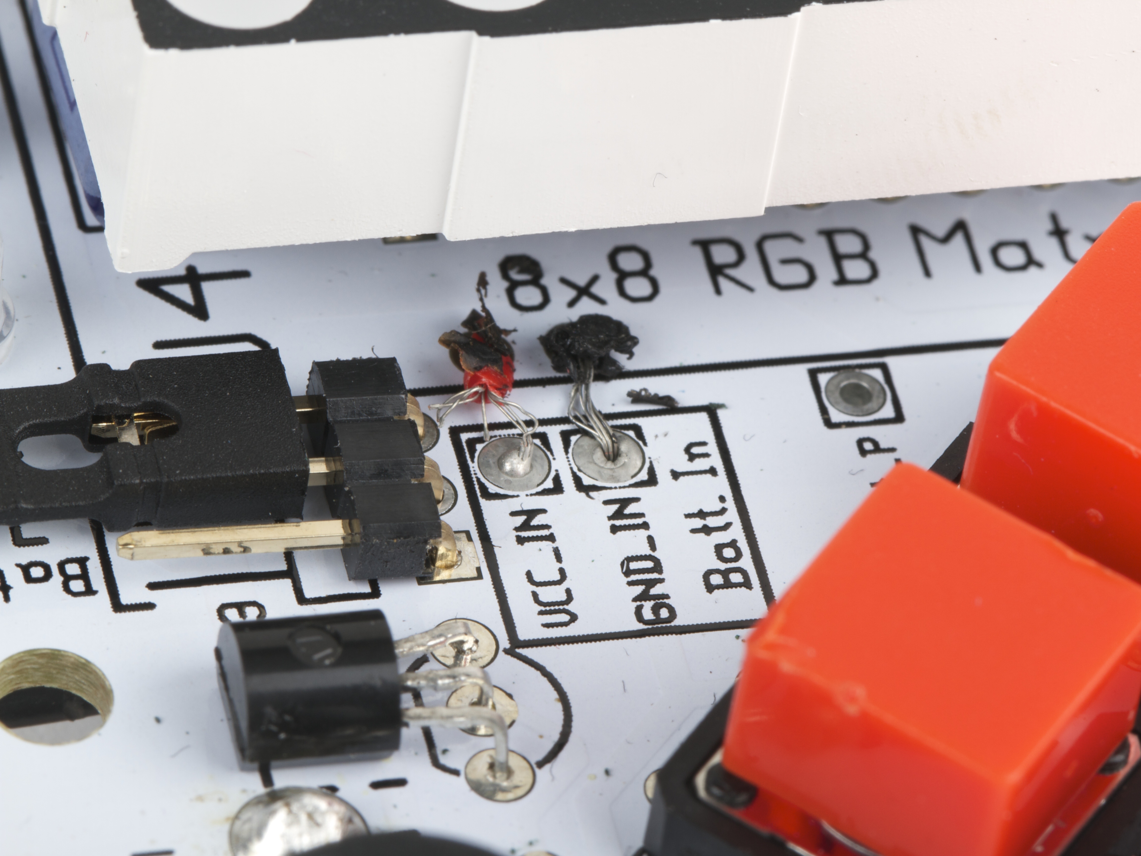
Here’s another example of what can happen when you heat a board for long enough. The two wires (red and black) from a battery holder are coming up through wide clearance holes next to the “8×8” marking, and then are soldered back down to the VCC_IN and GND_IN locations in the “Batt. In” section.

The insulation around the two wires has been melted back (almost back to the wide clearance holes) from long overheating, and the wires themselves have been frayed until there are just a couple of fine strands making all of the electrical connections. Added bonus: Stray strands like these can help to cause intermittent short circuits, when the wires get bumped.

Untitled

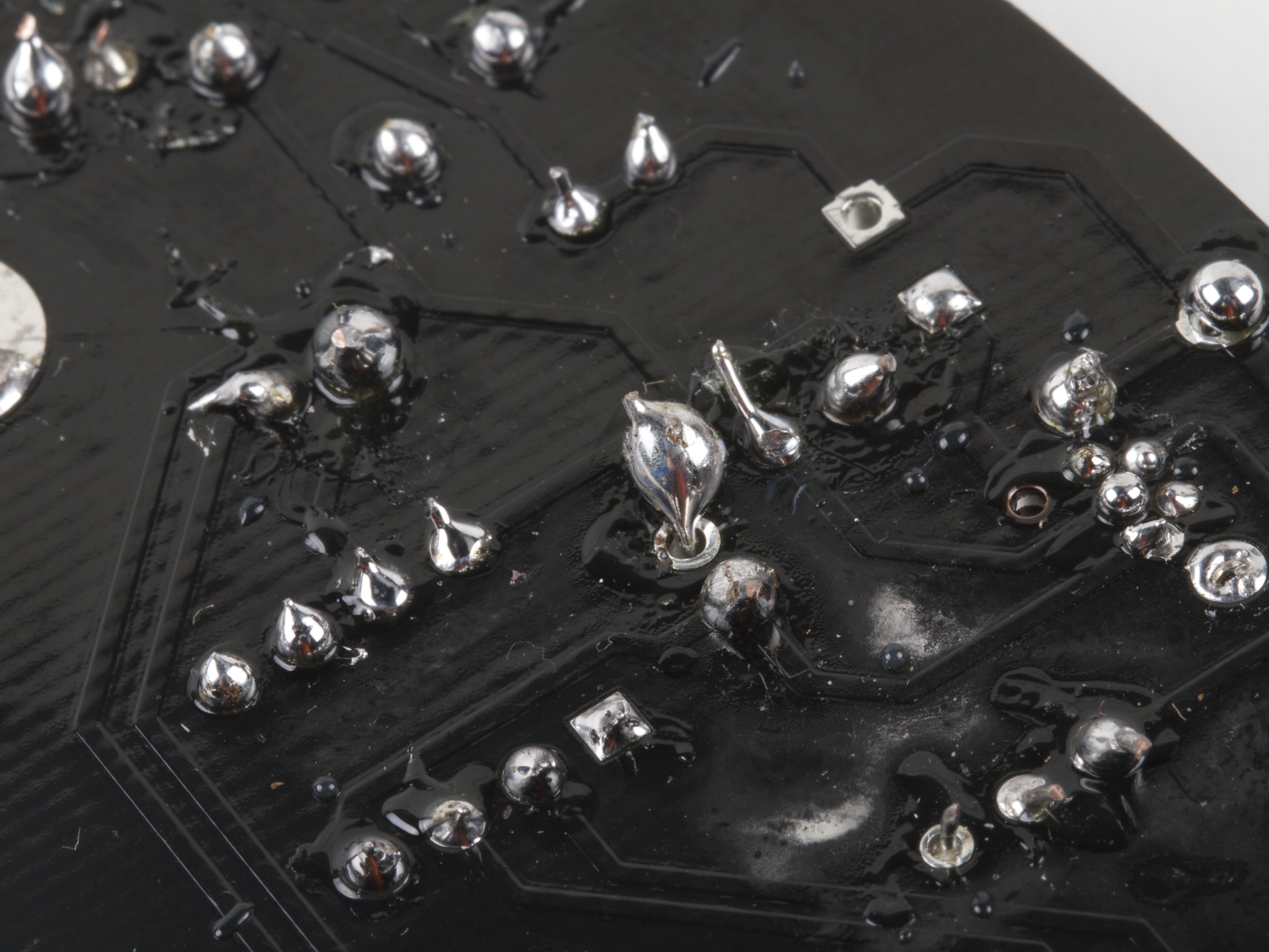
Soldering guides will often try and steer you away from making “blobby” solder joints with excess solder, but there’s clearly no good reason for this.  If a little solder is good, surely more is better!

Some of the blobby solder joints (like those at at the lower left) are shaped like onions grown over the integrated circuit pins, making it impossible to see how (or even, if) the joint actually contacts the circuit board. Others — like the giant gravity-defying inverse silver teardrop in the center — seem to hover in mid-air above the circuit board, deftly managing to avoid contact with the plated through-hole of the circuit board.

image

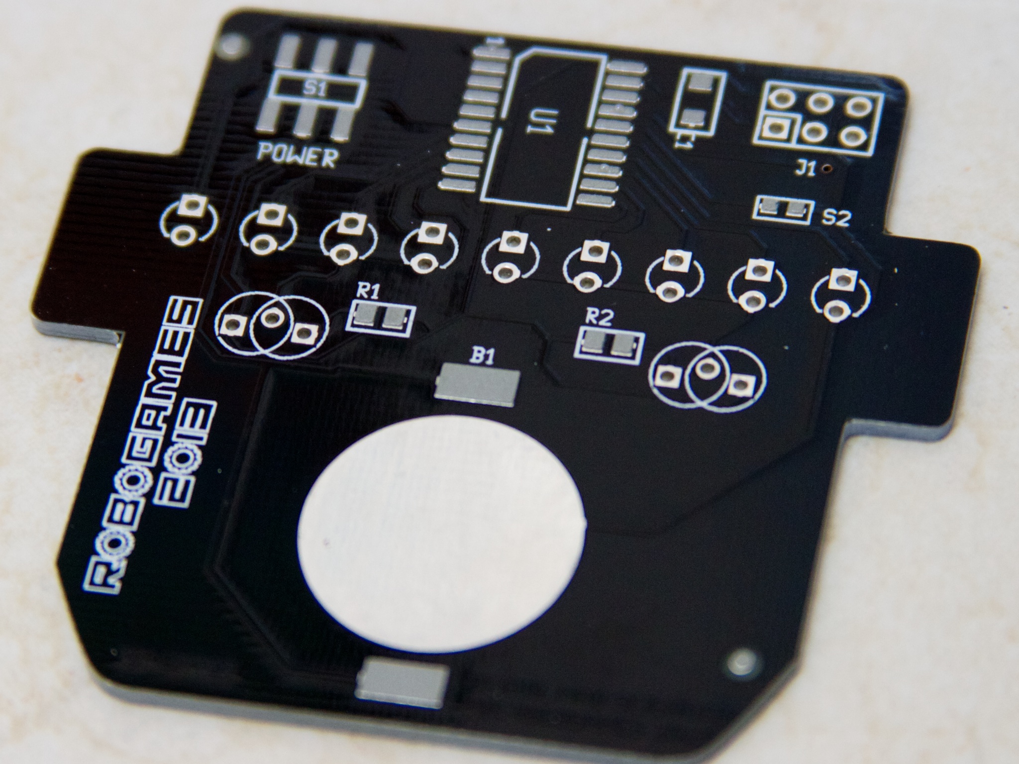
Keeping the component leads long and using blob-style solder construction can also help you to protect your intellectual property, by obscuring your circuit design from prying eyes. Spaced along the left edge of this circuit board, you can see that there are eight LEDs wired up… or are there? By lumping the two pins for a given LED under a single blob of solder, no one will ever be certain! (Also worth noting: this technique may have some side effects on the functionality of those LEDs.)

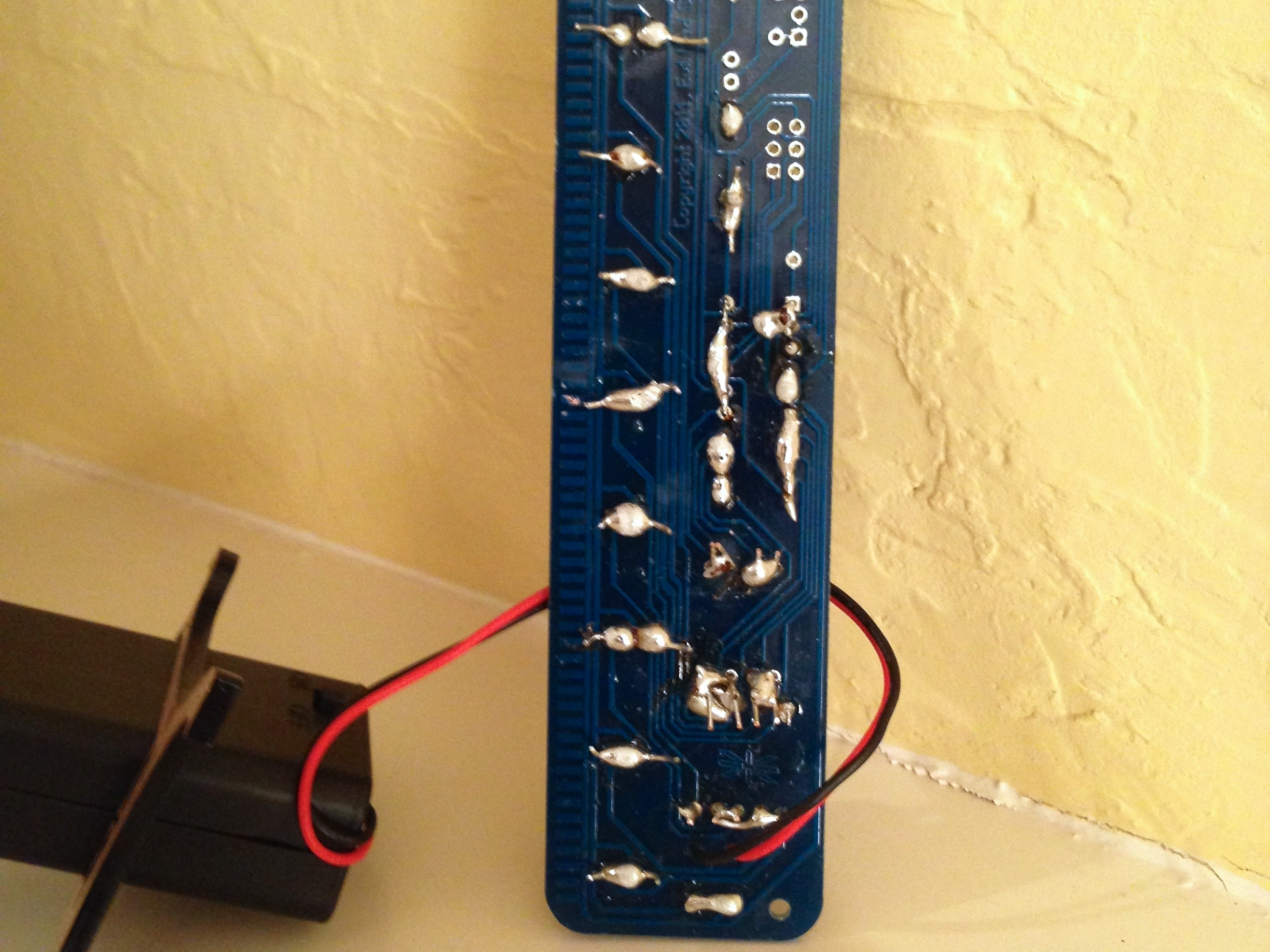
The very lowest solder joint on this circuit board is where the power and ground wires (red and black) are attached from the battery holder. Note that these two wires have been soldered together. “Shorting” the power and ground together like this is a classic technique to protect a circuit from damage due to unwanted charging or static discharge. (Note, however, that if the battery is switched on with its leads shorted together like this, the battery itself will also discharge quickly, get very hot, and possibly even explode.)

023

Here’s another related technique: If you solder together multiple pins of your microcontroller, you can connect to all of those pins at once, ensuring that no one pin steps out of line, and that all of the pins will work together in perfect digital harmony.

Got any other favorite examples of “novel” soldering techniques? Let us know in the comments or in the flickr group, and we’ll do another roundup sometime!

We would like to sincerely thank the helpful individuals who kindly granted us permission to use their photos and also those who allowed us access to their boards for photography.

From the Mailbag: Understanding the Homopolar Motor

Wes wrote in to say:

I am an Electrical Engineer (graduated May ’72, Texas Tech U), but I never saw or even heard of a homopolar motor until last week, when I saw an electric motor made from four parts on National Geographic’s program, “None of the Above“. When I first saw it, I figured it must be a hoax. A DC motor had to have a commutator and two magnets.

Only when I was browsing around in Wikipedia did I find an article on the motor. I happened to have everything I needed, so I built one, not really expecting it to work. To my great surprise, it spun up to a few thousand RPMs in seconds. I read Wikipedia’s theory of operation, but it didn’t make sense. Today, I came across your wonderfully clear and simple explanation, and now I understand the motor perfectly.

I simply cannot thank you enough for your drawing and explanation.

Thanks for writing in— we’re glad to hear you enjoyed learning something new! The instructions for making the motor and the discussion of how it works are in our articles:

Basics: AVR Target Boards and Arduino Compatibility

Diavolino
Gary writes:

I have fallen in love with your Diavolinos – thank you!
My question: does the “Simple target board” allow for the 6-pin FTDI Friend hookup to upload sketches? This is quick and easy with the Diavolino. I’m new to reading circuits and stuff, and I cannot tell looking at the target board. It says to use in-system programmer, but I prefer to not buy another interface. Thanks!

Excellent question! It is certainly possible, but not as quick and easy.  Both the Diavolino and our ATmegaXX8 target boards boards use the same chip, usually the ATmega328P.  But, one might say that our ATmegaXX8 board is a simple AVR target board optimized for use with an AVR ISP programmer (like the USBtinyISP), whereas the Diavolino is a simple target board optimized for use with the FTDI interface.

XX8 Target Board

Versus a “bare” target board (with just the chip and power), there are four things that you would normally add, in order to use the FTDI interface to upload a sketch from within the Arduino environment:

Continue reading Basics: AVR Target Boards and Arduino Compatibility

Basics: Base Resistors on Transistors

highside-good

Our reader Jon wrote in with a question about our open collector tutorial:

I really appreciated the tutorial, and I was able to follow along and understand it very well. One question I had was – what is the purpose of the 1 kilo-ohm resistor that is connected to the base of the PNP transistor? Because when the open collector is ‘high’ then the base of the transistor is at 12 V and it appears the 1 kohm resistor didn’t affect anything, and then when the open collector goes ‘low’ then the base is connected to ground through the output of the SN7407. So basically, what would the difference be if there was no 1 kilo-ohm resistor at all?

And, that’s actually an excellent question, about something that we usually gloss over.

The short answer is that this is a “base resistor” that we use to limit the maximum current that flows through the base of the PNP transistor.  But, let’s take a look in a little more detail, and see what would happen if we didn’t have that there.

Continue reading Basics: Base Resistors on Transistors

A round up of our “Basics” articles

  SolarCircuits - 06
Soft Circuit Merit Badge01  g22023

Over the course of the past few years, we’ve been writing occasional “Basics” articles, about introductory topics in electronics and microcontrollers.  In the spirit of making things easy to find, we’ve now tagged them so that you can find them with this link, and we’re collecting them together in this index that will be updated from time to time.

Our “Basics” articles about electronics in general:

Additional “Basics” articles about working with AVR microcontrollers:

Basics: Picking Resistors for LEDs

5 mm warm white diffused LED

So… you just want to light up an LED. What resistor should you use?

Maybe you know the answer, or maybe everyone already assumes that you should know how to get to the answer.  And in any case, it’s a question that tends to generate more questions before you actually can get an answer: What kind of LED are you using? What power supply? Battery? Plug-in? Part of a larger circuit? Series? Parallel?

Playing with LEDs is supposed to be fun, and figuring out the answers to these questions is actually part of the fun.  There’s a simple formula that you use for figuring it out, Ohm’s Law. That formula is V = I × R, where V is the voltage, I is the current, and R is the resistance. But how do you know what numbers to plug into that formula to get out the right resistor value?

Continue reading Basics: Picking Resistors for LEDs

Basics: Blink an LED with an AVR

AVR Blink Blog Post

Getting an AVR to blink might seem like an incredibly difficult task compared to the usual Arduino blink, but it really isn’t! In this post we will be uploading a basic blink example to an ATtiny2313. This is perfect for projects where using an Arduino would be over the top. So let’s get started!

Continue reading Basics: Blink an LED with an AVR

Basics: Open Collector Outputs

SN7407N

One of the joys of working with basic digital electronics– and logic gate ICs in particular –is that it almost works like building with a set of Lego blocks: One output goes here, which connects to the next input here, and so forth until it does what you wanted.

If you’ve played with chips like these, you’ve probably also come across chips with “open collector” outputs. And if not, they’re worth knowing about. Open-collector outputs form the basis of a number of clever tricks for level-shifting and interfacing between different types of logic, and from logic to other types of electronic circuits.

In what follows, we’ll work with the SN7407N, which is one of the most basic ICs with open-collector outputs. We’ll discuss what it means to have “open collector” outputs, and show some of the different ways that they are used. Continue reading Basics: Open Collector Outputs