Category Archives: Science

AxiDraw used for developing techniques for bioprinting

Diagram of experimental setup with Axidraw and example results
Scientists working on developing techniques for bioprinting used the AxiDraw with a syringe in place of a pen as part of their experimental setup. They recently published an article they shared with us, saying,

We finally achieved what we planned with the Axidraw. It worked well! We made small patterns of hydrogel, millimetric, that we intend to use for seeding living cells.

It is always exciting for us to see people finding new uses for the AxiDraw. Thank you to Dr. Fitremann for sharing your results with us!

Windell and Lenore on the Embedded.fm podcast

Hilton's Aeolid

Elecia and Chris of Embedded.fm invited us to come back on the show for episode 317: WHAT DO YOU MEAN BY DISINTEGRATED?. We also had the added enticement of a low tide adventure after recording.

Lenore had been on the show back in 2014 for episode 40: MWAHAHA SESSION, and Windell was on the following year when The Annotated Build It Yourself Science Laboratory was published for episode 124: PLEASE DON’T LIGHT YOURSELF ON FIRE.

We enjoyed the conversation immensely. We wandered from talking about our kits, to plotter art, to PCB art, even to seaweed. The tide pooling afterwards was wonderful as well!

Watch the transit of Mercury with us!

Solar telescope and binoculars set up in front of Evil Mad Scientist sign.

Tomorrow morning is the transit of Mercury, which is where the planet Mercury is visible directly in front of the sun. This won’t happen again until 2032. If you happen to be in Silicon Valley and would like to see the transit with your own eyes, please join us tomorrow morning (weather permitting—assuming that the sun is out).

What: Viewing the transit of Mercury
When: 8:30 – 10 am Monday, November 11, 2019
Where: Evil Mad Scientist, 1285 Forgewood Avenue, Sunnyvale, CA 94089

We’ll be setting up solar binoculars and a telescope with a solar filter so that we can safely watch Monday morning. It will take Mercury about 5 and a half hours to cross in front of the sun, and we’ll be watching the last hour and half. We’ll start viewing at 8:30 am until the end of the transit at about 10 am.

Astronomy Cookies

Galaxy, globular cluster and nebula cookies

We love any excuse to create science themed food, and we had a blast brainstorming our contribution to “Astro-Gastro” contest at the annual member meeting at the Fremont Peak Observatory. We settled on some of the things we love to show visitors to the observatory: Galaxies, globular clusters, and nebulas.

Cinnamon Pinwheel Galaxy

Cinnamon Pinwheel Galaxies are inspired by palmiers. They are made with puff pastry that is coated in cinnamon sugar and rolled up, sliced and baked. The recipe is identical to palmiers except that you first fold the pastry over itself a little further than halfway, and then roll up from the folded edge to create the spiral pattern that shows when you slice them.

Globular Cluster Cookie

Chocolate Globular Clusters start with the same chocolate graham crackers we used for our Edible Asteroids project.

We iced them with a chocolate icing derived from a recipe for Black And White cookies from Baking Illustrated. Melt 2 oz unsweetened chocolate in double boiler. Bring 2 Tbsp light caro syrup and 3.5 Tbsp water to a boil in small saucepan. Remove from heat and stir in 2.5 cups powdered sugar and 1/4 tsp vanilla. Stir icing into chocolate in the double boiler. You may need to reheat the chocolate icing in the double boiler to keep it at a good consistency for spreading.

Immediately after spreading the icing on a cookie, very slightly moisten the top of the icing with water. You can either dip a finger in a dish of water and smooth a bit over the surface of the icing or use a water mister to give it a very light spritz. The water on the surface will make it sticky enough for the sprinkles to adhere to. Drop small white non pareil sprinkles over the center of the cookie. We used a small funnel held over center of the cookie, to create a dense cluster in the middle, and fewer and fewer as you reach the edges.

Meringue nebulas

For the Meringue Nebulae, we divided a batch of meringue into two, and colored half of it with black food coloring. The other half we split again and colored with red and blue respectively, stopping before it was fully mixed in to allow for some color variation. We spread the blue meringue along one side of a piping bag, and red along the other. Then we filled the middle with the grey. We piped the mixture out with a #12 icing tip in a wavy, uneven fashion. Using two different sizes of non pareil sprinkles made it look like there were stars of different brightness in our nebulae.

Meringue Nebula closeup

Other astronomers brought moon rock smores, almond asteroid cookies, and an Orion constellation cake. We’re tickled that the Cinnamon Pinwheel Galaxy won the contest against such fun competition.

Astronomy Outreach at the Fremont Peak Observatory

Observatory building on top of hill with trees behind

For the last year and a half, we’ve been volunteering with the Fremont Peak Observatory Association (FPOA). It is located in Fremont Peak State Park, just above the mission town of San Juan Bautista, which is where Hitchcock’s Vertigo was filmed.

Lenore with telescope behind

Challenger (behind me in the picture above) is the name of the main telescope at FPOA. It is a 30 inch diameter Newtonian telescope on an equatorial mount, built by telescope maker Kevin Medlock. It is a lot of fun to move a big scope like this around to point it at different things in the sky. It is great for looking at deep sky things like galaxies, nebulas, and star clusters.

The members are incredibly welcoming and dedicated to amateur astronomy and science outreach. The organization has free (except for the state park parking fee) public programs on Saturday nights from March to October when there isn’t a full moon. The schedule for upcoming programs is posted on the website.

telescopes set up on pads

During public programs, we set up some of the smaller telescopes that belong to the observatory, and members sometimes bring their own telescopes to set up. This means there are usually multiple telescopes pointing at different things to see, and even folks who can’t use the ladder for the big Challenger telescope will be able to look to the stars.

Observatory building and sunset

It is a joy to be there the first time someone sees Saturn or Jupiter, or even the moon through a telescope. There is something special about seeing those things with your own eyes. The sky is dark enough—in part due to the ocean fog frequently socking in the towns below—that the viewing can be spectacular, and later in the year the Milky Way streaks across the sky.

Some members bring their gear up to the observatory to do astronomical imaging. We haven’t done any astrophotography other than cellphone photos through the eyepiece that don’t do justice to the view you get. We’ve seen incredible views of the planets, the Andromeda Galaxy, the Hercules Globular Cluster, the Ring Nebula and many other wonders. And perhaps best of all, we’ve had the privilege of sharing those views with visitors.

Uncovering the Silicon: μL914

At the 2018 Bay Area Maker Faire, our project Uncovering the Silicon showed off a number of simple and complex integrated circuits (with rather large feature size) under the microscope. We had a great time helping visitors look at the features and get a glimpse of what’s inside those black box integrated circuit packages. To take this to the next level for this year’s Maker Faire, we decided to try and close the loop; to take one simple integrated circuit and elucidate its workings well enough that visitors to our booth will be able to see every single component of the circuit, understand their function, and relate it to the macroscopic behavior of the chip. For this, we picked what turns out to be a rather obscure chip: the Fairchild μL914, which is a dual 2-input NOR gate. This chip belongs to the resistor–transistor logic (RTL) family.

uL914 IC closeup in circuit

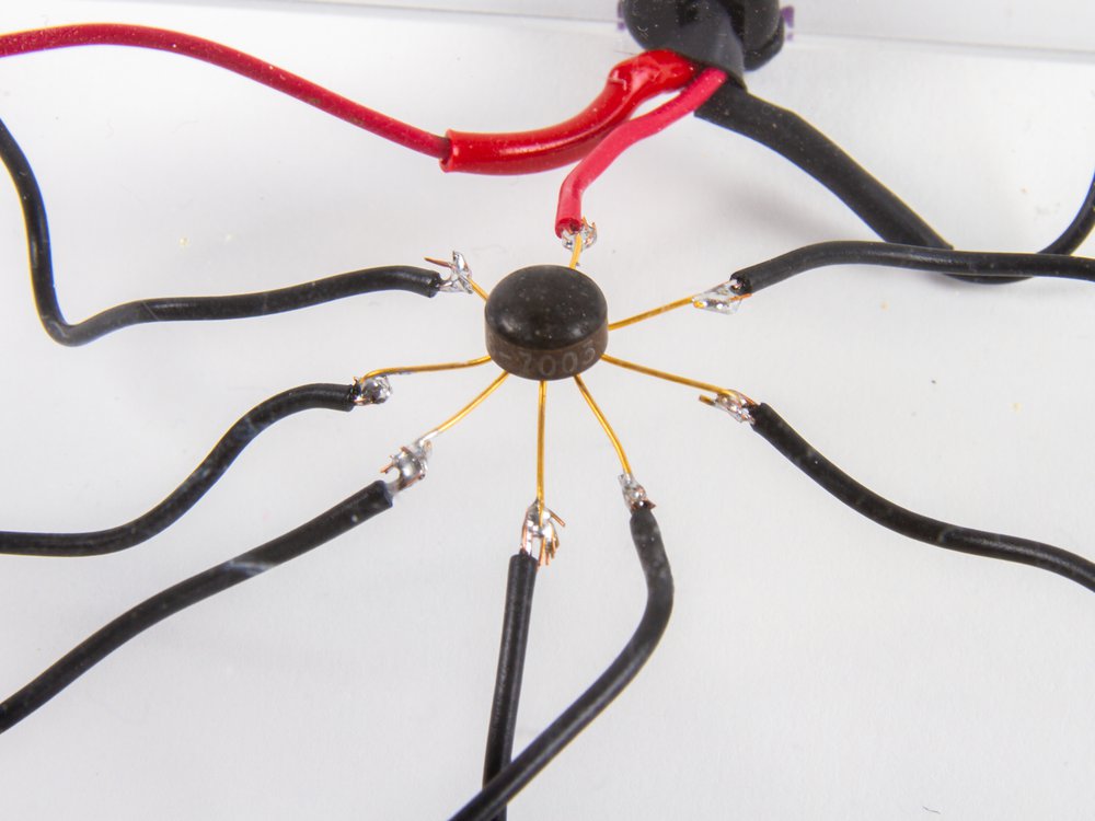
Here’s what the chip looks like. It’s in a funny old “glob-top” can package with eight leads.

pinout

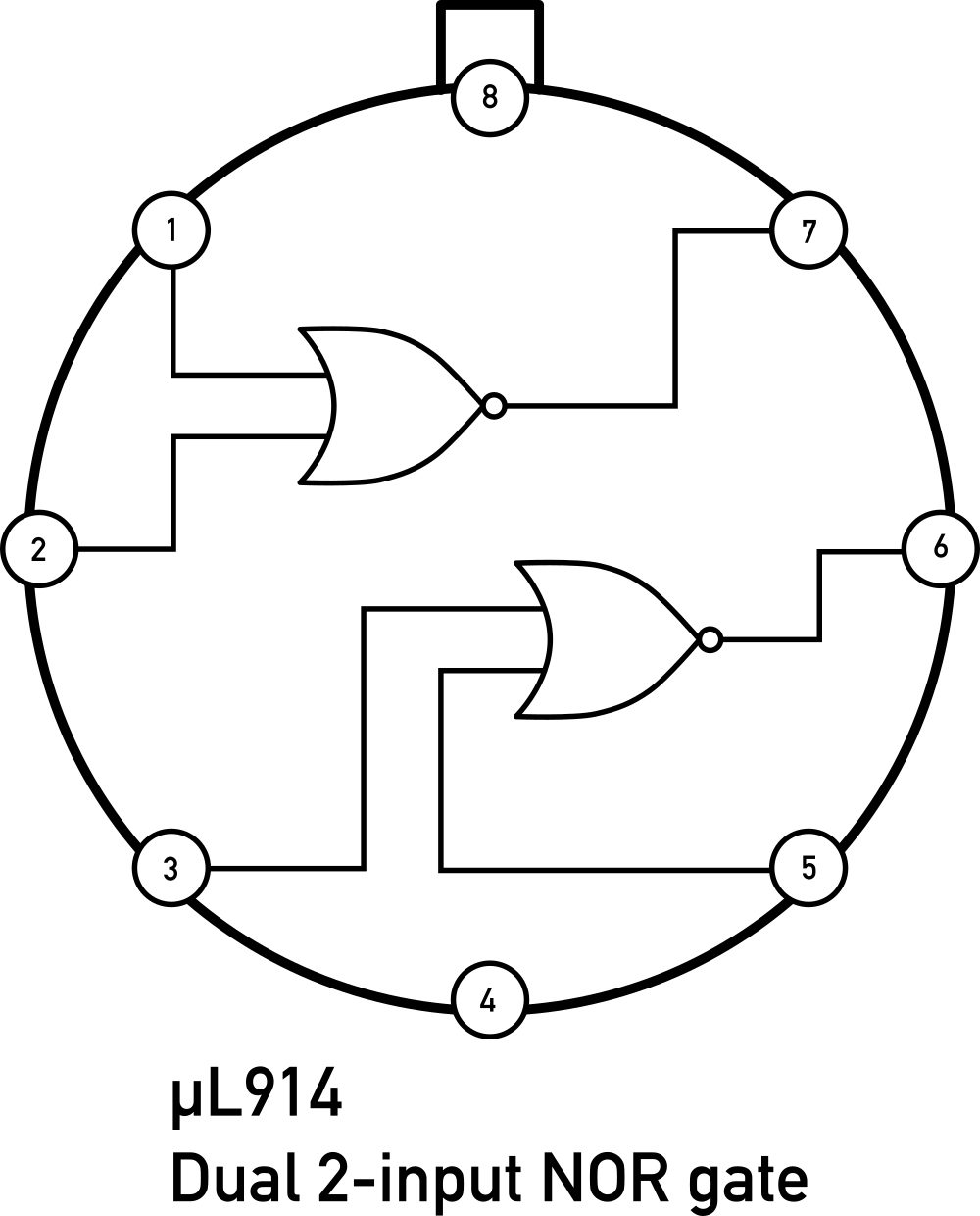
Here’s the pinout; there are two NOR gates in the chip, plus power and ground.

uL914 IC package circuit with switches and LEDs

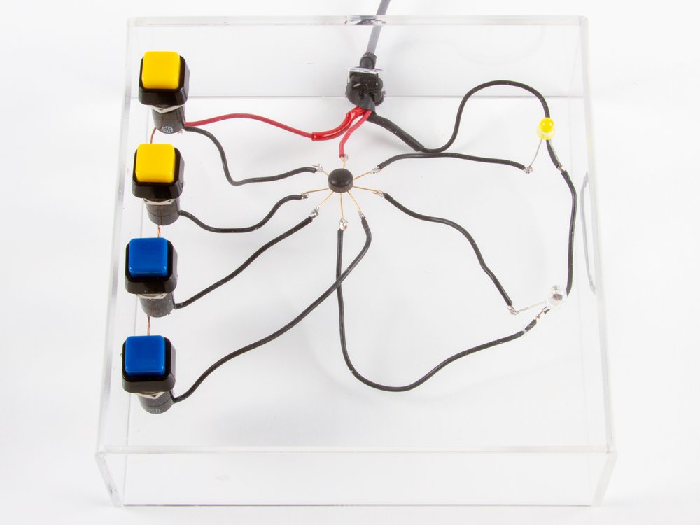
Ken Shirriff built a circuit with the chip to demonstrate its functionality. When we push either of the two buttons for one of the gates, that LED will turn off.

Schematic

Here’s the schematic diagram, adapted from the original datasheet. If you look at the left side, if either of those inputs goes high, the transistor pulls the output low.

uL914 dual 2-input NOR gate die photo

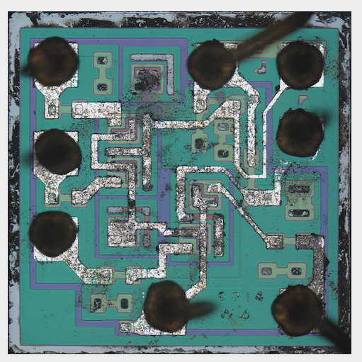
John McMaster decapped a few of the chips and sent us a die photo. He made a video about the process — no small feat. We’ll be bringing one of these bare chips and a microscope (equipped with both eyepieces and a camera) to Maker Faire.

For the macroscopic scale, we approached visualizing this circuit from a couple of angles: the physical structure of the chip, and the electronic structure of the circuit.

uL914 die model render

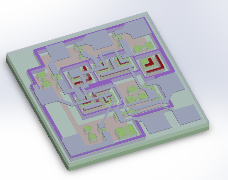
Eric Schlaepfer used the die photo to model the structure of the chip in CAD.

uL914 PCB version

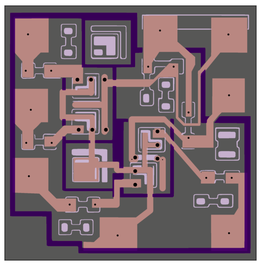
Simultaneously, Ken designed a printed circuit board version for use with discrete components that maintained the same structure as the IC.

Individual transistor acrylic model Individual transistor acrylic model

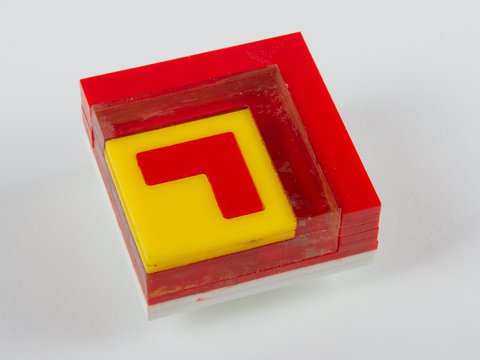
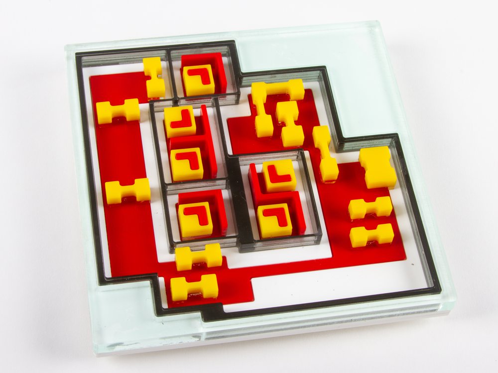
Working from Eric’s CAD model, we built a single NPN transistor model from layers of colored acrylic. If you lift it up, and look through the transparent middle layers, you can tell that the emitter (red) is embedded into the top of the base (yellow) and does not go all the down way through it. (Transistors like these are planar: The emitter is above the base, and the base is above the collector.)

The top layer of this little model has labels for the collector, emitter and base. It is removable so that the layers of the model can be more easily inspected.

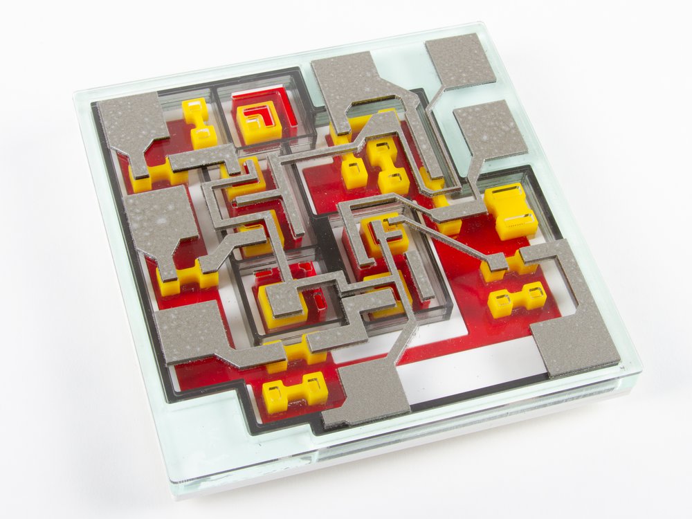
The model of the chip die includes a transparent cover representing the oxide layer, and that supports the metal layer with the wire bond pads on the edges.

One of the reasons that this particular chip is educational to look at is that there are a few unused components on the die. There are two unused transistors: one of them is unconnected, and the other is shorted. There are also several unused resistors (resistors are the dogbone shapes). The unconnected and unused components are easier to see, and provide a visual example that is useful for understanding what the connected components look like under the metal layer.

It is also fun to imagine what other circuits could have been made with different connections.

We glued most of the layers together, but left the top two layers removable so that it is easier to see the internal structure when the top is removed.

(Aside: we left out most of the epitaxial pocket material, because even though we used transparent acrylic to represent it, the layers of the components are much more visible without it present.)

Acrylic chip model top with metal layer

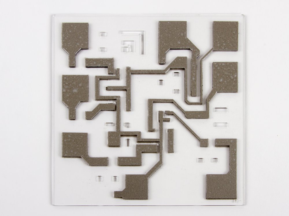
There are cutouts in the oxide layer where the metal layer connects to the circuitry below.

Acrylic chip model with hot glue bond wire example

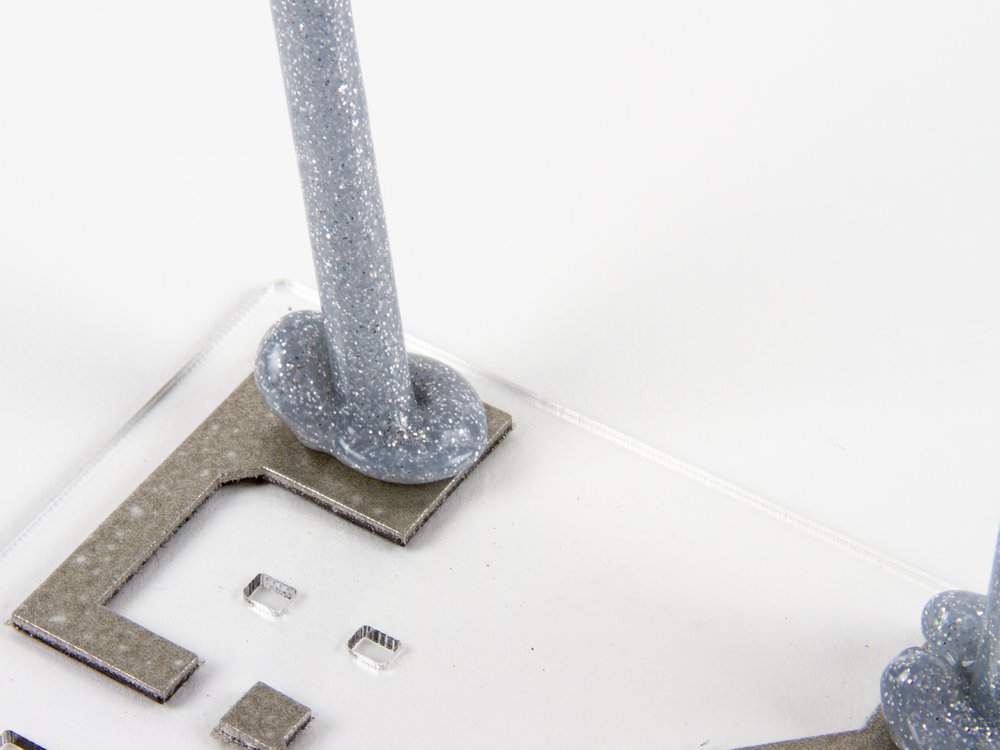
One of the most noticeable things you see when you look at this type of IC under the microscope is the bond wires. We’ve used silver glitter hot glue sticks to represent them.

bond wire closeup

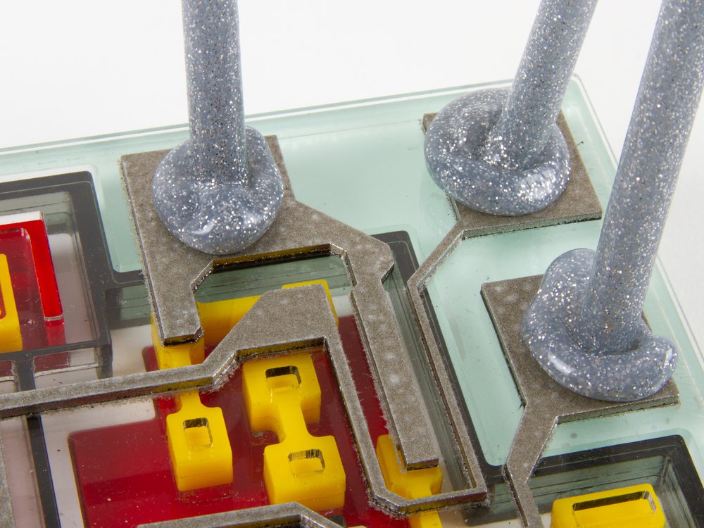
The glob of melted glue represents where the wire is bonded to the pad.

Acrylic chip model with hot glue bond wires

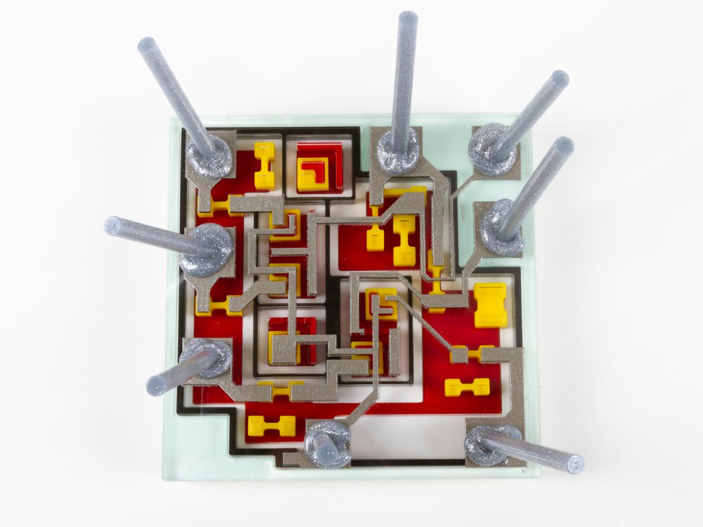
When you look straight down on the model with its glitter bond wires, it looks very similar to what you’ll see in the microscope.

Acrylic model legend

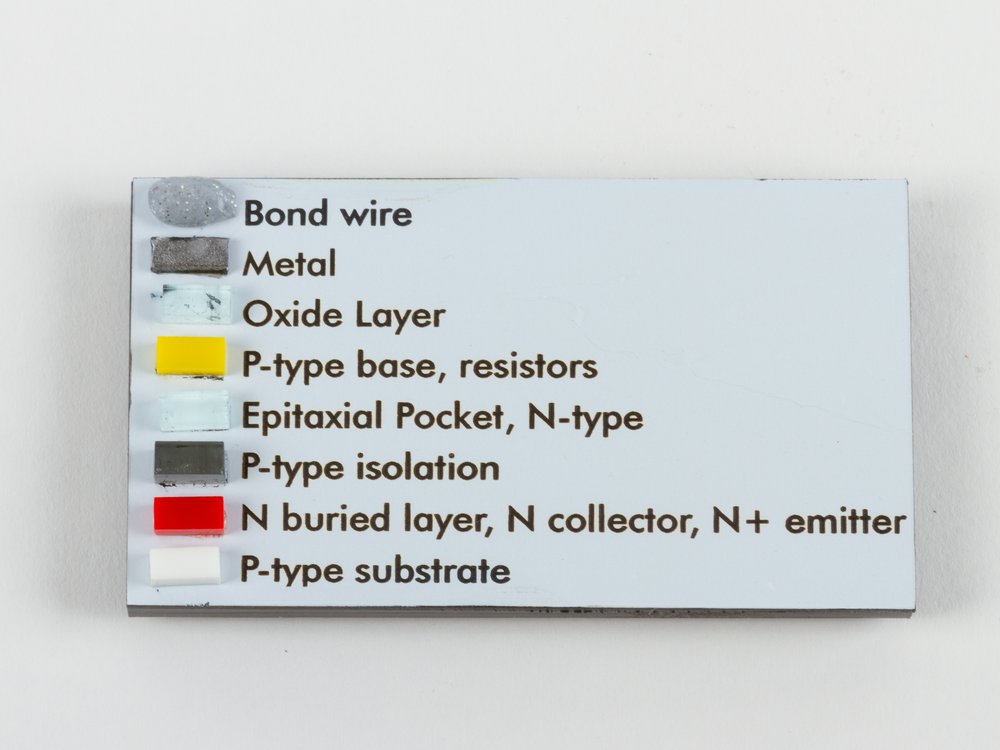
To round things out for our acrylic model, we made a physical legend to make it easier to identify all of the parts of the model.

uL914 discrete version switch and LED circuit

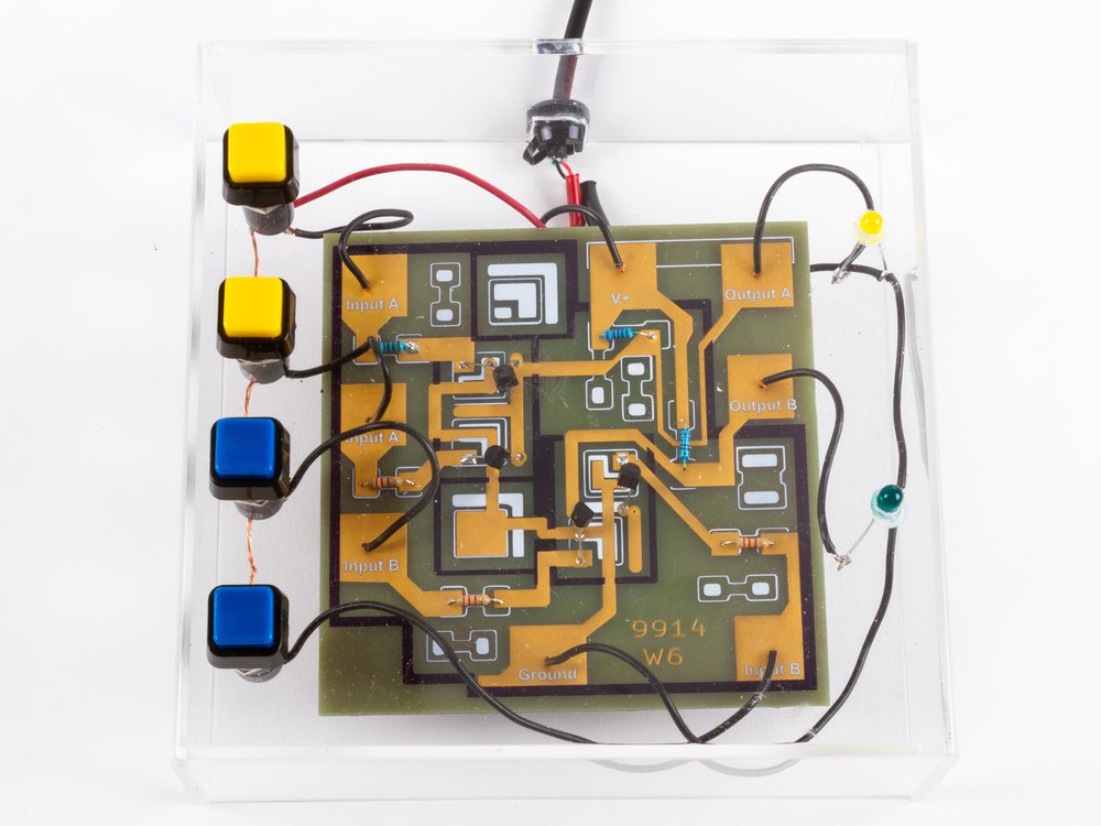
Once Ken got his PCBs back from our friends at OSHPark, he built it up with the same example circuit.

discrete circuit closeup

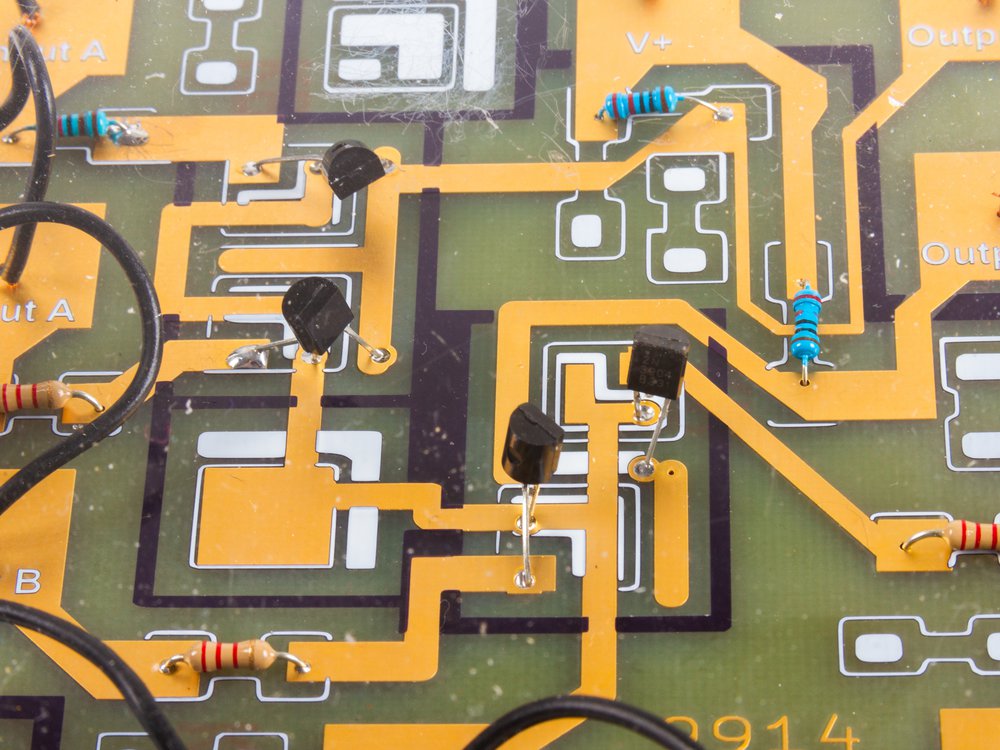
The PCBs turned out beautifully, and it’s great to see the familiar discrete packages on the enlarged circuit. Ken has published the PCB design on Github.

We hope to see you at Maker Faire this weekend!

Bonus: Ken laid out some hypothetical alternate metal layers to use the same die to create different chips.

Bonus video: Mike from Hackaday came to visit our project at Maker Faire and got a great video explanation of our project with Windell. He also wrote it up for Hackaday.

Science Hack Day SF

I will be at Science Hack Day SF giving a lightning talk on Creative Off-Label Tool Use featuring some of the cool and unusual ways people are using AxiDraw and other tools we make. I’ll also have an AxiDraw in the hardware hacking area to play with.

Science Hack Day is October 27-28 and is free, so register now!

P.S. If you’re doing something interesting and science or research related with your AxiDraw, please let me know!