


Recently we put together this interactive Game of Life display as an educational adjunct for a new exhibit by the San Jose Museum of Art on the works of Leo Villareal. Leo primarily works with light sculptures, and we’re very excited to see (and participate in) the exhibit, which opens this Friday.
We put together a video showing off the project, embedded here:
(If you can’t see the video here, click here to visit the youtube page.)
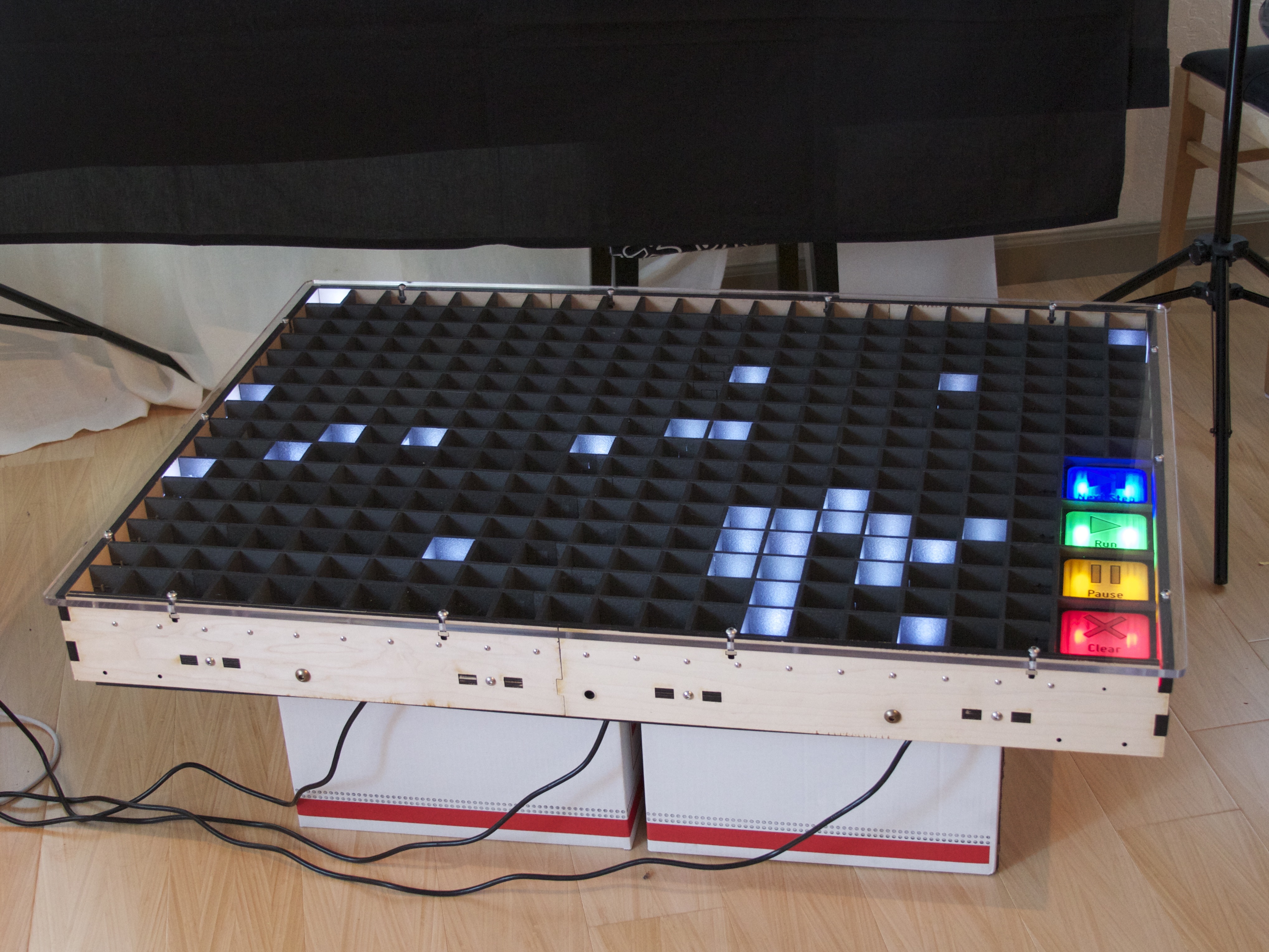
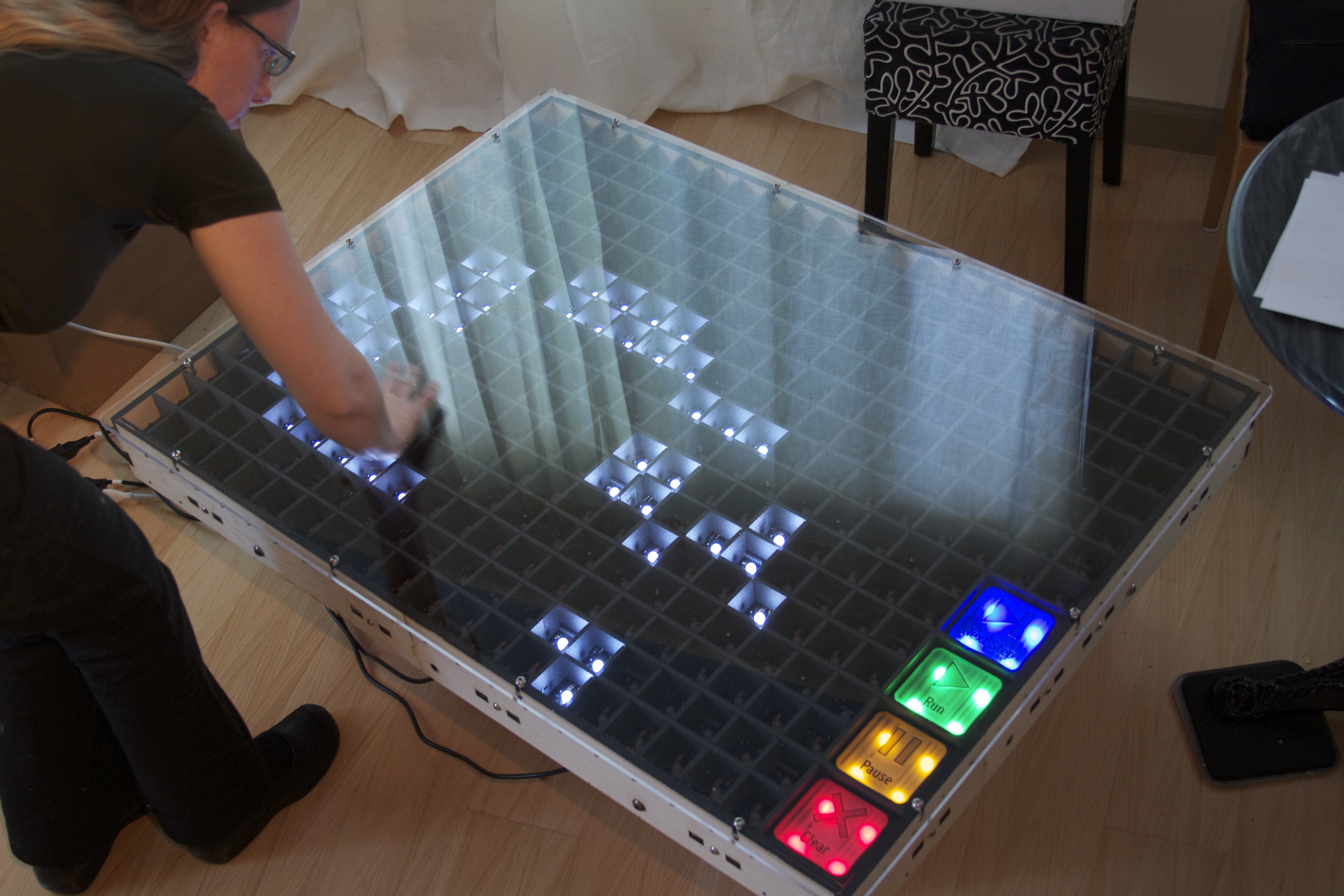
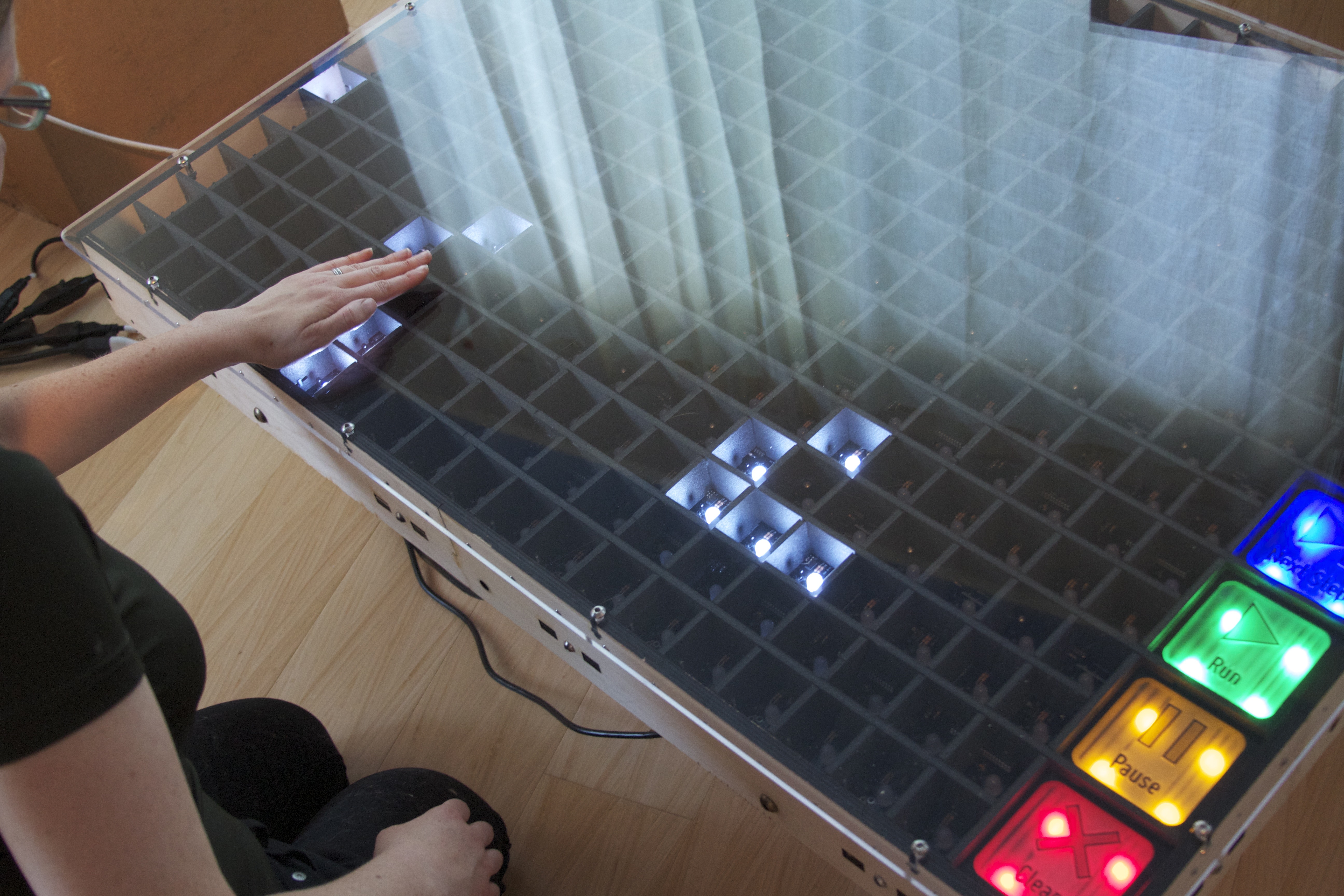
Prior to its installation on a wall at the museum, we set the exhibit on some office boxes to try it out.
As you can see, it’s pretty big. The interactive surface is 32 x 44 inches, and has LEDs spaced on a 2-inch grid. There’s also a “control” section on the lower right corner.
Up close, the display is constructed of medium-size printed circuit boards that are tiled together.
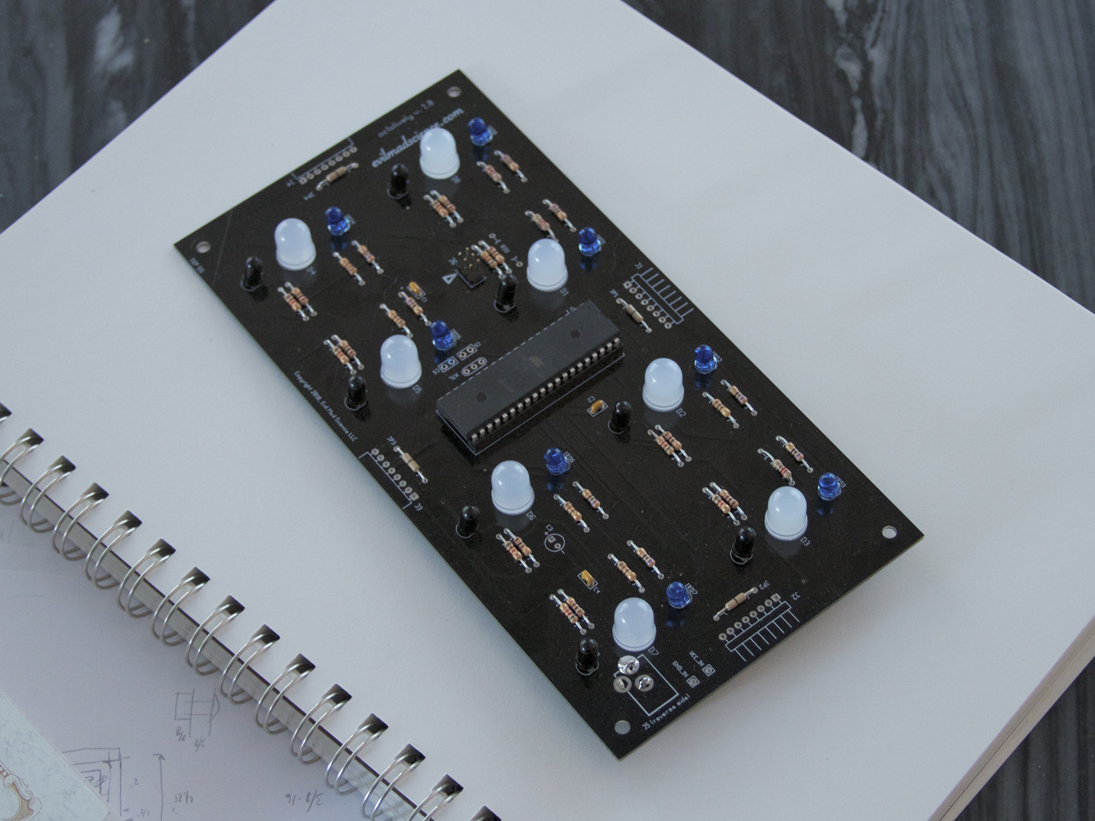
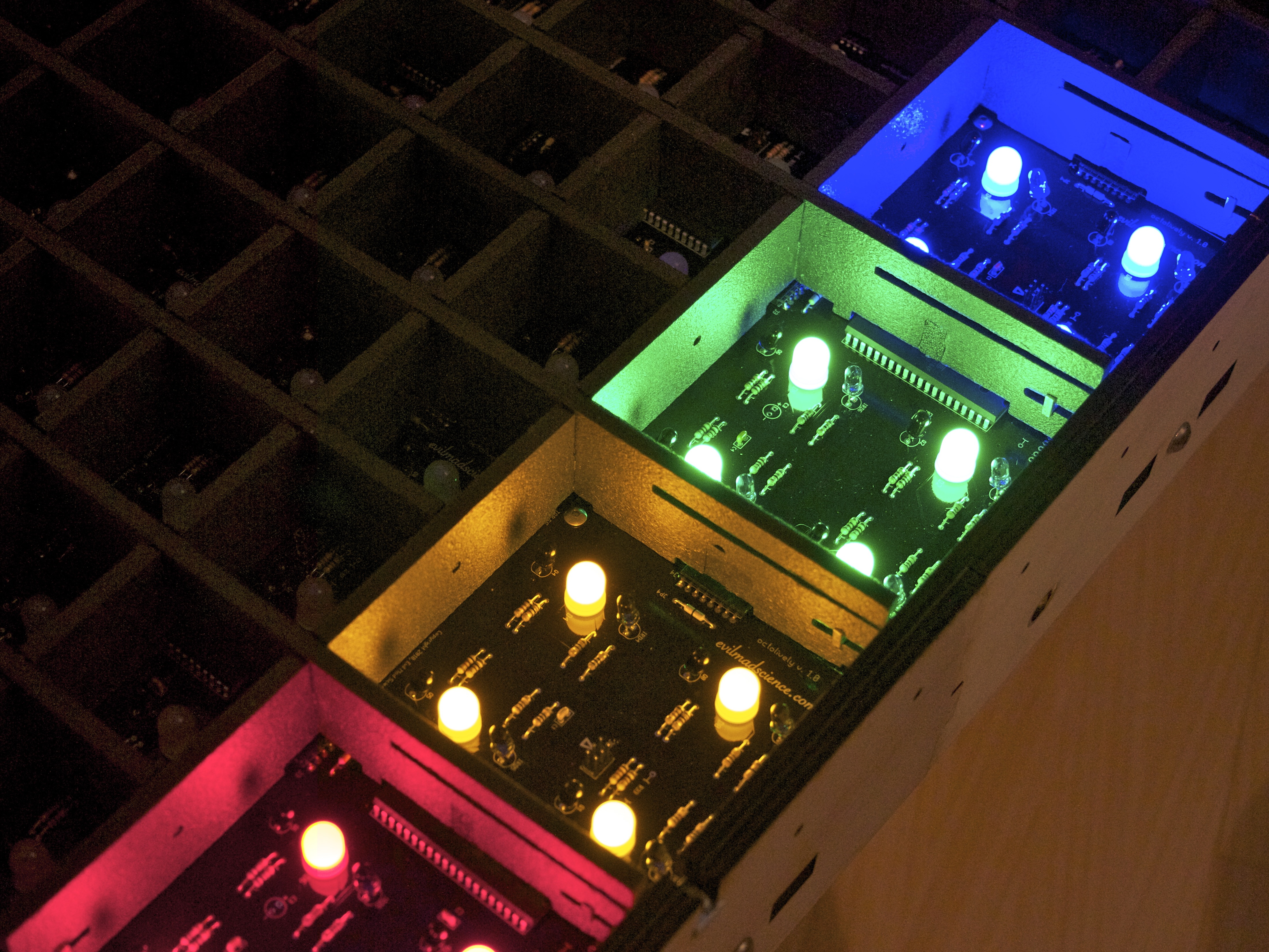
This printed circuit board was designed for the project. It’s 4×8 inches and supports eight 10 mm diffused-lens LEDs.
Each LED site is intended to be an independent “cell” for the game of life, and each one has its own sensor. The sensors are active infrared proximity sensors, consisting of an infrared LED (tinted blue) and infrared phototransistor (tinted black). This pair of components detects reflection off of nearby objects, such as your hand when you reach out to touch the display.
An Atmel AVR ATmega164P microcontroller manages the sensors and communicates with neighboring boards. The communications protocol is a low-grade hack: a “bit bang” protocol, not so different from the scheme used on the Dropout Design/Adafruit Game of Life Kit. Communications and power are shared between neighboring boards using edge connectors.
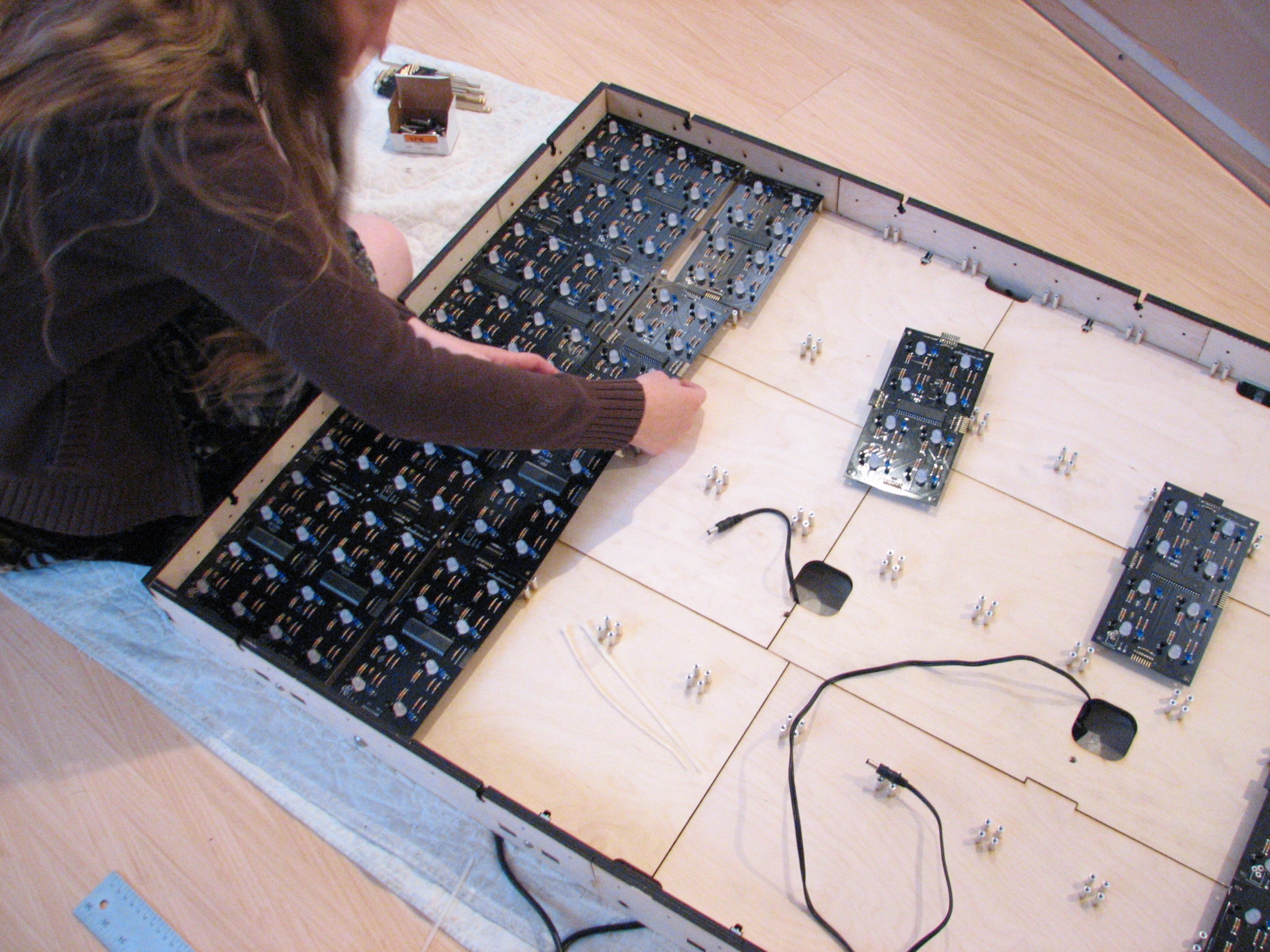
The circuit boards are snapped together with their connectors, and then installed on threaded standoffs inside the wooden frame.

It takes 44 of the circuit boards to fill up the display. While each circuit board is only moderately complex, the set of boards adds up quickly to about about 3000 electronic components and 10,000 solder joints.
Each board draws up to 200 mA of current at 5 V to run the processor, LEDs, and sensors, so the full set of boards draws up to 8.8 A. Because the edge connectors are not rated for currents this high, the display is actually separately powered in three sections, tied together by the common ground of the power supplies.
The individual cells of the display are isolated in a latticework 1.5 inches tall, made of black Depron foam. (Aside: Depron is amazing material. It’s a fairly rigid polystyrene, much like the core of standard foamboard. It’s remarkably rigid for its weight, relatively inexpensive, and cuts faster than almost anything else either with a hobby knife or laser cutter.) The latticework is necessary not only to define the cells visually, but also to prevent crosstalk of the infrared sensors.
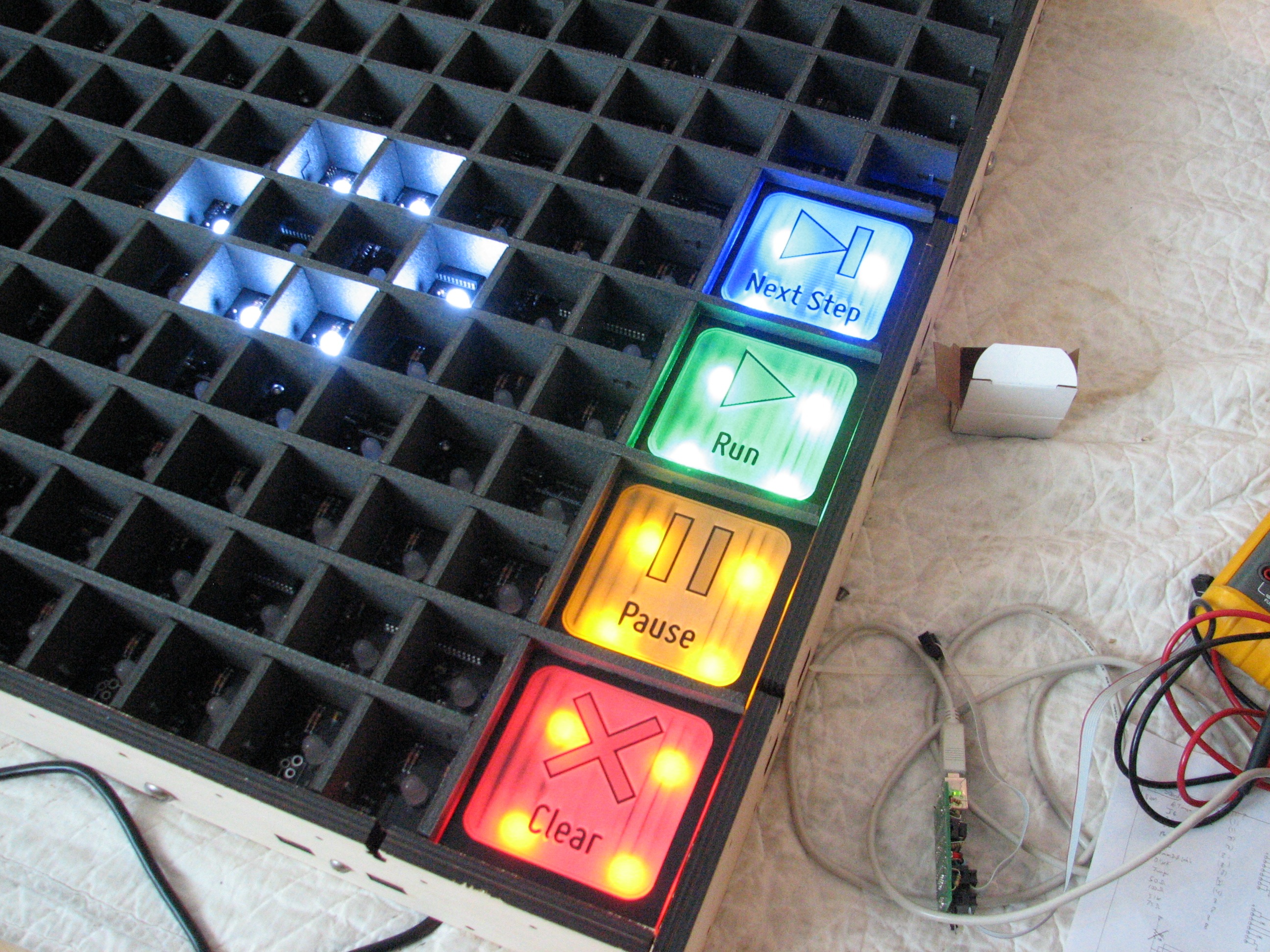
The four control “buttons” on the lower right (Next Step, Run, Pause, Clear) are constructed on two of the circuit boards, constructed identically to the others except for their LED colors:
These colored sections illuminate an engraved acrylic overlay that has the human-readable button text; the overlay is transparent to infrared, and only minor software changes are necessary to configure these sections as control buttons rather than cells.
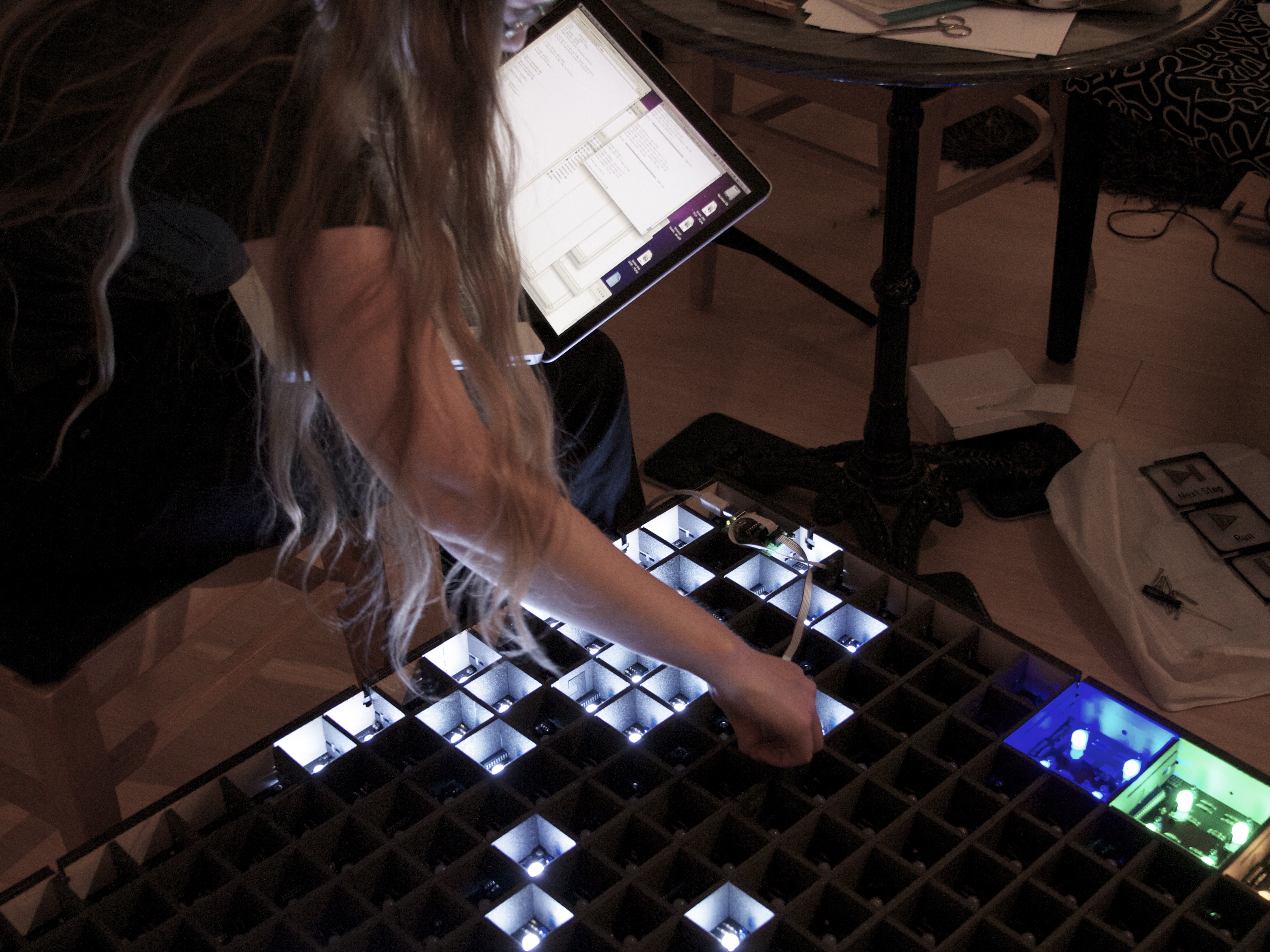
The downside of having so many independent boards: Each of the 44 boards had to be programmed individually. Fortunately each board has an accessible AVR ISP header, even with the lattice installed.
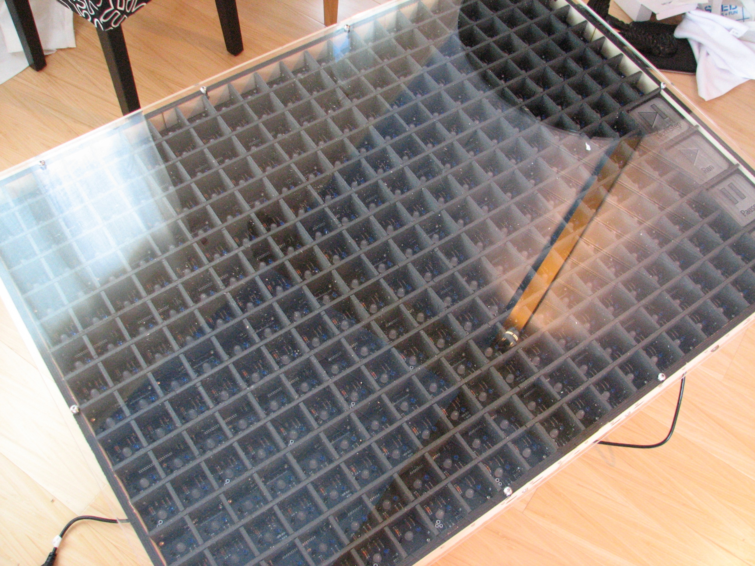
The top cover is 3/8″ thick clear acrylic, 34 x 46 inches. We had it made for us by conventional routing. It’s held in place by a few 1/4-20 button socket cap screws that connect to nuts in the wooden frame.
And that about covers it. The Leo Villareal exhibit starts this week at SJMoA. If you haven’t seen our video of this yet, please check it out.
If you haven’t played with Conway’s Game of Life, that’s definitely worth some time. You might start with a basic simulator and check out some of the more interesting details when you’re ready.
Obviously, the first thing I thought of when I saw it was "oh, look, a huge Peggy", but then when I saw that you were using IR transmitters and receivers to make it interactive, I knew that it wouldn’t fit in the Peggy’s form factor. So then I thought it was something more akin to the Interactive LED Panels, which is close, but not totally accurate.
Given the sheer number of parts, and the complexity of assembling the boards together while maintaining proper voltage requirements and such, I would imagine that we won’t be seeing this in the Evil Mad Science store any time soon, no?
I do have a more serious question, though: since this appears to have been designed with expediency and time constraints in mind over power consumption (and, honestly, for an exhibit, brightness should probably win out over power consumption concerns anyway), is there a more "elegant", less "bit-banged" way to accomplish such a project with fewer parts, but with the same level of flexibility (like the interactive LED panels)?
Will any parts of this project end up trickling out as open-source items, will any of the techniques and lessons learned from this project end up filtering out to other projects and into new products, or is this simply an extension of the Dropout/Adafruit Game Of Life kit?
Also, on a very serious note, I’ve noticed that you use the edge connectors to share power and data between boards on a number of projects. Any chance that the edge connector idea could be made into its own more detailed blog post some time in the future?
Looks great, as always! :) Keep it up!
>Obviously, the first thing I thought of when I saw it was "oh, look, a huge Peggy"
There’s actually very little in common with the Peggy/Meggy architecture: no multiplexing, no drive transistors, no LED driver chips. Also, as there’s only "peer to peer" communication, it’s not easy to program a single large image to appear on the tiled display.
> So then I thought it was something more akin to the Interactive LED Panels
Yes, these are a low-voltage, digital, relative of our interactive LED panels.
> Given the sheer number of parts […] I would imagine that we won’t be
> seeing this in the Evil Mad Science store any time soon, no?
The actual parts count is pretty low per board, it’s only when you build so many that it adds up like this. We will probably design an open source project and/or kit around some aspects of this project. We need to spend some time playing with the software to figure out what this circuit is really best at in practice. We don’t intend to release a "game of life kit," of course– there’s already a good one out there.
> […]this appears to have been designed with expediency and time constraints
> in mind over power consumption
Power consumption was actually a concern. The power budget per board (200 mA) essentially allows one IR LED to be on at a time and all eight LEDs at 20 mA. Lower power means less brightness, ultimately. 200 mA per board allows 20 circuit boards to be connected together with one 4 A, 5 V power supply– that’s not bad, actually, for such good brightness.
> […] Is there a more "elegant", less "bit-banged" way to accomplish such a project
> with fewer parts, but with the same level of flexibility (like the interactive LED panels)?
Bit banging is elegant its way, requiring almost zero parts for bidirectional communication in four directions at once. However the software required to support it has very high overhead, particularly since we built these without crystal oscillators– each processor’s clock can vary in frequency +/- 10%, which means that we need to do a lot of work in synchronization and error detection. We’re actually using a 1N1 protocol at fairly low baud rate, with a parity bit on each command.
Depending how much less oppressive we can make the software requirements, we maybe able to do more interesting things with it. Depending on application, there are some other interesting tricks that can be used. For example, the IR LEDs can be used as sensors alone, without phototransistors. The data rate is typically lower, though, so it wasn’t actually a good choice for the game of life project.
Towards the future, we’re probably evolving towards more complexity and elegance at the same time. The xmega chips that we’ve been playing with have multiple serial ports that can make communicating with neighbors much easier. The parts count and BOM cost will be higher, but the process will be more natural.
> Any chance that the edge connector idea could be made into its own
> more detailed blog post some time in the future?
Interesting idea; we’ll think about it.
Windell H. Oskay
drwho(at)evilmadscientist.com
http://www.evilmadscientist.com/
So awesome. You guys make the best stuff. Great work!!!
Was it tricky to get a good "button press" from the reflectance measurement?
Yes. :) We tried a few different models, and settled on one that models a hand approaching the sensor– a steadily increasing signal over a certain range of time.
Windell H. Oskay
drwho(at)evilmadscientist.com
http://www.evilmadscientist.com/
Buggy software?
Has anyone else noticed that at around 1:46 in the video that stationary square patteren randomly starts to dissolve despite none of the other lights getting close enough to actually effect it?
As we discuss in the video, the infrared proximity sensors are not perfect, and add a bit of randomness to the grid. You can see several other "false positive" events in the video, including one that we directly point out. Part of the problem is that we did this demo in a room well lit by sunlight– meaning that our shadows are good sources of IR as we walk around.
Windell H. Oskay
drwho(at)evilmadscientist.com
http://www.evilmadscientist.com/
I was about to say, I watched the video without sound, and I figure that once this is mounted on a wall in an exhibit under significant amounts of artificial lighting, most of the "oops, I didn’t mean to ‘press’ that button" issues will go away altogether.
Any randomness that pops in can be attributed to a desire for "mutations", as some GoL’s are programmed to have. ;-)
It’s not a bug, it’s a feature! :-D
I’m curious, if slightly ignorant. Could the entire assembly be wired to "loop"? For example, when a glider flies off the top border, could the edge connectors be wired to the bottom border to allow the glider to reappear rising from the bottom? Are these circuits complex enough to allow for that?
Yes, it could be wired up that way. :)
Windell H. Oskay
drwho(at)evilmadscientist.com
http://www.evilmadscientist.com/
This is awesome! I definitely did notice the "scanning" of the image(read: refreshing artifacts) Is there any way you could update the display faster for quicker play rates and make the "scanning" disappear?
Certainly possible. The program right now specifies a delay of 50 ms before propagating its message. It’s much more of a design decision than a technical artifact.
Windell H. Oskay
drwho(at)evilmadscientist.com
http://www.evilmadscientist.com/
Life is always a fun thing to explore technology with. When I was writing drivers for a graphics chip maker, I abused the logic operations on our BitBlt hardware to make a Life generator that would put out 1 generation of life in like 7 Blits. It was able to go faster than the screen refresh at 1600×1200.
Please, give the names of IR emitters and transistors you used.
I really want to play with my homebrew IR sensor.
Thanks!
I second this question only in the sense that I’m thinking of creating an IR break-beam detector for a different project.
Then again, there are matched-pair IR emitter/phototransistor detector pairs available at The Shack that would probably work just fine for prototyping in small quantities (at least, assuming one has a Shack store close to them with this kind of stuff in stock. Of the two in my town, only one really has any appreciable IC stuff in stock any more…).
Hi
My client are participating in an exhibition and would like to have a game section on their booth beside displaying their products (car) to promote their booth. I would like to know if you would like to put your game and promote your product in Malaysia.
Thank you
Diana Smith
Pls reply to my email dianawahid@hotmail.com