


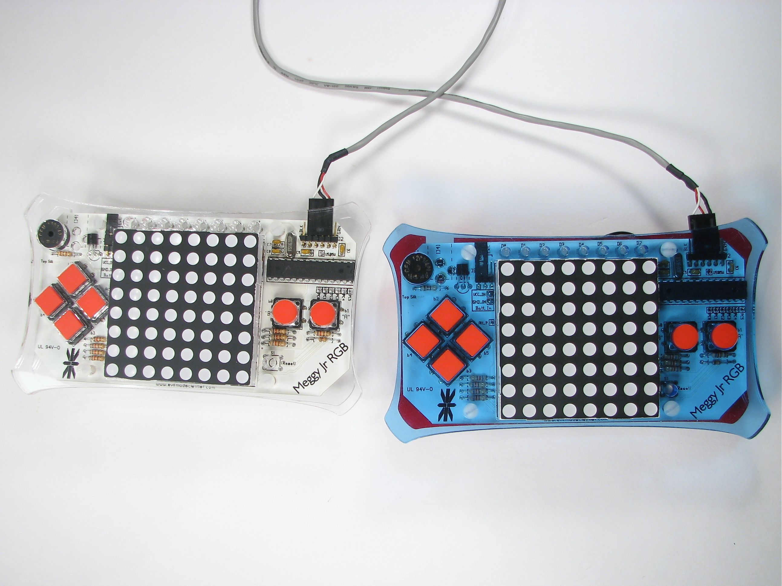
The Meggy Jr RGB has an open serial port that– thus far– hasn’t been used much for gameplay. Something was missing, which turns out to have been this cable that can hook two Meggy Jr’s (Er, Meggies?) together.
Even neater, this cable can be used to provide serial connections between any two of most types of Arduino-compatible devices that normally are programmed through a FTDI USB-TTL cable. This includes not only Meggy Jr RGB, but also the Arduino Pro, the current-revision LilyPad Arduino and the DC Boarduino. (Note: BBB and RBBB users: You can play too, once you wire up CTS# to ground.)
And the cable itself? You can make it yourself– in a couple of minutes– from a standard cable that costs about a buck. :)
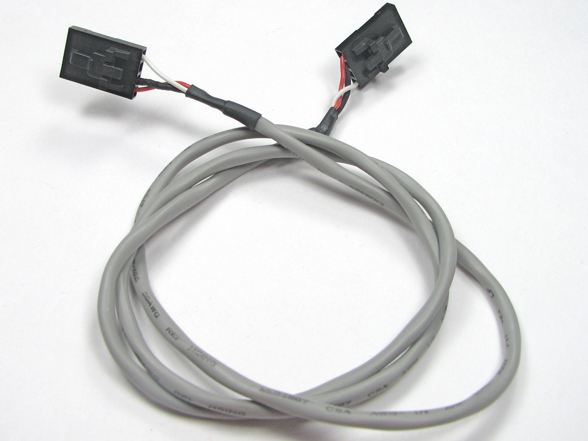
Our starting point is this nice off-the shelf cable. This is the type of cable normally used inside a desktop computer to connect the audio signals from a CD-ROM drive to a motherboard. You can find these listed as just a CD-ROM Motherboard cable or as a MPC2 Audio Cable, and the going rate seems to be about $0.60 and up. Get one that looks like this– two identical four-position connectors on both ends, and at least two feet long. (Also, ask your local case modder. He’s got one.)
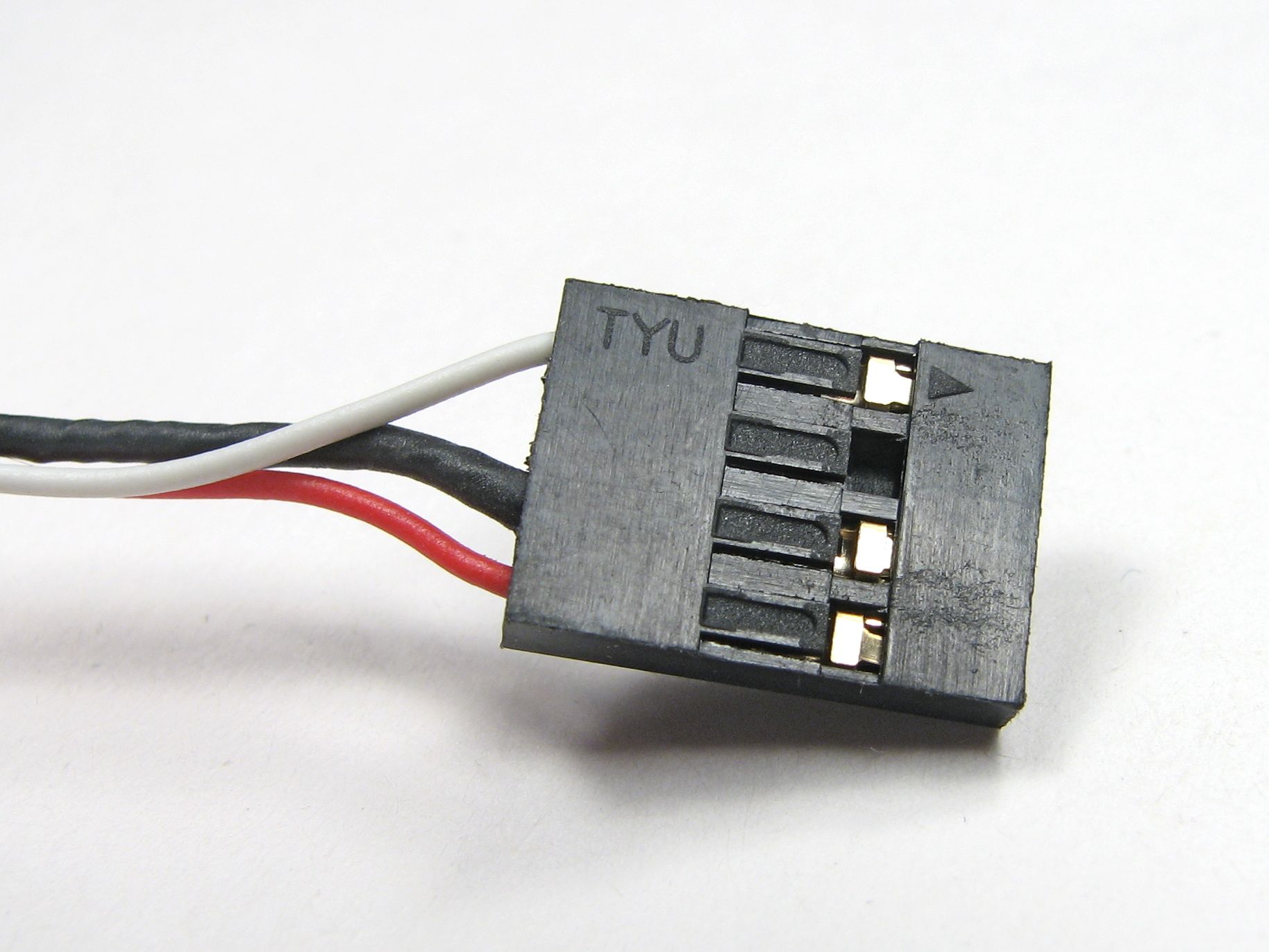
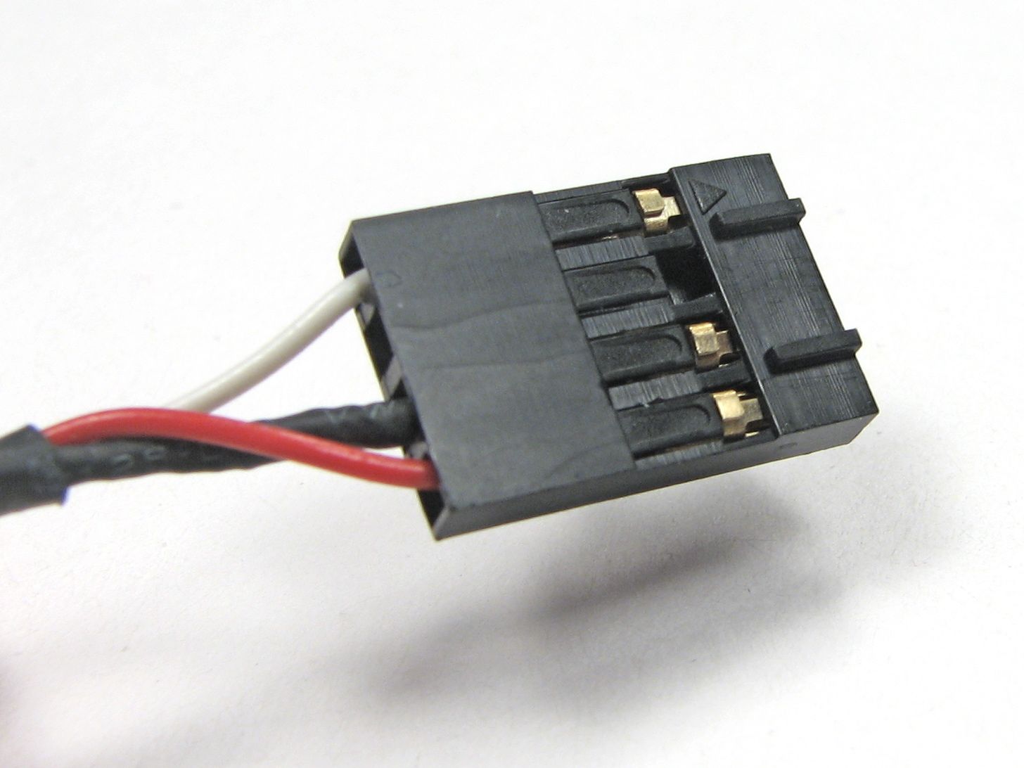
Some cables have ends that look like this: smooth and two dimensional. If so, you can skip ahead a couple of steps.
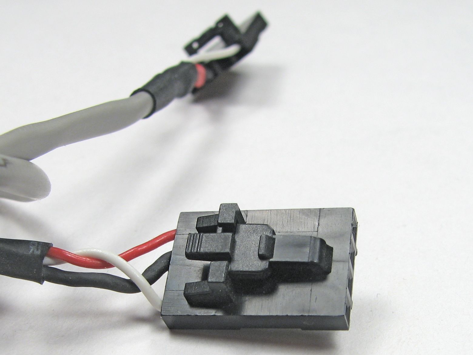
If your cable ends look like this, bumpy, ridged, or tabbed, we’ll first need to remove those tabs.
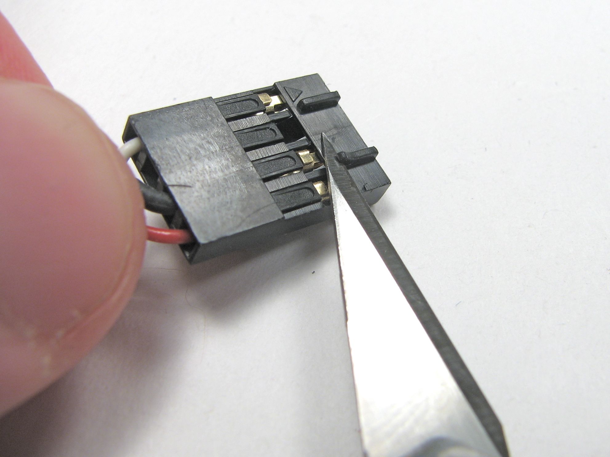
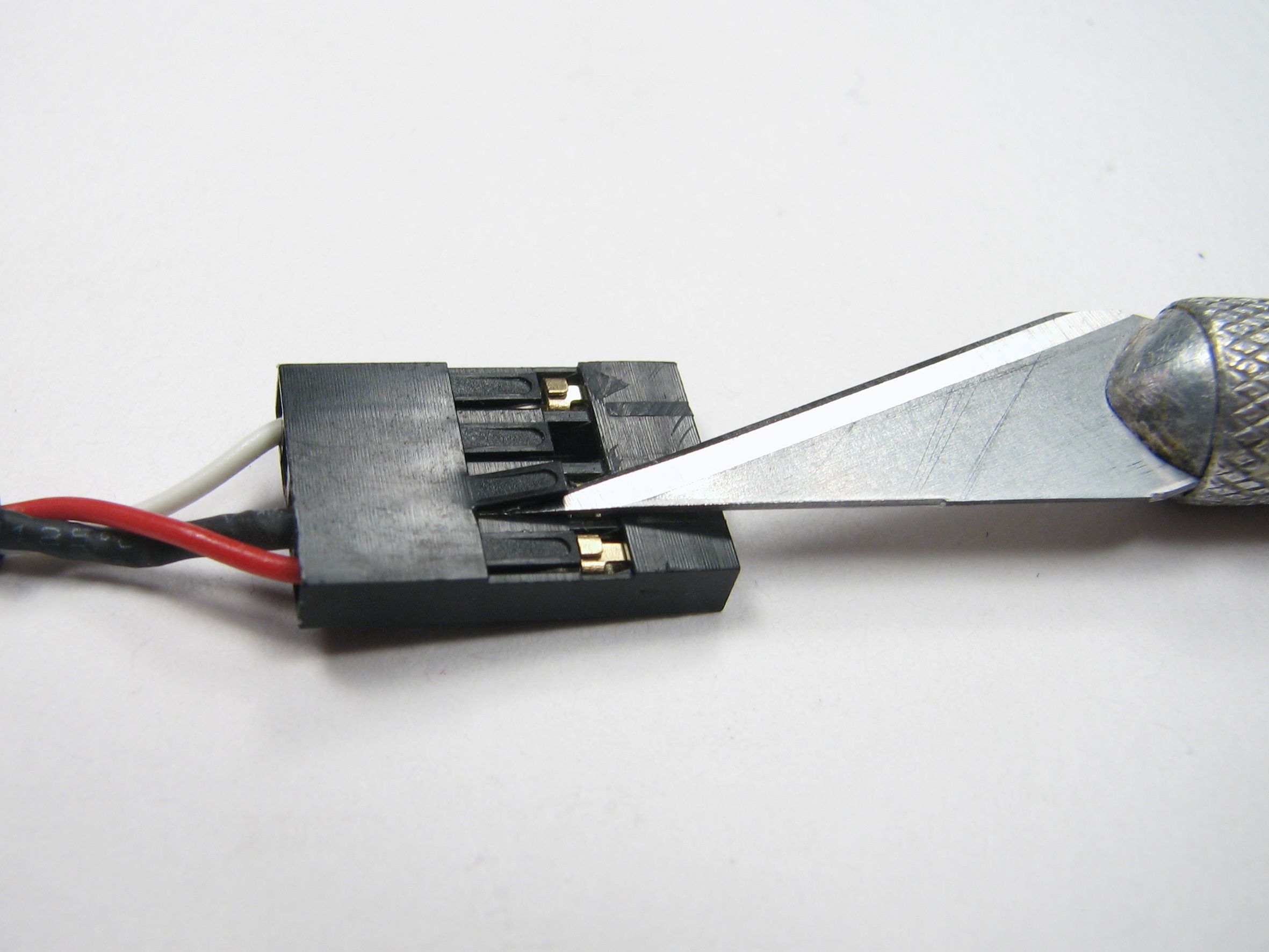
Carefully (i.e., without cutting yourself or poking out an eye), use a sharp hobby knife to cut the tabs off. This works surprisingly well; the type of plastic that is used on these connectors cuts cleanly.
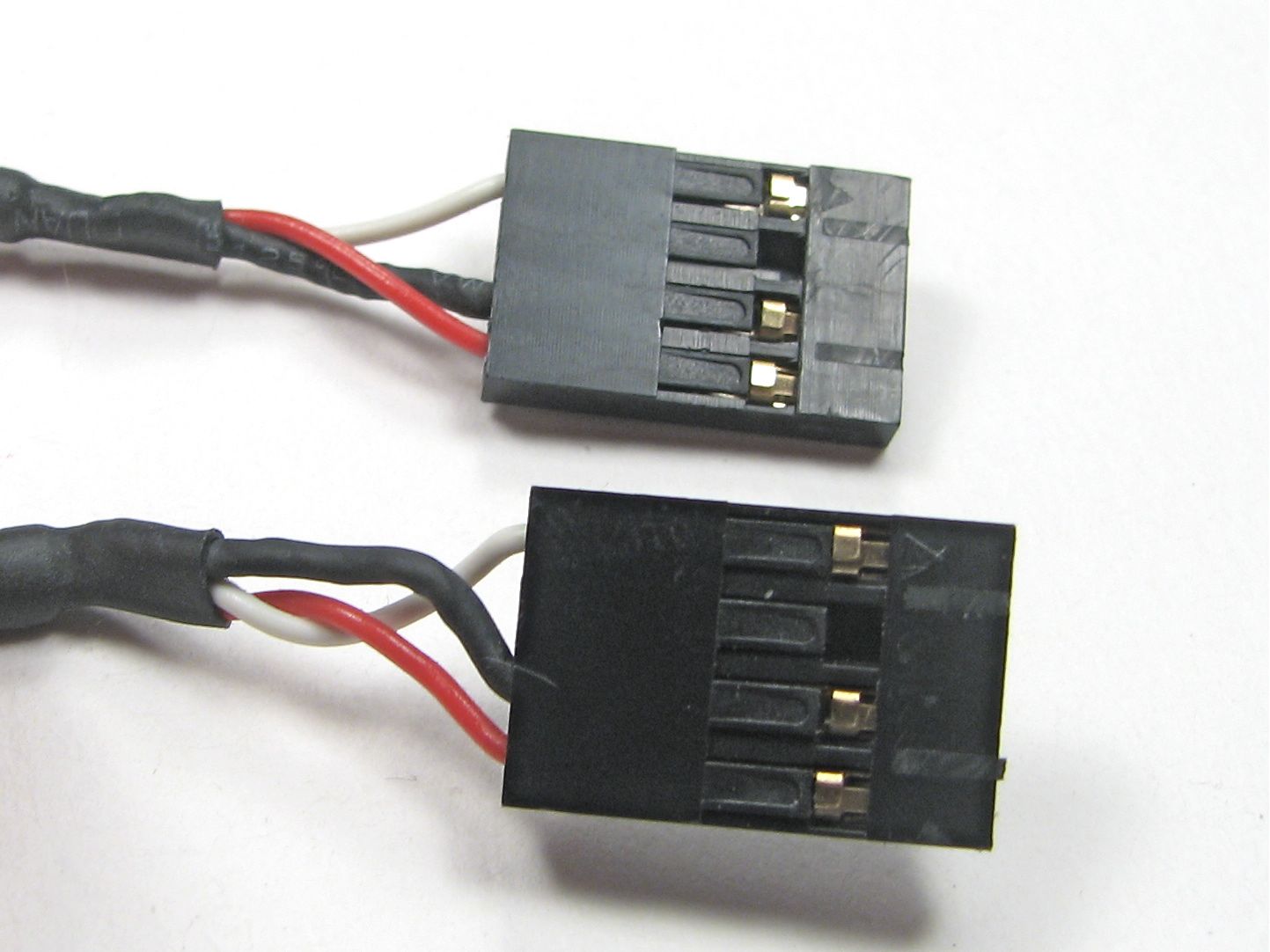
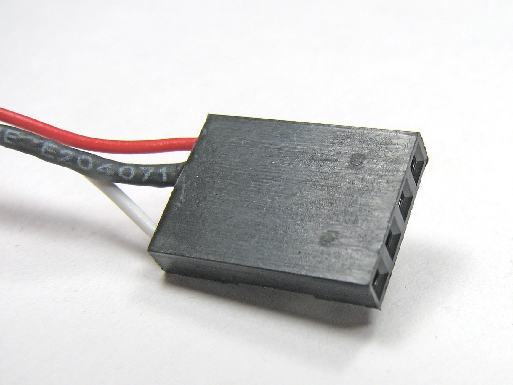
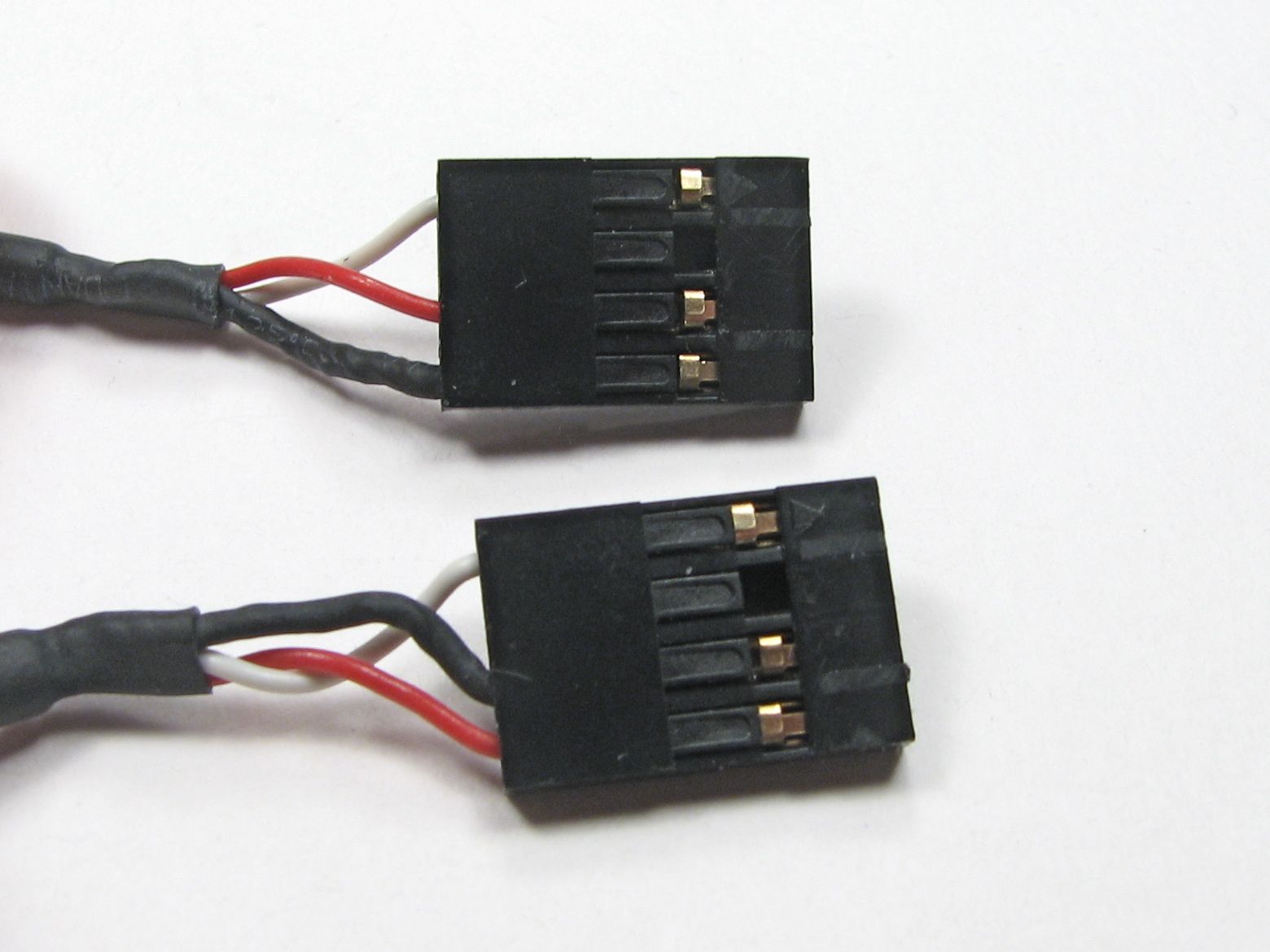
Here is our previously bumpy connector, now neatly trimmed down.
(Photo oops: the lower connector in this photo has a plastic shaving hanging on that makes it look much thicker than it really is!)
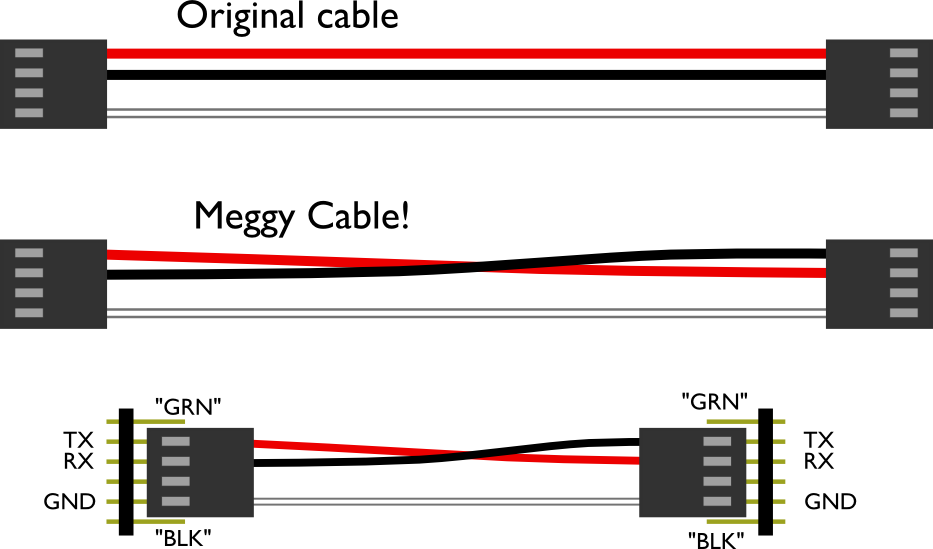
Now that we’ve got our cheap cable trimmed down, let’s look at the mod we’re making. The original cable is a straight passthrough type and has three wires going into the four positions of each cable end. The colors of your wire may vary, and there may even be a fourth wire. (If you do have a fourth wire, you’ll need to remove it.)
What we need to do is to swap the position of the first and second cable positions, red and black here, so that when we hook the cable up to two of our devices, the TX (transmit data) pin of one hooks to the RX (receive data) of the other, so that our devices can start talking to each other.
The labels “GRN” and “BLK” on the bottom drawing correspond to the labels on the Meggy Jr circuit board, for the sake of orientation. For other devices, you may need to look up which pin is which.
To swap the wires, we need to pull out two of the terminals from one end of the cable. The type of terminals can vary a bit, but in all cases there’s a metal or plastic barb to either push down or pull up so that the terminal can slip out.
In this case, the barb is this black plastic tab. We used the end of the hobby knife to gently pull the tab up while we pulled the wire out.
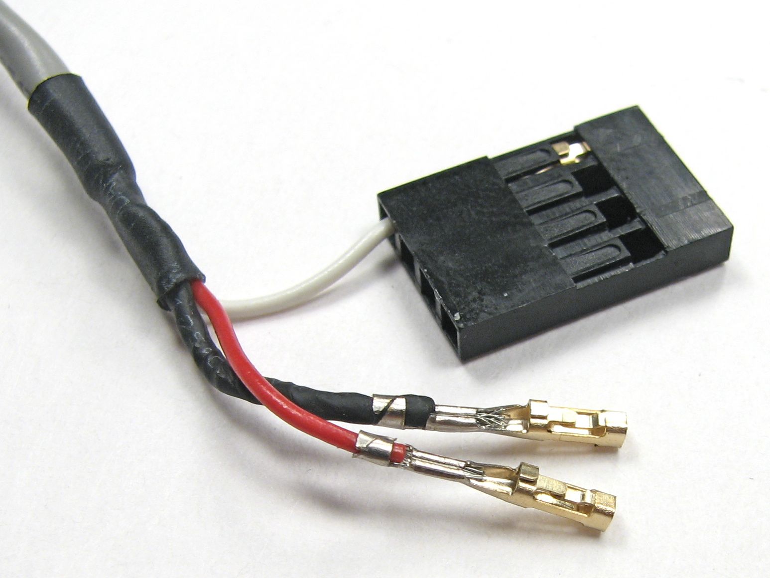
Here’s how it looks when both terminals are pulled out.
Then reverse the wire order, re-insert the ternimals until they snap in place, and the cable is complete!
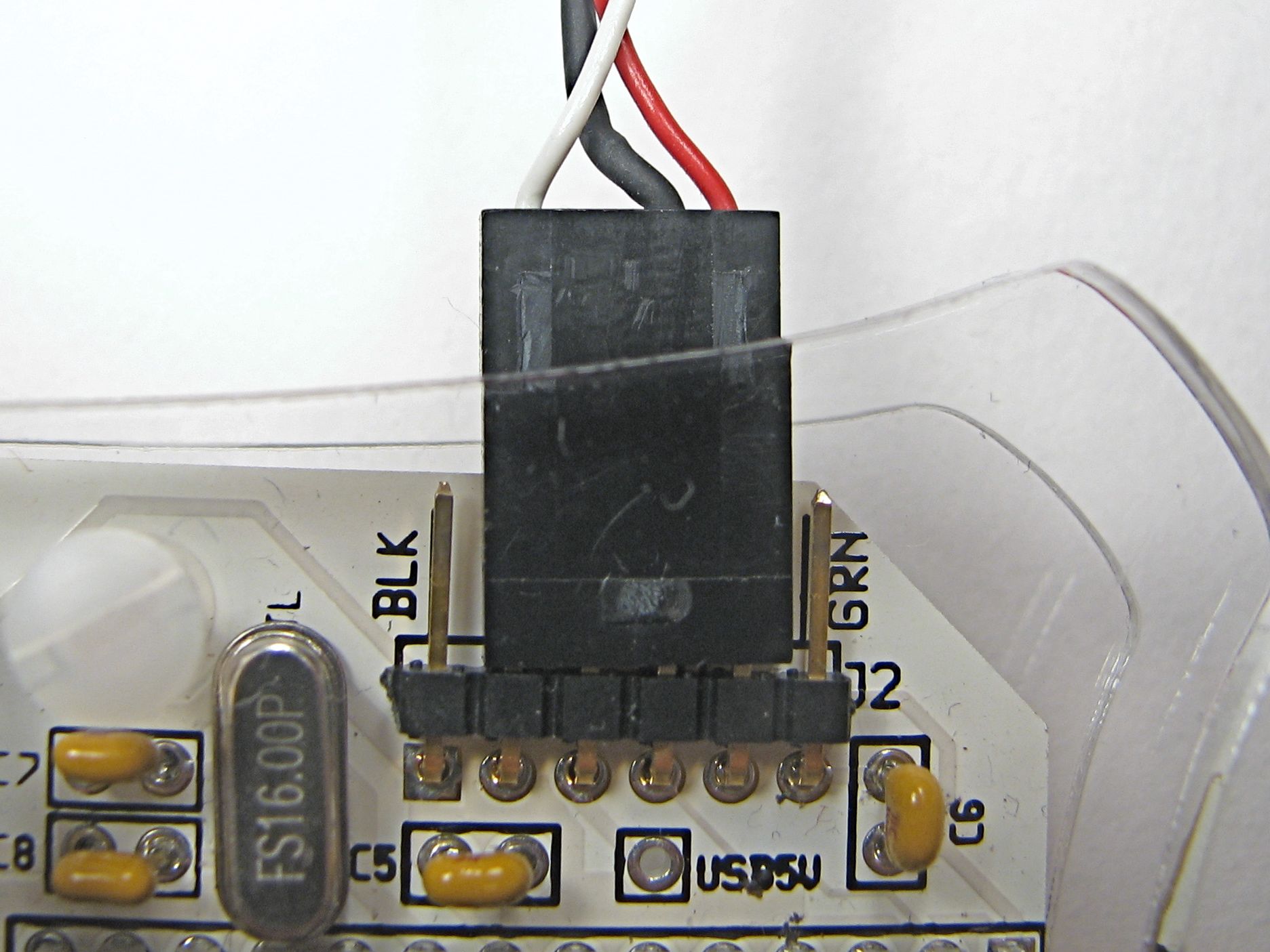
And from there, plug into your devices. The cable fits over the middle fourof the six-pin serial connection. For the Meggy Jr RGB, the two wires (TX/RX) go towards the side marked “GRN” and the single wire goes towards the side marked “BLK.”
Again, on other types of devices, look at the schematic to make sure you understand the orientation.
Game on!
“MeggyChip,” the first dual Meggy Jr RGB game has been posted to our Google Code site, along with some awesome new contributed games we’ve had lately, including Invaders, Gemkeeper, and Meggy Says.
We’ve also added a documentation wiki to our site, where our collection of Meggy Jr projects is documented.

Can’t find it now, but last week I saw a small ‘tag’ game for three players, where each player was represented by an LED and the ‘it’ player would blink. You could use the serial link cable to make a two player ‘tag’ game.
Eh. I’m making here a onecolor-led-version ((pink)) of Meggy, just finished re-desingning circuit board. Left serial port out of it, because it didn’t seem usefull.. *sigh* back to the drawing board it is then.
Meggeese HONK-HONK-HONK
I would be inclined to reorder the pins so that the ground was actually ground, but that just may be my OCD nature ;)
I understand if you just mean *wire color*, but the order of the pins is set by the FTDI cable that all of these boards connect with.
(Also, "ground" is a relatively tricky notion when talking about two isolated devices running on batteries– establishing a common point is very important!)
—
Windell H. Oskay
drwho(at)evilmadscientist.com
http://www.evilmadscientist.com/
It’s not just about color, but the black wire is actually the shielding of the cable.
—
Alex
haha me too, thats exactly what I thought when I saw the pics.
I’m having some trouble with two of the games. The invader sketch is simply too big to upload.
I’ve uploaded the SuperMonkeyKong game, but when I turn my meggy on, it shows the startup screen, but after that, it just lights up AuxLEDs D0, D5, D6 and D7 and emits an annoying buzzing sound, and nothing happens when I press any of the buttons. Can anyone help me?
The forum is probably a better place to discuss things like this, because it’s designed for back-and-forth discussion.
But, you might start by making sure that you’re running Arduino 12 and are using the latest version of the Meggy Jr library (1.31), which these games require.
—
Windell H. Oskay
drwho(at)evilmadscientist.com
http://www.evilmadscientist.com/
Turned out, that I still had the old library installed. I installed the new one, and it works great now. Thanks