


In electronics, it is common to talk about single sided circuit boards. The most common type is a circuit board that only has printed wiring on one side, and components on the other side. There are also surface-mount boards, where all the wiring and components sit on one side. But aren’t all of those reallyjust two-sided circuit boards where you only put components on one of the sides?
Here we present a method of making your own authentic single-sided circuit board.
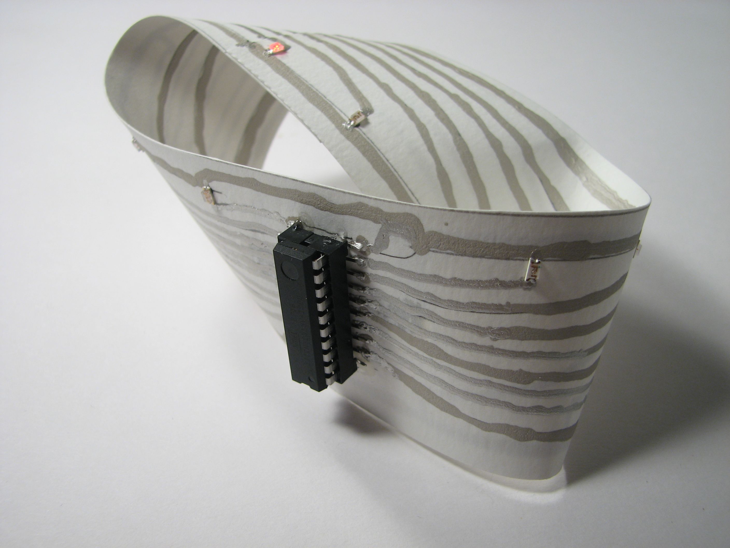
Our solution? A circuit board in the shape of a Mobius strip.
While it is possible to have your own flexible circuit boards commercially fabricated (at a remarkably high cost), we’re executing a much cheaper DIY version here. There are a number of ways that you might go about making your own flexible circuitry– we’re using a paper strip as our substrate and conductive ink for wiring. One of the reasons for this is that our wiring can stay strictly on the one surface of the paper strip, without punching through it. (Maintaining topological integrity is a strong motivation.)
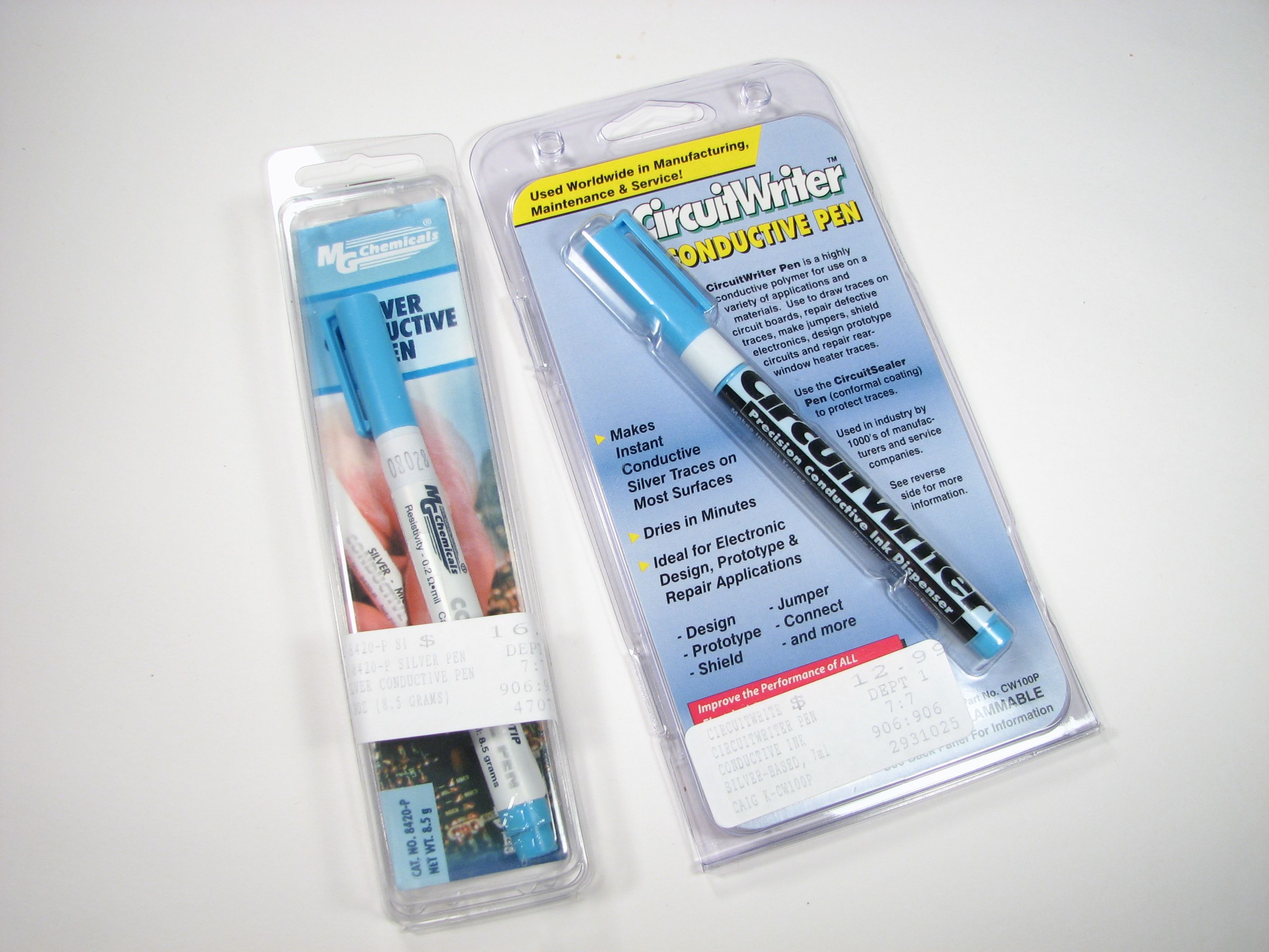
We picked up two different silver-filled “conductive pens” at our local Fry’s Electronics. While the pens look identical, and both make about the same claims, one has 8.5 g of filling and the other has 5 g. One pen produced matte silver traces, the other glorious shiny traces, and at different viscosities. Both types of ink dry impressively quickly and conduct reasonably well for this sort of project. (Expect to lose a few tens of ohms here and there.) One word of warning: This stuff is unforgiving. There is no good way to recover if you should accidentally cross two lines when wiring with conductive ink.
Make sure that your paper is thick enough that the conductive ink will not soak through; we used an 11″ strip of watercolor paper, which worked admirably.
For our circuit, we decided to make an LED chaser that would light up LEDs in sequence along the length of the Mobius strip. To do this we chose a smallish AVR microcontroller, the ATtiny2313, which is a 20-pin device with 17 available output pins. With each output we drive a single red LED, and the whole thing can be powered by a 3V type CR2032 lithium coin cell.
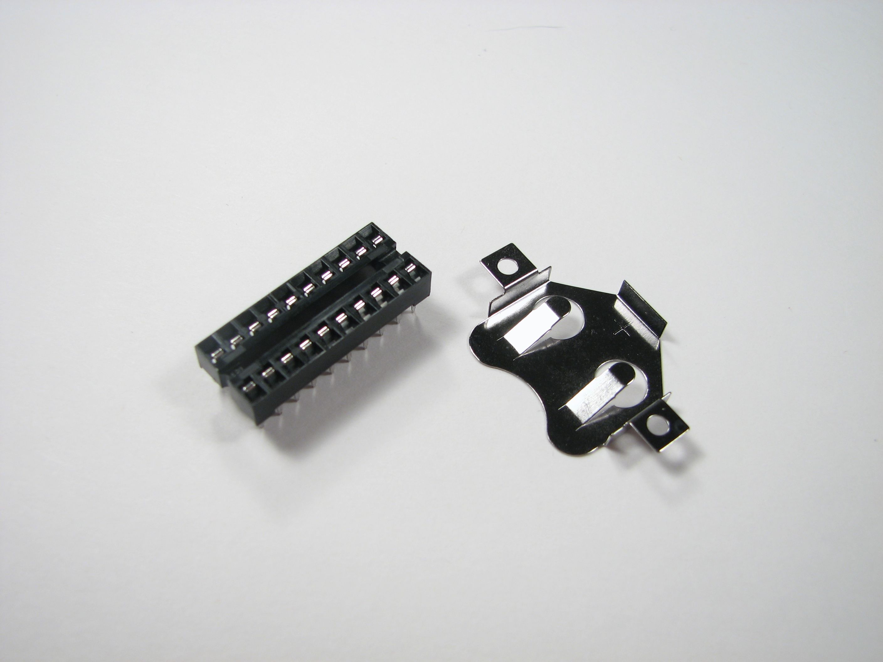
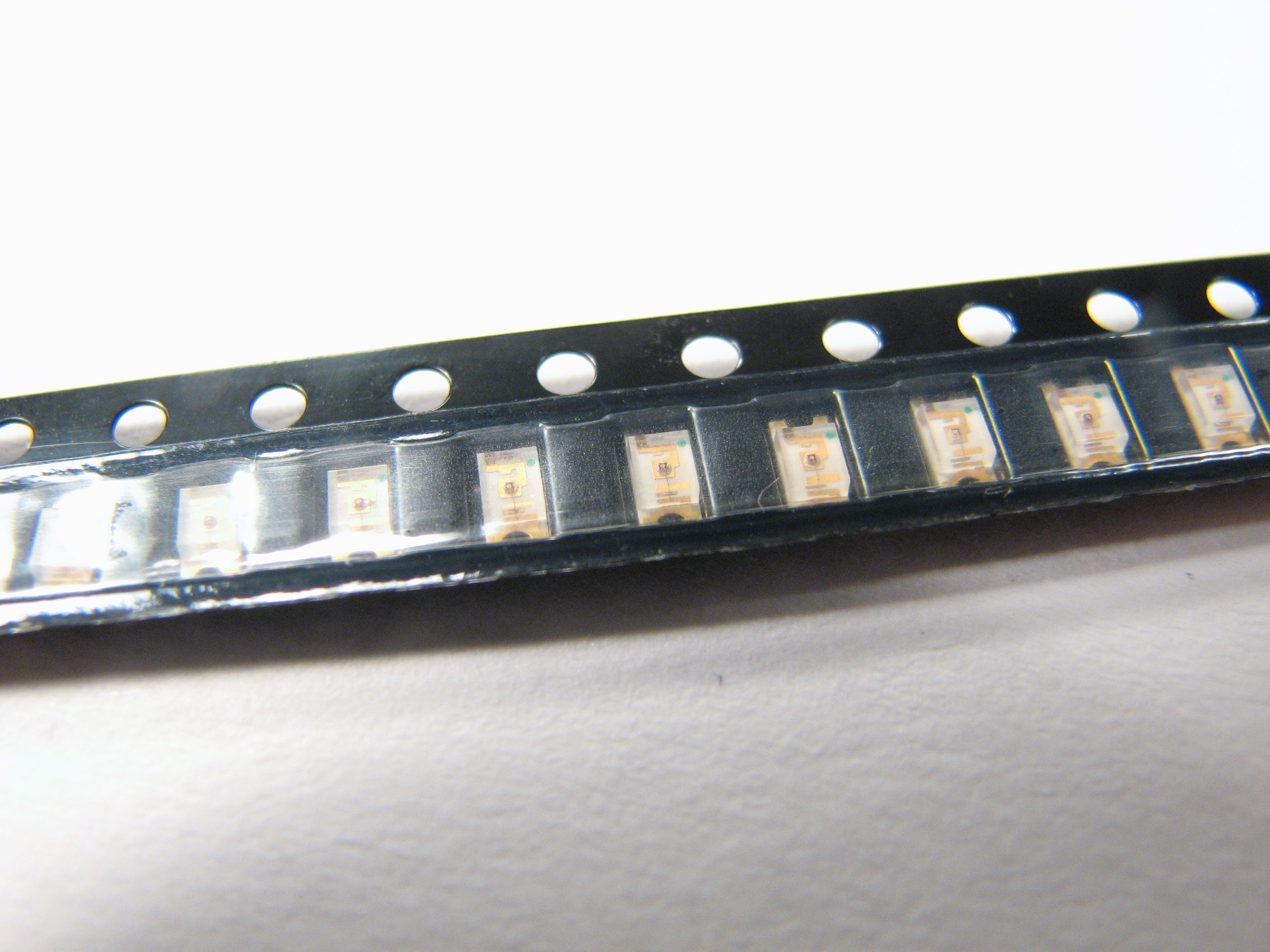
Here are the components that we will need to mount on our board: The socket for the ATtiny2313, a coin cell holder, and small red surface mount LEDs.
We began our layout by placing the socket for the ATtiny2313– with its pins bent out for surface mounting– in the middle of the paper strip, tracing paths outwards from its pins in pencil, and placing the LED locations somewhat uniformly along the length of the strip:
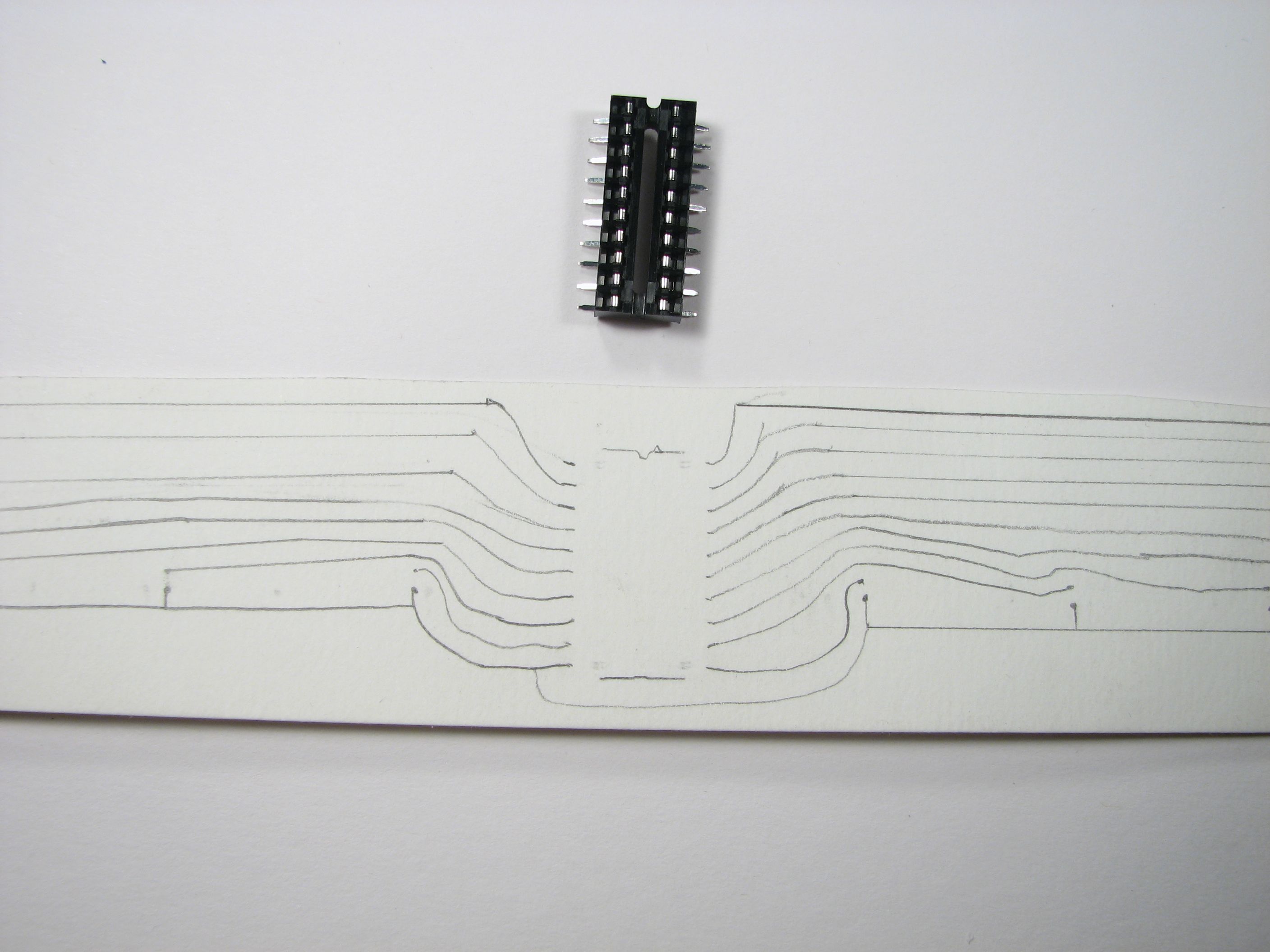
All of our LEDs have their cathodes connected to the ground pin of the microcontroller, pin 10 (on the lower left). Pin 20 (on the upper right) is the +V input, and pin 1 (upper left) is the reset pin that we’ll leave unconnected. All of the other pins lead directly to the nearest, most direct LED.
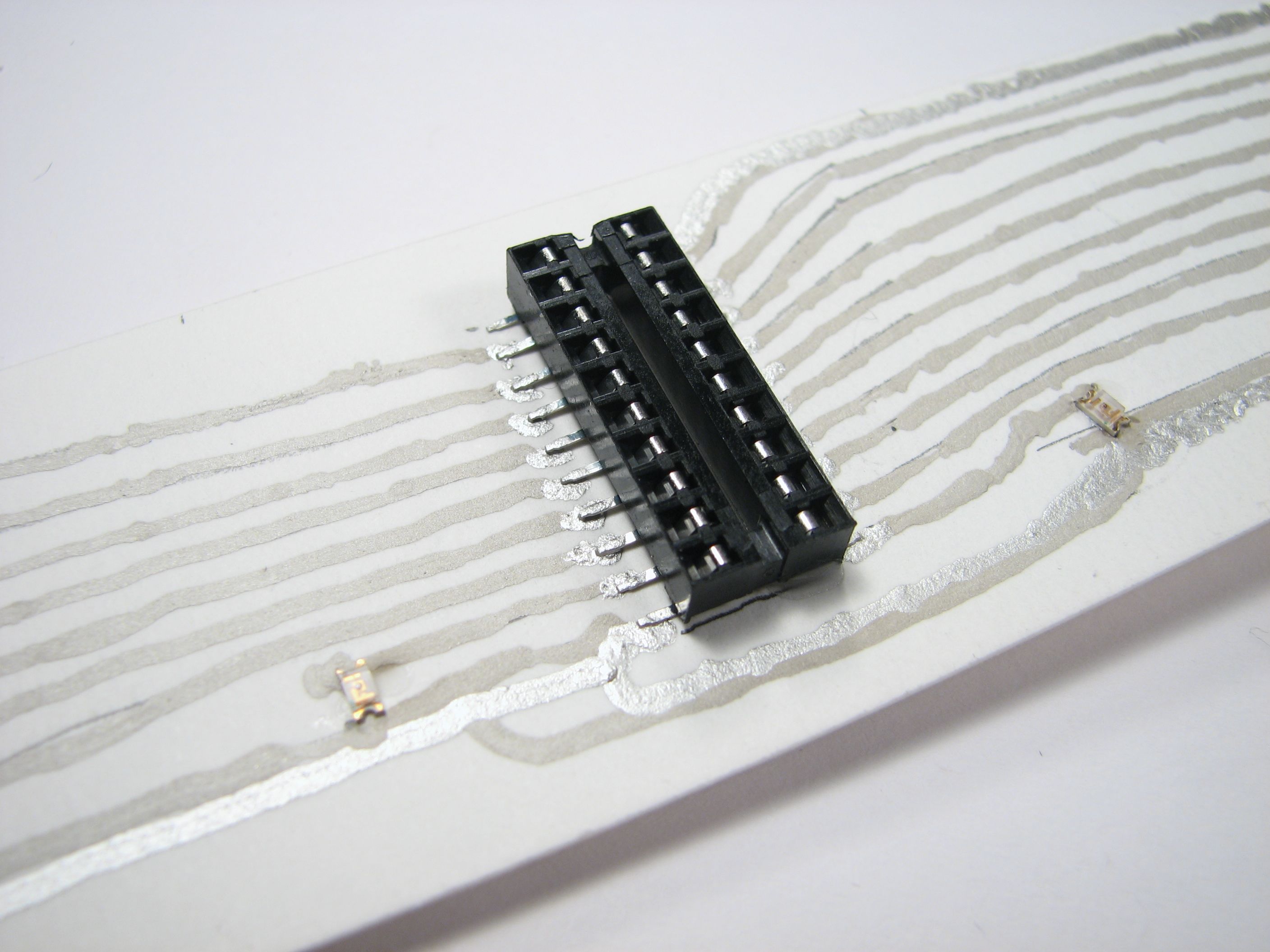
This all looks a lot better once the socket is superglued to the paper and the pencil marks are all written over with the conductive silver ink:
On the reverse side of the strip (which is still two sided at this point!) we install the battery holder, directly across the paper from the microcontroller. This keeps both the chip and the battery well away from the seam where we’ll join the two ends.
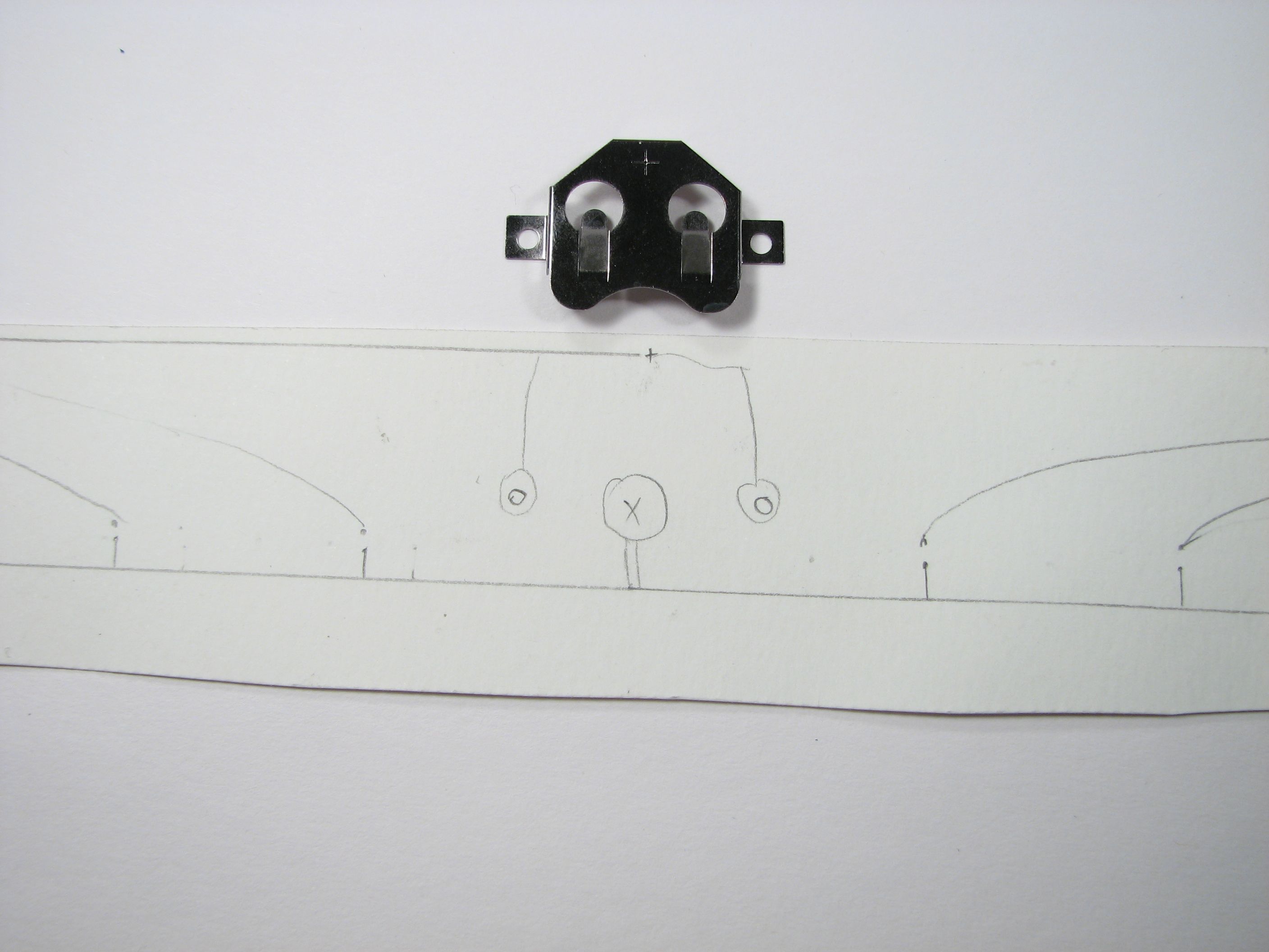
The battery holder is basically a retaining clip that contacts the “+” terminal of the coin cell. It’s up to us to draw a “-” terminal beneath the clip, which we connect to the ground pin of the chip and LEDs.
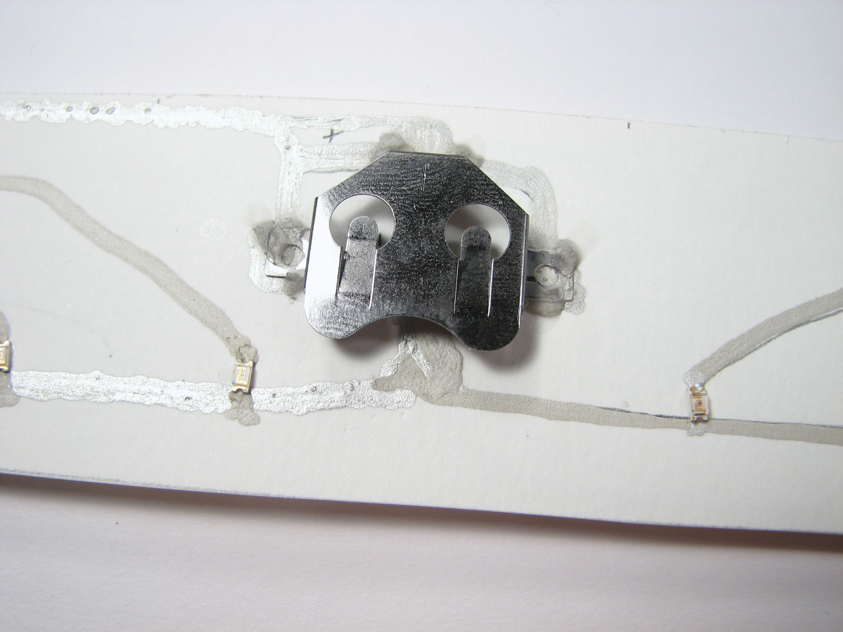
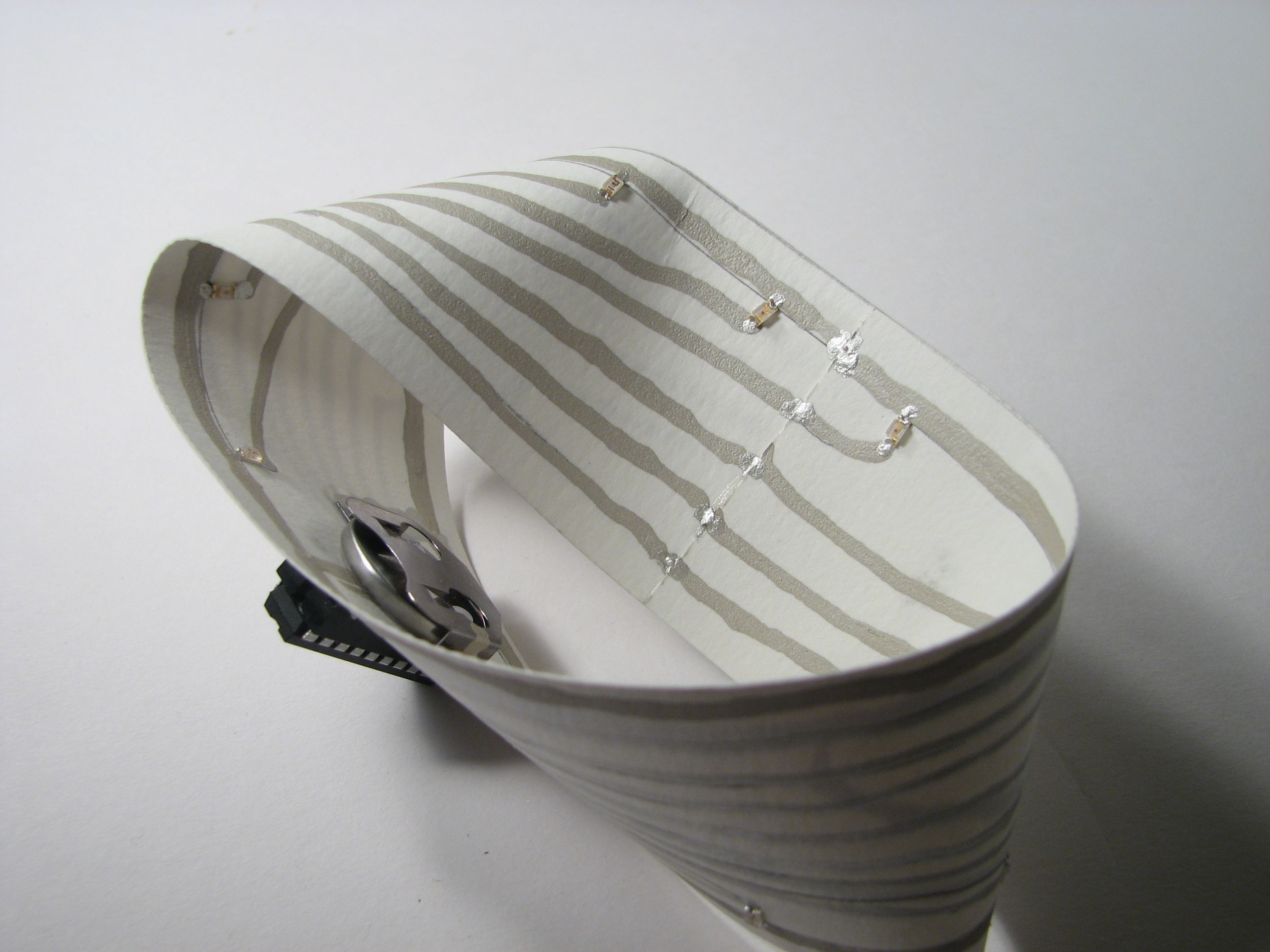
And here’s how it looks once the holder is glued in place, the LEDs are added, and it’s all wired up with conductive ink.
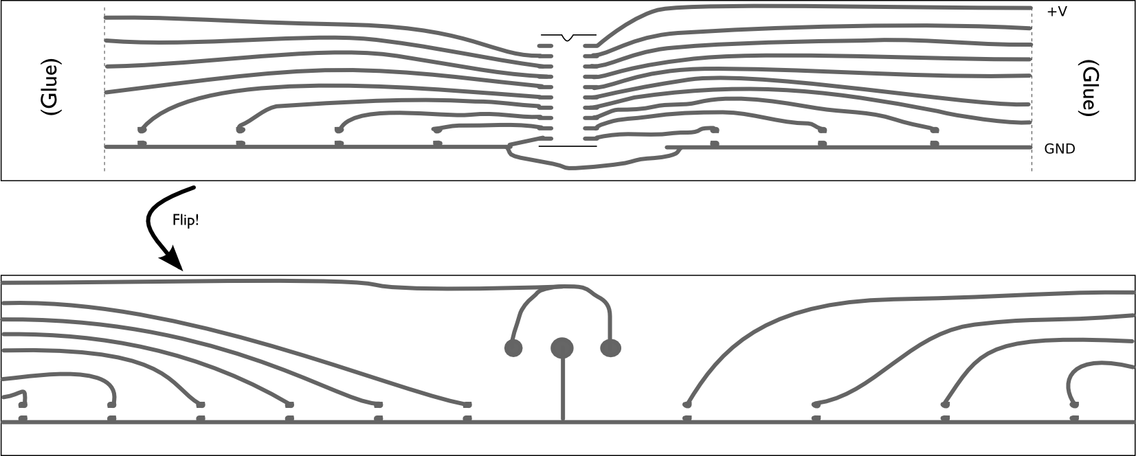
Now, we fit it all together. Our paper strip is 11×1.75″ in size. On the side with the microcontroller, we’ve reserved one inch on each end for glue overlap. On the back side, the full 11 inches is used. Test fitting the strip with a half twist to overlap the two glue flaps lets you see how to connect the lines on the front and back before it’s actually glued together. (Use the pencil to figure out where you’re going to wire before you get out the ink!)
To complete the Mobius strip, attach the two glue flaps together. We used superglue gel, and used clothespins to hold the ends together while it set. Connect the wires across the seam with carefully applied conductive ink.
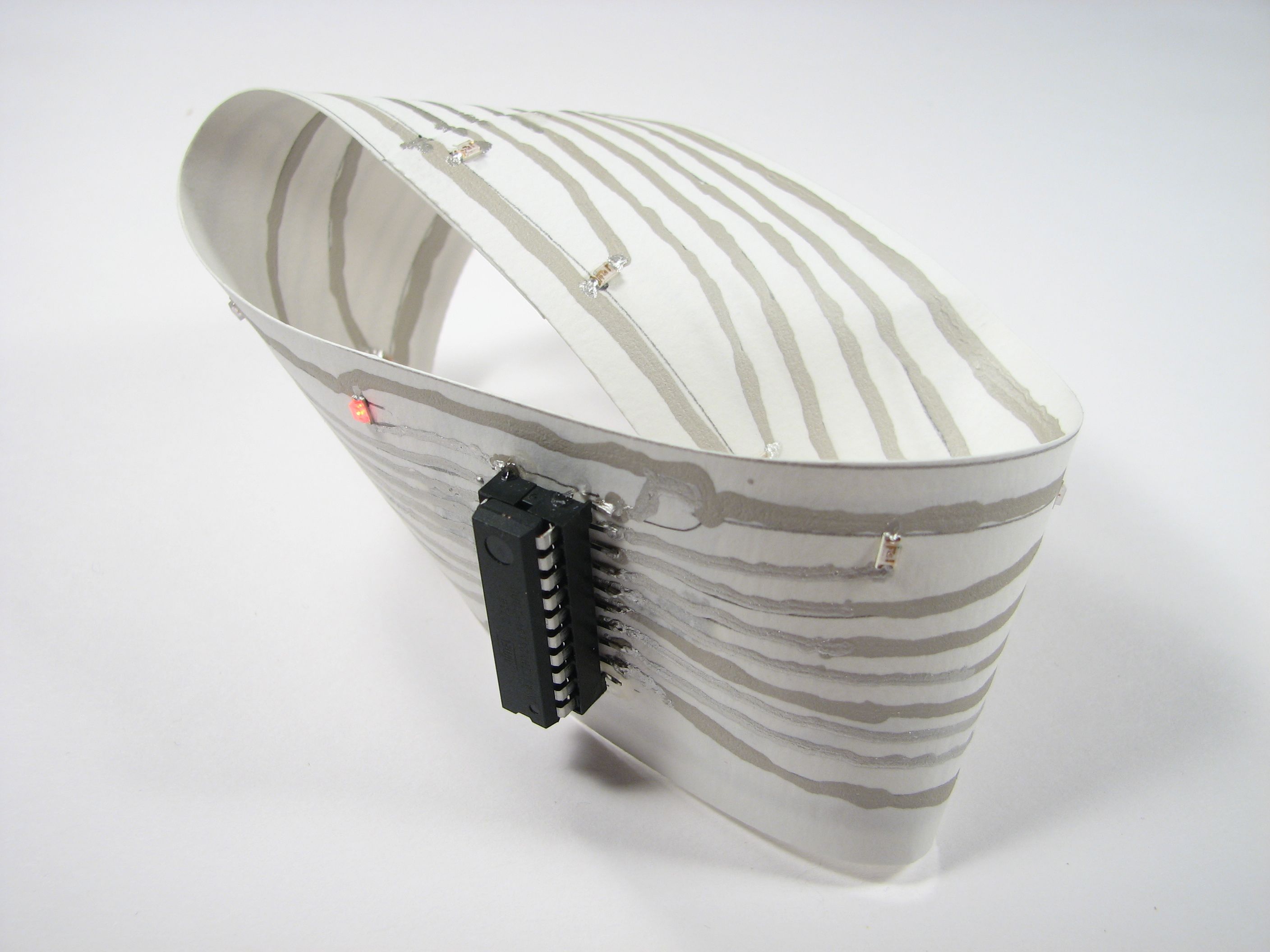
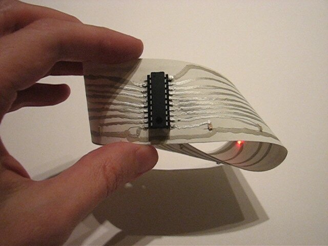
The last step is to program the microcontroller. We wrote a very simple slow “LED chaser” program that lights up the 17 LEDs in sequence, slowly. The firmware for the AVR is being released under the GPL. You can download it here (10 kB .ZIP file) and install it through your favorite interface.
All done and how does it look? Pretty neat!
We also made a short video of the Mobius Circuit which is embedded here. (Please click through to the flickr video page if you can’t see it.)
very nice. It’s impressive how punctual you are with these wonderful projects! If you had to buy only 1 pen would it be the one on the right or the left?
Oh, that’s a tough, tough call. I don’t know if the differences between the pen brands are consistent or not– one or both of the pens could be much older than it’s supposed to be, and I’d have to try a few before making a solid recommendation. Again, both seem about the same electrically. If you needed only one, the one on the left may be the better choice because it gives the shiny shiny output, and was a little easier to control precisely…. and is the larger container. The one on the right, however, was much easier for making big wide traces– it was willing to work at a higher output rate.
—
Windell H. Oskay
drwho(at)evilmadscientist.com
http://www.evilmadscientist.com/
any chance of being able to make pinhole vias?
But then it wouldn’t be single sided any more, would it?
it would still be single-sided if it were still a mobius strip. the vias would be like worm holes.
And why no resistor(s) between the LEDs and Ground? I assume it’s because there’s not enough current in the battery to worry about burning out the resistors?
And what a neat project! It would be fun to see how well you could make this work on other substrates as well, such as wood. Though in that case you could run wires in channels, or something equally silly.
Cheers,
John
>And why no resistor(s) between the LEDs and Ground? I assume it’s because there’s not enough current in the battery to worry about burning out the resistors
That’s right. You can hook one of these batteries straight to a red LED and not worry about it blowing out. Also, there *is* a resistor– each of those long traces (battery + to microcontroller, microcontroller to LED, LED to battery -) has substantial resistance, of order 10 ohms. What’s really amazing is that there’s enough voltage headroom for the microcontroller to run there as well.
—
Windell H. Oskay
drwho(at)evilmadscientist.com
http://www.evilmadscientist.com/
dear sir,
i think your post is a bit one sided.
< grin >
the poster got me to scroll down because he said it lights up!!! lights up good!
I wonder if there’s an autorouter made that could handle routing a circuit like this.
I think vias, in a mobius pcb, are actually called jumpers…
Now do the same on Klein bottle :)
I’ve bought a couple of the conductive pens on the right. They also produced matte traces and worked at a high output rate.