


Forum Replies Created
-
AuthorPosts
-
Windell OskayKeymaster
OK, great thanks– looks like your computer can see the EBB, but not communicate with it. (Edit: Obviously you were seeing it in a different way earlier– the ACM* ports are how we try to address it.)
And, checking here– yikes— we have the same situation. It looks like something in the latest round of Ubuntu updates is interfering with our serial communication. I am not yet sure what the issue is, but we *will* make this our top priority to sort out, and I’ll post back here with a solution as soon as possible.Yes, you can use 12 V directly, with up to 1.25 A per phase (assuming that your power supply is juicy enough). You can read more about the EiBotBoard and its capabilities here: http://www.schmalzhaus.com/EBB/Windell OskayKeymaster>Lbuntu “/dev/serial/by-id# ls usb-SchmalzHaus_EiBotBoard-if00”
I’m not sure that I follow. First, is “Lbuntu” the same as Lubuntu, or is this a different distribution?Second, please try the following command, and let me know what output you get:#ls /dev/ttyACM*> Opened Inkscape – same problem – servo appears to be ‘locked’ and the steppers are a bit stiffer – Probably still need more power to the steppers. How many volts and what size Amp wise will the bot board Handle?Have you been able to communicate with the EBB at any point through Inkscape? It is not necessary (or even, a particularly good idea) to adjust the motor current setting until after you have established communication. And, we recommend a 9V/1.5 A power supply.Windell OskayKeymasterFirst, which Linux distribution/version are you using? We developed the Eggbot under Ubuntu, and we’ve had scattered reports of success with other distributions as well. (And, one person reported having trouble with Gentoo last year, but we’ve been unable to reproduce the setup locally.)
Second, check to see if the Eggbot has shown up as a USB-ACM interface on your computer. The EiBotBoard (EBB) normally shows up on linux machines as /dev/ttyACM* (e.g., /dev/ttyACM0), so look for it there.
If it is present, try again from Inkscape, at least twice in a row, to see if you can get a connection.
You may also want to consider unplugging it and plugging it back in, trying a different USB cable (if you have one handy), or if you are using an extra long/thin USB cable or hub, going back to the original cable for testing.
We have seen some suggestion that USB devices may not register on linux until after a restart, but I’d try that only as a last resort.
Please let us know how it goes!
Windell OskayKeymasterGood news/bad news: It looks like this is a known bug in Inkscape, with a fix committed. However, the fix is committed for version 0.49, which is not yet released. Darn.
Windell OskayKeymasterOn second thought, looking at your picture, it looks like something has gone wrong here. The right portion of the uppermost straight line has disappeared, and it seems to do this on my computer as well. Yikes.
Windell OskayKeymasterI’ve just tested this again, with the same example, and it seems to work fine. You do still have to click on each of those horizontal line segments, and delete them individually.
If it’s not working, perhaps the paths were not combined successfully. If those paths have been combined, then you should be able to click on the combined path (once) and then be able to click and drag it. Also, when it is selected, the status bar at the bottom of the screen should read “Path (84 nodes) in Layer 1.”Windell OskayKeymaster>I tried your first method, and it works great for the spiral lines, but not so great for the straight lines. I’ll work on it a bit and see if I can figure out how to do that.
This technique *should* work equally well for straight lines, and I’ve confirmed (with the example file above) that it does, provided (1) that the oval actually overlaps the straight lines and (2) that you combine (Path>Combine) all of the paths that you wish to cut before selecting them for the Cut Path operation. You can also use multiple cut path operations, with multiple copies of the oval, to cut the additional paths if you do not wish to combine them.Windell OskayKeymasterHi William,
You’ve brought up a number of issues here, which I’ll try to address one by one.First, as the Eggbot is fundamentally a pen plotter, it strives to accurately plot the paths in a drawing. It relies on humans to change the pens and figure out which layer should be drawn in which color. This can lead to some non-WYSIWYG behavior, in the sense that we don’t normally *use* white ink with the Eggbot, but it’s easy to draw white ink on the screen.
Clipping and masking in Inkscape– and as far as I understand in Illustrator and Corel Draw as well –does not modify the underlying vector drawing, but rather changes which part of the vector drawing is rendered to a bitmap display device: either your screen or an exported bitmap image. That is to say, no vector drawing of the actual clipped shape is ever created, which is why there is no straightforward way for the Eggbot to draw that clipped shape.For reference, here are a couple of tutorials on clipping and masking in Inkscape and Illustrator:http://inkscapetutorials.wordpress.com/2011/02/22/inkscape-faq-how-do-i-crop-in-inkscape/
Now, I understand that you see serious shortfalls in Inkscape, but so far as I can see, this is fundamentally correct behavior, and in fact the same behavior as you would see in Illustrator or Corel Draw. It just turns out that this method isn’t really helpful for making Eggbot artwork. In general, I personally prefer Inkscape, and have on more than one occasion transferred files so that I could edit them in Inkscape before returning them to Illustrator or Corel. So, I suspect that this is mostly a matter of personal preference.To actually create a vector shape that represents your “clipped” vector, there are a few different approaches, depending on what you want to do. In Illustrator, there are the “pathfinder” operations. In Inkscape, there are the “boolean” path operations that perform a similar set of actions.In any case, there are actually tools in Inkscape that can cut a complex open-ended path with another: the “Cut Path,” “Difference” and “Division” operations in the Path menu. Here is an example of how to use it for the “traditional1” pattern. This is actually a rather unusual example, because we’re trying to cut an open, arbitrary path (rather than a closed object– the more common case) with a second path.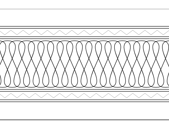 Here’s the starting figure.
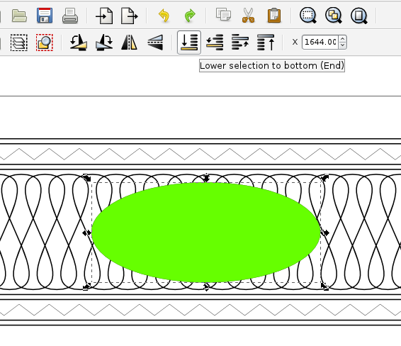 * Draw an oval that we will punch out.* Duplicate the oval (Edit>Duplicate) to make a second copy, because the oval will be consumed by the Cut Path operation.* Click on the oval and lower it to the bottom of the drawing. (Object>Lower to bottom)
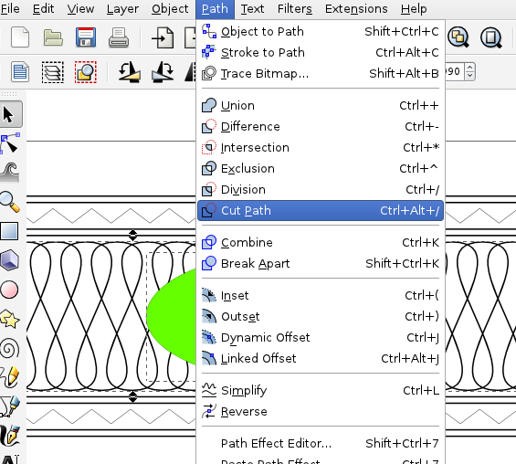 * Select the background path (that which you wish to cut) and the oval. (Shift-click to select more than one item.)* Perform the cut path operation: Path menu> Cut Path
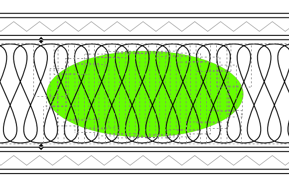 The Cut Path operation consumes the selected oval, and cuts the background path everywhere that it intersected the oval. The oval still visible is the one that we created and placed there by using Duplicate and Lower to bottom.
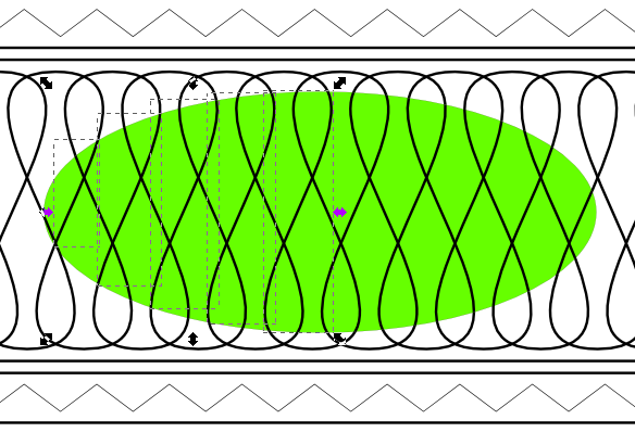 Select the path bits inside the green oval and delete them. You can select more than one at a time (using Shift-click) to delete a bunch at once.
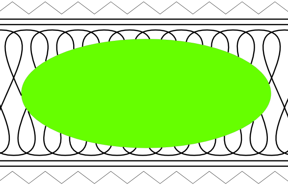 All of the inner bits have been removed.
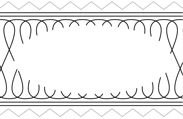 Select and delete the oval. Done!
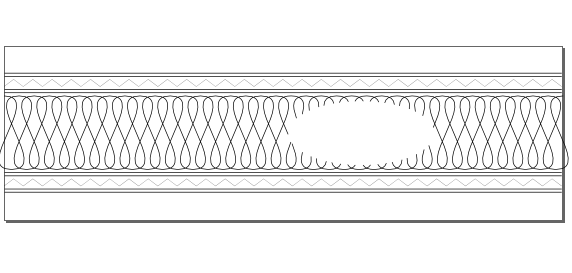 Also, here is an easier, but “less exact” method. This method will result in tracing all of the background “propeller” pattern twice, *but* it will print surprisingly quickly because there are fewer pen lifts:
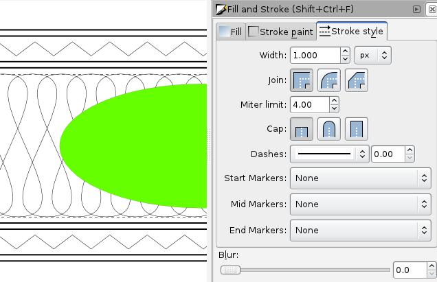 Begin with the same “traditional1” example pattern, and an oval on top that we wish to punch out.Optional step, for skinnier lines: Select the background “propeller” pattern, and change its line width to 0.001″
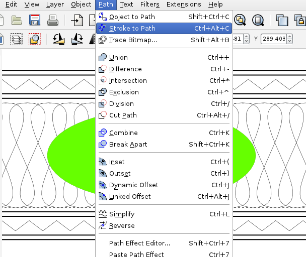 With the background pattern still selected, choose from the menu “Path>Stroke to path.” This changes that object from being a single line (defined by its stroke only) to being a closed, filled path that is the width of the original line.
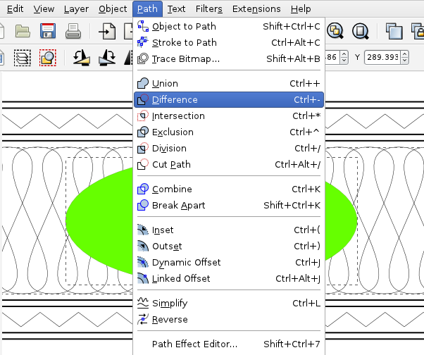 Now that we have two filled objects to work with, we can use the more common boolean tools. Select both the oval and the background pattern, and select from the Path menu> Difference.
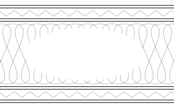 And we’re done.Windell OskayKeymaster
Have you been unable to do this with the boolean operations or the cut path operation? I’d suggest that you actually try to modify the path in the way that you want, rather than just try to hide part of it.
Windell OskayKeymasterGreat, glad to hear it!
Windell OskayKeymasterHave you tried adjusting the motor current yet?>It acts like they want to move, but more or less have the same pulse that the pen lift motor does.
Again, can you please describe what kind of a pulse this is?Windell OskayKeymasterHi fire-497,
When you enable the motors, do the steppers seem to actually energize– that is, do they resist motion? Or, is there actually no apparent change? Do the steppers seem to move at all when you try to plot?And, can you describe what you mean by the “pulses?”Windell OskayKeymasterI’m not sure that I understand the situation fully; perhaps you can clarify a few things:
1. Columns 0-16 are dim, and 17-25 are bright, even after swapping U4/U5. Correct?2. Do you have some other LEDs that are not lighting correctly?3. Have you finished installing the LEDs yet?Windell OskayKeymasterI’m not aware of any standard cable like that, although we have used one or the other end of one of the 6-pin rainbow cables for similar applications now and then: http://shop.evilmadscientist.com/productsmenu/partsmenu/586
These cables are pretty easy to cut up and modify, as we demonstrated with the GPS project, for example:February 28, 2013 at 5:45 pm in reply to: Alpha Clock Five and serial in Python from a Raspberry Pi #21210Windell OskayKeymasterOkay, so there must be something still screwy about the Pi’s USB driver. Good to know for future reference, at least.
-
AuthorPosts