


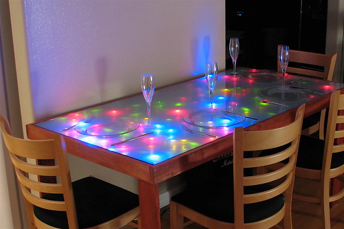
Today we’re releasing the circuit diagram for the Interactive LED Dining Table (aka our kitchen table).
We’re releasing this as a free (and fully unsupported) project design, so… “Have fun, kids!”

The circuit consists of 16 individual analog computer nodes that are connected together in a 1-D chain.

Each node has this circuit diagram, driven by a quad op-amp chip, taking input from a photodiode, and storing the result in an analog variable (integrator). You can also download a PDF of this circuit diagram.
See also our original article, and download the PDF booklet about building this monster of a circuit here (5.5 MB PDF).

Wow that’s wonderful! Thanks so much for sharing your design. Happy Birthday indeed :-)
Fantastic! Thanks, EMSL! Now I finally know how the table works – it’s been bugging me for a while.
I should remind everyone that their kits are still priced very competitively; it would cost around 80-90 per board if one were to have their own design made by a board house, which is about what these kits cost – and the kits include all the other parts, too!
This thing was just a bloody nightmare to make– something like a full week of soldering every evening. You can do it *once,* and then you would want to do what we did: go to the circuit board panels that cost more but go together quickly.
By the way– our kits start at only about $55/panel. :)
—
Windell H. Oskay
drwho(at)evilmadscientist.com
http://www.evilmadscientist.com/
Is this the schematic for the old design (obfuscated blinking pattern) or the new design (trail of lights pattern)?
This is the only dining table circuit that we ever made; it’s what we brought to the first Maker Faire (San Mateo 2006).
—
Windell H. Oskay
drwho(at)evilmadscientist.com
http://www.evilmadscientist.com/
LOL! I love the circuit diagram. It has –class– :D
thank you so much for this gift. I’ve been fascinated with your design since I first saw it at the make blog. cheers!
Thanks and Happy Birthday! I was hoping that you might do this to celebrate!
Are they actually 22M ohm resistors ? Or should they be 2M2 ?
Just what it says: 22M.
—
Windell H. Oskay
drwho(at)evilmadscientist.com
http://www.evilmadscientist.com/
Have you an indication about the power comsumption of your invention?
The LED’s are not lit at the same time, I am guessing.
It should be pretty obvious from the circuit diagram.
—
Windell H. Oskay
drwho(at)evilmadscientist.com
http://www.evilmadscientist.com/
Excellent work!
So if the overall table has a 1D network topology, why the two neighbour outputs and inputs? Could you connect each node to more than one neighbour?
In principle, you can connect to additional nodes. In practice, it tends to be less "interesting" if you do so, which is why we kept the 1-D topology.
—
Windell H. Oskay
drwho(at)evilmadscientist.com
http://www.evilmadscientist.com/
Excellent, thanks.
Thanks
Thanks a bunch! Really appreciate ya’ll doing this. Looking forward to tinkering with this circuit.
I’m intrigued by this circuit, and would love to see it in action. Does a video of it operating exist?
Because it uses photodiodes, how does it work in low/no light? Does it shimmer slightly like the other tables you’ve made?
Cheers,
Steve
You might want to follow the first link up above to read more about the table and its behavior. It does not shimmer, or settle down to "zero" when unstimulated– it’s designed to slowly change between different stable states. It does not do as well in the dark as our coffee table design; it can begin to oscillate on its own.
—
Windell H. Oskay
drwho(at)evilmadscientist.com
http://www.evilmadscientist.com/
My apologies: I found the video. Thanks :)
Any recommendations on what kind of photodiode works best? Wavelength? Current ratings?
We used type SFH203.
—
Windell H. Oskay
drwho(at)evilmadscientist.com
http://www.evilmadscientist.com/
This Circuit does not want to work! Both strings of led’s stay on, and the output of the opamp integrator circuit is not oscillating. I have created the circuit 4 times, all with different components from different suppliers with the same result. Also I have tried using 2 different circuit simulator programs. I am not normally one to ask for help, but this is really bugging me! What could be causing this result? All components are the same as listed, I have used poly caps and green caps, +9,-9 volts, and +12,-12 volts, what voltage did you supply to the opamps?
Do you need to have anything attached to the Neighbor in and out if it is a single node?
>Both strings of led’s stay on, and the output of the opamp integrator circuit is not oscillating.
The integrator circuit is *NOT* supposed to oscillate. (If it does, something is very wrong.)
>I have used poly caps and green caps,
I don’t know what "green" caps are– you should use the poly caps.
>+9,-9 volts, and +12,-12 volts, what voltage did you supply to the opamps?
The circuit requires +/- 15 V for the LEDs and op-amps. This is supposed to be simple; there aren’t extra power supplies at other voltages. If your power supply can’t reach +/- 15 V, then your LEDs will probably not turn off all the way. Also, you should used mixed LEDs of different colors. If you use a solid color (e.g., all red) things may turn out quite differently.
>Do you need to have anything attached to the Neighbor in and out if it is a single node?
Nope. You can just leave those resistors off altogether.
—
Windell H. Oskay
drwho(at)evilmadscientist.com
http://www.evilmadscientist.com/
I’m sorry, the way I understood the circuit to work, was the integrator output varied the voltage from +15 to -15 volts when the Transmittance amp picked up a change in ambient light through the photodiode. This in turn changed the string of LED’s that were on. If you could you please explain to me what the transmittance amp does so I can test for the problem.
I tried my circuit with fewer LED’s so that I could achieve the same brightness off of +12, -12 voltage supply. The opamps and the LED’s were powered from the same rails, and ground was assumed to be the 0 volt point in between the two 12 volt batteries I have in series. So I am not too sure what the problem is.
The green caps, are also known as Metallised Polyester Capacitors, sorry for the confusion. The LED’s I’m using were all red, but did not vary in output at all. It was as I did not even connect the output of the integrator to the center of the two series clusters of LED’s
>If you could you please explain to me what the transmittance amp does so I can test for the problem.
Don’t think I’ve ever heard of a “transmittance amp.” The output of the first op-amp (a transimpedance stage) should be directly proportional to the amount of light hitting it. If that’s not the case, start debugging there.
>I tried my circuit with fewer LED’s so that I could achieve the same brightness off of +12, -12 voltage supply.
Since you’re using red LEDs, you’ll need to use the same number of (or maybe more) LEDs at +/- 12 V or you may burn them up.
>The opamps and the LED’s were powered from the same rails, and ground was assumed to be the 0 volt point in between the two 12 volt batteries I have in series.
You’ll need strong batteries– this is a power-hungry circuit, especially when you overdrive the LEDs.
>So I am not too sure what the problem is.
When you are making a circuit of an unfamiliar type, it might be best to start out making it according to the original design first, before you start to make a bunch of small changes– those can make it harder to find the issues.
>The green caps, are also known as Metallised Polyester Capacitors, sorry for the confusion.
Good choice.
>The LED’s I’m using were all red
That is a significant design change… not to be taken for granted.
—
Windell H. Oskay
drwho(at)evilmadscientist.com
http://www.evilmadscientist.com/
im panning to do this for my electronic class project and ive bieng wondering where the power for the circuit comes in as i can see 15v for the leds
and what about the grounds are they conected to the power source and if yes to how mush.
razielnakourou@hotmail.com
thank you
This is not a beginner project– if you don’t already have the basic idea from the circuit diagram, it’s likely that you’ll end up pretty frustrated at some point when trying to build it.
That said, there are some hints about the voltages in the earlier comments.
—
Windell H. Oskay
drwho(at)evilmadscientist.com
http://www.evilmadscientist.com/
Hello,
Thanks for sharing this project, Windell..
I made this circuit on a breadboard.
But leds are not oscillating. when lihgt is on, one group leds are on(other group off), when the light is off, last group leds are off, and the other group are on…
It works same as that. Ýt doens’t reduce and increase led’s light slowly.. Just "ON-OFF"
I wait your helps,
Best regards,
securityman2000( a t )hotmil.com
It’s not supposed to oscillate. It should be able to settle down to different states beyond just on or off– it should have intermediate tones as well, although it may not be easy to get it to settle there if you only have a couple of nodes.
—
Windell H. Oskay
drwho(at)evilmadscientist.com
http://www.evilmadscientist.com/
Yes, I made a single node. Do you think that is the problem?
It’s not obviously a "problem," it’s quite possibly working how it’s supposed to for a single node. Build up four nodes on a breadboard– that’s a good way to see how it behaves.
—
Windell H. Oskay
drwho(at)evilmadscientist.com
http://www.evilmadscientist.com/
My questions are this:
What circuit did you use to power the circuit?
What is the minimum number of nodes that can be connected together. meaning if i build one to test will it work?
Will the circuit work with 1 or 2 LEDS?
I typed my post quickly so ill clarify some things now.
how did you power all the circuits. did you buy some power supply or build one, if so what would be the best way to go about powering the nodes.
how many nodes must be connected together to get results?
and lastly, what is the minimum number of LED’s that you can use on each node, i would prefer to use less then the circuit diagram says which from what i see is 28 LED’s on each node, i would prefer to use around 4 LED’s on each node, is this possible?
As it says in the diagram, this uses +/- 15 V supplies. Modifications are certainly possible, but you’ll need to work through the diagram and understand how the circuit works a bit before you start changing things.
—
Windell H. Oskay
drwho(at)evilmadscientist.com
http://www.evilmadscientist.com/
I would like to know the rough power consumption of each block, 4 blocks, 8 blocks? I found a dual power supply located at http://www.marchandelec.com/ps10.html . I am familiar with the parts in use but would you recommend 1 or 2 of these PSUs or something like the ones you offer on your site?
Thanks for your reply.
B.
I’m hoping somebody is still following this…
Looking at the photographs of your node circuits I see you use metal film resistors for the 22Mohm and 1Mohm resistors, are the metal film ones necessary or can I use carbon film ones?
Either will work.
Windell H. Oskay
drwho(at)evilmadscientist.com
http://www.evilmadscientist.com/
Hi, Just wondering if this circuit has been modified on the latest version of the table boards. The circuit board dimensions you use, won’t fit neatly into the table I wish to build in. I want to use all white led’s like the newer design.
Cheers
Richard
No, this is a different circuit. The "dining table" circuit is an independent design that we haven’t used in an other contexts. It can be modified to work with white LEDs by reducing the number of LEDs on each side, maybe to 8 or 9 per side (down from 14). Let us know if you do it– it might be cool to see.
Windell H. Oskay
drwho(at)evilmadscientist.com
http://www.evilmadscientist.com/
I have a question. In each side there are 14 LEDs (red, blue. yellow, green). Led’s are operated at 2-4 volts at 20mA. Lets take an average for all 14 diodes that operate at 3 volts, so 14 * 3 = 42 volts and supply voltage is 15 volts on one side. Could you explain how the scheme operates please.
Interesting circuit – how critical is the supply voltage? I’ve built it on a breadboard with a supply I had lying about, which outputs 38V.
I’m getting some response when I move my hand over the photodiode but not much…
Absolutely critical. Use a regulated supply.
Windell H. Oskay
drwho(at)evilmadscientist.com
http://www.evilmadscientist.com/