


We use a lot of our ATmegaXX8 “business card” breakout boards for the ATmega168 microcontroller. We also still wire up a lot of minimal target boards to use the ATtiny2313 microcontroller, so here’s the missing piece: A simple breakout board for the ATtiny2313.
The ATtiny2313 is a popular AVR microcontroller; it’s the one found in the MiniPOV, LED Mini Menorahand many other neat little kits.
Like the original card, our design goals for this project were (1) to make a printed circuit board version of the minimalist target board for the microcontroller, encompassing a place for the chip and a connection to the 6-pin ISP header, (2) to make a minimal and inexpensive circuit board platform that you could use to deploy a single AVR somewhere with without much fuss, (3) to encompass the capacity of a breakout board, giving extra holes to tap into each pin of the AVR and provide labels for every pin, (4) to fit in some small amount of flexible prototyping space, (5) to make it all fit into a neat business-card form factor, and (6) to release it as an open-source project.
The Design
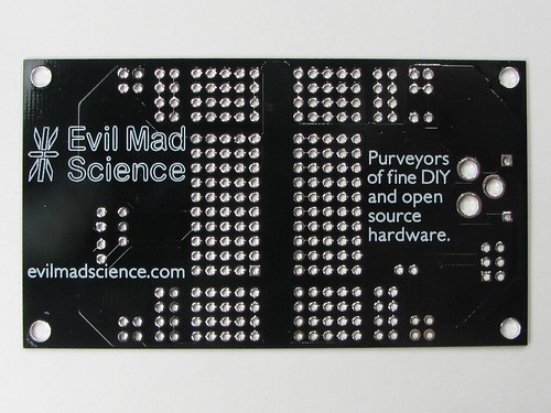
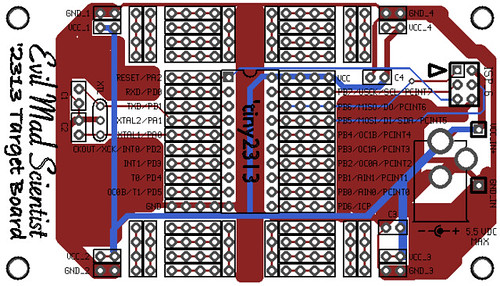
The circuit board is 2″ x 3.5″ (Standard business card size of course). The bottom side silkscreen on this has our store information; if you’re making your own version of this you can obviously replace that with your own contact information.
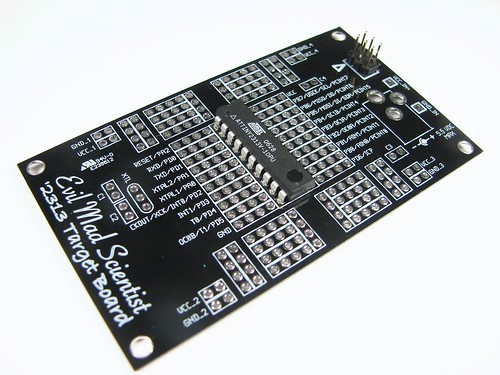
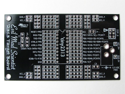
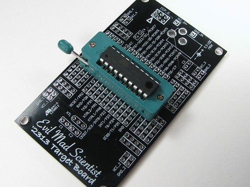
On the top side of the board, dominating the playing field, is the place for the microcontroller, which can sit in a standard DIP socket. We’ve also made the holes big enough to accommodate a ZIF socket for easy programming.
All 20 pins of the microcontroller are labeled with their main functions. Besides the pins that actually connect to the ATtiny2313, there are four access holes connected to every pin of the microcontroller. In the upper left, there are input connections for power (typically 3-5 V) and ground, which are routed to a couple of other locations on the board. In the upper right is a place for the 6-pin ISP header with pin 1 marked. In the lower right is a place to add an optional crystal oscillator with its two capacitors, or a 3-pin ceramic resonator.
Finally, mounting holes are provided in each corner for 6-32 size screws, located with centers 1/8″ x 1/8″ from each corner.
Using the board
Since this is effectively an implementation of the minimalist target board, you don’t need much to run one of these. Ideally, the board, plus a chip, plus the 6-pin ISP header and a programming interface (at least once). To run on its own it will need and external power source as well, and AVRs like this can run (depending on load) from a 3V lithium coin cell or from a more powerful source. We usually run ours on external battery boxes with switches, either with two or three AA cells. This board has a location for a power jack onboard, that takes a center-positive DC voltage up to 5 V.
Under the hood
This is a very straightforward breakout board, so there shouldn’t be any surprises in the layout. We’ve made the ground traces nice and fat, and routed power and ground connections to several useful places on the board.
To get started working with this design on your own, we have a single ZIP file, available for download here, (492 kB .ZIP file) which contains the full schematic diagram (PDF format), a PDF of the PCB layout showing the individual circuit board layers broken out individually with crop marks– making this layout a cinch even for home-etched circuit boards, and the original PCB layout file. (The circuit board was designed in gEDA PCB— free, open-source printed circuit board software.) We are releasing the design for this board under open source licenses and under a creative commons license as well.
Or, take the easy way out and get a kit here. :)
Want to talk about it? That’s what the forums are for.
Got projects based on this board to show off? We’d love to see your pictures in the Evil Mad Science Auxiliary.
Update, 7/2009
Version 1.1 of this project is now available. Please see here for the details.

Looks great. I’ll be ordering a couple. I may be showing off my inexperience here, but is there a reason there are two smaller prototyping areas on each side of the chip instead of one larger area that can hold a 14 or 16 pin DIP?
—
Art Dahm • My Peggy 2.0 Web Page • http://www.mindlessdiversions.com/peggy2/
Among other differences, we put four holes next to each pin (instead of three), and tried to fit *all* of the pin labels on the board, which meant that it was not very practical to orient the chip sideways like we did on the other board.
So it became a surprisingly difficult layout, and we ended up orienting the chip 90 degrees from how we did on the other board… and centering the chip on the board seemed like a good idea.
—
Windell H. Oskay
drwho(at)evilmadscientist.com
http://www.evilmadscientist.com/
Totaly L33t
now i need to find one for the 8pin attiny13 and im goldeen
The ATtiny13 is mostly obsolete; it’s been replaced by the ATtiny13A.
—
Windell H. Oskay
drwho(at)evilmadscientist.com
http://www.evilmadscientist.com/
Can you explain the purpose and recommended values of C3 and C4 to us novices? Thanks!
—
Art Dahm • My Peggy 2.0 Web Page • http://www.mindlessdiversions.com/peggy2/
ICs can be sensitive to noisy power, which can happen for several reasons… If you have power issues, adding one (or both) capacitors can help. The capacitors across Vcc and Ground basically "store up" some of the voltage when it’s high, and release it back into the circuit when it’s low, smoothing out the fluctuations.
—
I think I am, therefore I am… I think
Put four holes next to each pin (instead of three), and tried to fit *all* of the pin labels on the board, which meant that it was not very practical to orient the chip sideways like we did on the other board.So it became a surprisingly difficult layout, and we ended up orienting the chip 90 degrees from how we did on the other board… and centering the chip on…
This is good stuff – I was just planning a project based on ATtinys. As far as getting boards manufactered goes (never attempted before), should this be straightforward?
None of the fab houses I could find specifically mentioned geda PCB but a) I may have misunderstood what I was reading, and b) a look through the manual finds "RS-274-X (Gerber) output". I presume that Gerber is ok? (realise there might be some vendor-vendor varations)
Thanks
We send gerber files to the fab house.
This is a bit like exchanging any other kind of documents. You want to send them the finished, printed thing. Sending gerber files is like sending PDF as opposed to MS word documents. It’s much more likely to come out correctly in the end, without "missing fonts" (er, footprints) and so forth.
—
Windell H. Oskay
drwho(at)evilmadscientist.com
http://www.evilmadscientist.com/
I just turned one of these into a dual 8-pin/20-pin programming cradle by adding a jumper in one of the prototype areas to connect/disconnect ground from pin 4. Remove the jumper to program a 2123, add the jumper to program a 13.