


This is a quick how-to guide on making ultra-simple development boards for programming AVR microcontrollers. Most recent-vintage AVRs can be programmed through an ISP (in-system programmer) connection; all that is really needed is a place for the chip to sit and a way to connect to the programmer.
That’s where these minimalist AVR “target boards” come in. These little boards cost only about $2 and take only a few minutes to make.
It turns out that I build a lot of these because asking “how do you make a circuit to program the AVR?” is really the same as asking how you can program an AVR that is in a circuit. And, we might as well start with a simple circuit.
There are two basic types of microcontroller programmer that you can imagine: one that has a socket for your chip, and one that hooks up to your circuit where your chip is installed. We’re interested in the latter, the set of so-called in-system programmers, sometimes called in-circuit programmers. You can also get programmers with dedicated sockets, of course, but they are typically more expensive and are not fundamentally “better.” With an in-system programmer, not only can you program microcontrollers that are in larger circuits, but you can also easily make programmer target boards with sockets, giving you the benefits of a programmer with a socket.
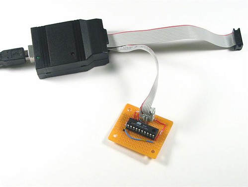
The de facto standard USB in-system AVR programmer is the Atmel AVRISP mkII, part number ATAVRISP2-ND from Digi-Key, for $36. I actually wrote a bit about using this programmer last year. It’s a good very-few-frills programmer and it works quite well. It has a hard plastic shell with a USB “B” connector on one end and a cable ending in a 6-pin ISP connector on the other end. (If you take the case off of the AVRISP mkII, the circuit board has a place for you to add a 10-pin ISP cable as well, but this is an unpublicized feature.)
One drawback to this programmer is that it requires external power to be applied to the target board in order to operate. That’s kind of silly, because the programmer draws the power that it needs to operate from USB, but does not pass that through to power the microcontroller during programming. Ideally, the programmer should have a switch, so that you can either use the programmer to power your target board or not.
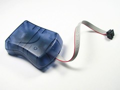
The new USBtinyISP AVR Programmer from Adafruit industries (Reviewed here) is probably a better choice for most applications. It comes as an easy kit for $18.00 $22.00 and it includes both 6-pin and 10-pin interfaces. The killer feature versus the AVRISP mkII is that it lets you use the USB power to directly power your target board. Well, that and that it comes with both6-pin and 10-pin ISP cable connections.
One other neat option (for some of you): You can use Arduino as an AVR-ISP programmer.
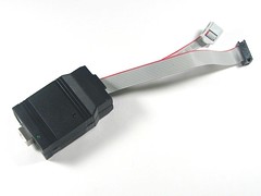
For folks that don’t want USB, there is no shortage of serial and parallel ISP programmers. Most of them use the 10-pin interface. Adafruit has one of each serial and parallel. You can also get them from other sources (e.g., SparkFun), but usually at a higher cost. And, if you do have a parallel port, let’s not forget that you can almost whip one up out of thin
air.
Anyway, back to the target boards. Previously we’ve mainly used “real” development boards that include power supplies, communications, and a crystal oscillator.
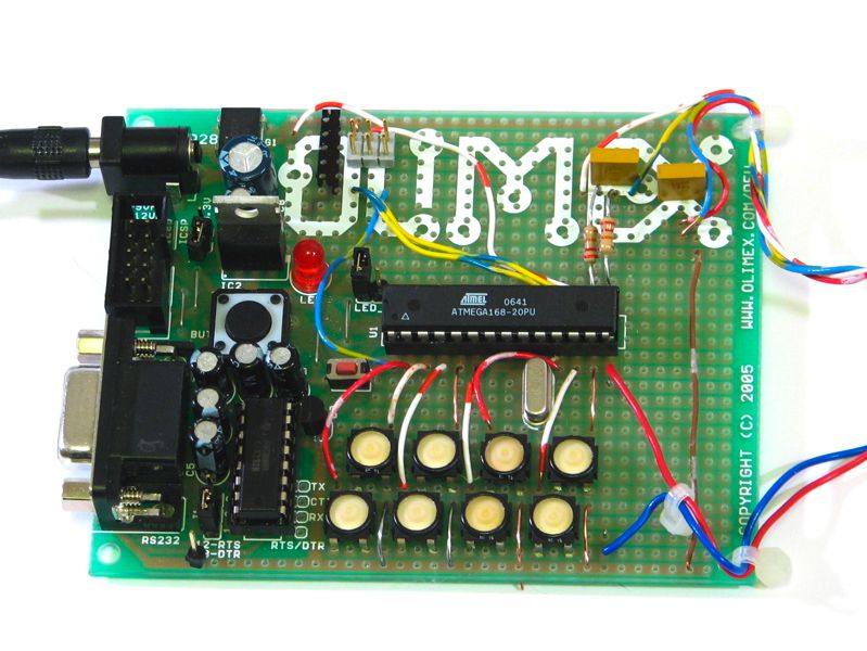
Typical varieties are these available from SparkFun Electronics, which are mostly made by Olimex. There is also an excellent board from Futurlec, and there are dozens of others from other sources as well. (Notably these excellent open-source reference designs by Pascal Stang.)
It’s often overkill. In the dev board shown here, I’m only using the power connector, socket and the ISP connector of the original board– none of the other features turned out to be handy for what I ended up building on this board.
So, when does it make sense to solder your own target boards? For starters, it’s easier to use through-hole (DIP) packaged AVRs.
One of the really nice things about the AVR series of microcontrollers is that a many of them are available in hobbyist-friendly through-hole (DIP) packages. (However, if do need to use one of the varieties that is only available in a surface-mount package, getting somebody else’s development board or laying out your own can really make sense.)
Let’s get started.
To begin with, we’ll make a minimal target board for programming an ATtiny2313, a popular 20-pin AVR microcontroller.
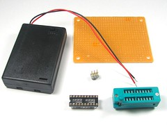
Here are the components: Prototyping perfboard (BG Micro part number ACS1053, $0.99), a 2×3 DIP header (Part of BG Micro part number ACS1019, $0.33), and a 20-pin DIP socket (BG Micro part number soc1029, $0.55). We also have a couple of optional components: a zero insertion force (ZIF) socket and a 3 x AAA battery box. ZIF sockets tend to be quite expensive– we found these on eBay for only a few dollars each, so we’ll actually build this board with one.

The first step is to position the socket and the ISP connector header on the protoboard, and then (important!) to mark one end of the ISP connector as being the end that contains pin 1. When you eventually hook up the ISP connector cable to the header, you will need to make sure that you have the correct orientation.
The next step is to determine how to hook up the pins of the ISP header to the pins of the socket. Atmel Application Note 42 describes the pinouts of the 6-pin and 10-pin ISP interface connectors. From above, they look like this:

The pins on the 6-pin interface are power (+Vcc) and ground, and the four “signals” of the ISP connector, which are called RESET, SCK, MISO and MOSI. You will notice that the 10-pin interface is just padded by a lot of fat– it doesn’t provide additional functionality.
(Note: The nature of the power (Vcc) line is context sensitive, and you will need to think about which way your power goes through that connector. If you are using the AVRISP mkII or most other programmers, the Vcc is expected to be provided from the target board to the programmer. This is used to indicate to the programmer that the target is “live” and ready to be programmed. If this is the case, you must provide a separate power source for the target board. If you use the USBtinyISP, you have the option to use the Vcc pin on the ISP interface to provide power to the target board. That option should be disabled if your target board does supply power to the Vcc pin of the ISP interface.)
Next, we need to identify the pins of the AVR that attach to those of the ISP connector.
You can begin by looking at the datasheet for your particular flavor of AVR ( list here) and finding the six pins that match up to the names of the pins on the ISP connector. Here, I’ve highlighted the relevant pins of three AVR devices that I happen to like and come in 8-pin (ATtiny45), 20-pin (ATtiny2313) and 28-pin (ATmega168) DIP packages:
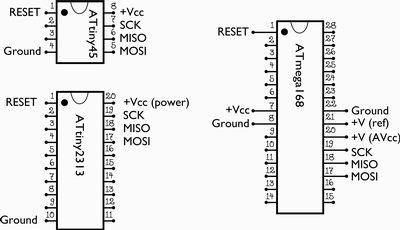
the ATmega8, ATmega48, ATmega88, and ATmega168 share the same 28-pin pinouts. Note that in the figure above there are more than six connections to the ATmega168. That’s because there are extra power and ground lines running to the analog circuitry of the chip, which should be wired up even when the analog section is not in use.
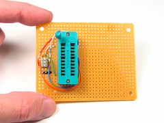 Now that we know where the various ISP pins of the header and the chip are, we can wire things up. We need six wires (obviously)– hook MISO to MISO, MOSI to MOSI, and so on, and solder up the lines. Remember to index the header from the end that you marked earlier, the end with pin 1.
That’s actually all there is to it– the rest is just icing.
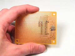
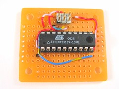
Here’s what the back side looks like; not much to look at!
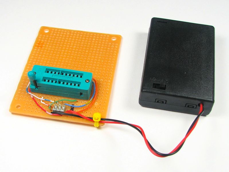
You can optionally add a power supply to power the board, which may be not-so-optional if you are using a programmer that requires power from the board. Since the chip uses so little power on its own, a battery box is a good idea and can last a very long time.
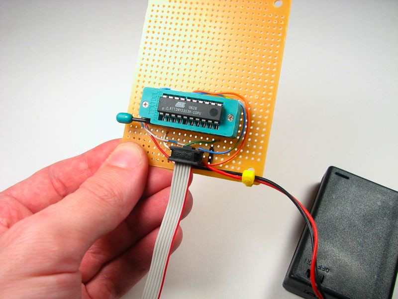
To use the target board, put the AVR in the socket and hook up the programmer to the ISP connector. Pay attention to the orientation. The end with Pin 1 is often marked with a stripe on the cable and/or a little triangle on the connector.

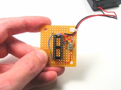
You can build a simpler, smaller, and much cheaper version of this target board by omitting the ZIF socket. It’s more difficult to use if you take the chip out *a lot* but otherwise it’s a good solution. And of course, if you are using a programmer that supplies power to the target microcontroller, you can even omit the battery box. Cost under $2 and assembly time under 5 minutes. Nice.
So where do you go from here? First, get that programmer if you haven’t already got one. Then install the GNU toolchain that’s appropriate for your system (e.g., winavr for Windows or OSX-AVR on the Mac), and then download some sample code and go to town– there’s no shortage of cool AVR projects out there, and we hope that that these hints will give a push in the right direction.
Update to this article:
Since publishing this, we have released printed circuit board versions of the ‘xx8 and ‘2313 breakouts shown above. You can read about these projects here and here, and kits are available on our web store here.
Our web store has also made available low-cost DIP ZIF sockets available, you can find them here.
> The killer feature versus the AVRISP mkII is that it lets you use the USB power to directly power your target board.
Hmm, how? I’d be happy to open my AVRISP and bring the right leads over, should be no big deal, I just want to not fry everything in my tiny little setup in the process. :)
That’s been done too, and you are certainly welcome to do so. I once found someone’s page where they showed how they put a voltage regulator inside and everything– but I neglected to bookmark it and haven’t been able to find it since. Too bad, I wanted to link to it. =(
—
Windell H. Oskay
drwho(at)evilmadscientist.com
http://www.evilmadscientist.com/
http://www.webx.dk/avrisp-mk2-modding/index.htm
Thank you! Thank you!
—
Windell H. Oskay
drwho(at)evilmadscientist.com
http://www.evilmadscientist.com/
That’s awesome except I can’t quite exactly tell the details there. If all I want is to pass the 5v usb right on through, does someone have a simplified version available? I am looking at the board of my (exact same) programmer right now, is the goal to just get 5v on the vcc pin of the 6-pin cable? Can’t be, that pin I assumed was to "sense" whether the chip was powered, not to power it, right?
You just want to pull the 5 V off the USB, and deliver that through the ISP connector to your chip, right? So just do that– use your multimeter and figure out which pin is +5 V and wire it up. You’ll have to cut whatever line *was* connected to that pin of the ISP connector.
—
Windell H. Oskay
drwho(at)evilmadscientist.com
http://www.evilmadscientist.com/
For beginners, the picture with "mark pin 1" might be confusing. Pin 1 is never at the end of the socket that shows the pen-mark. (maybe it’s something else, but it sure as hell shouldn’t be a pin-1 mark!)
That’s marking which end of the 6-pin header has pin 1; the sockets have a clear orientation already.
—
Windell H. Oskay
drwho(at)evilmadscientist.com
http://www.evilmadscientist.com/
Convention has it that pin 1 is usually placed where the ZIF lever is at, unless of course there is some mechanical reason that can’t be done. (although I think Australians may do it the other way around)
For newbies, you should mark pin 1, not just the end of the part, else a newbie could get confused and think pin 16 is pin 1. At the minimum confusing, at worst a complete fubar waiting to happen.
In every picture here that has a marking for the chip orientation, it’s right by pin 1. So… I’m not sure why you’re implying that I’ve made an error.
Where I say mark the end with pin 1, that’s referring to pin 1 of the 6-pin connector, not to the end of the chip. That’s pretty clear if you actually read it: "mark one end of the ISP connector as being the end that contains pin 1."
Windell H. Oskay
drwho(at)evilmadscientist.com
http://www.evilmadscientist.com/
Dumb question here, but how do these chips run with no external oscillator? The ATtiny2313a documentation lists different speed grades for different supply voltages; does the chip pick some default based on the supply voltage, or is it programmable, or default to a particular value in the absence of an external oscillator, or what?
Thanks!
The ‘2313, like most (if not all?) AVR microcontrollers, has an internal RC oscillator that it operates from by default. The default clock rate is 1 MHz, but you can also set it as high as 8 MHz with the internal oscillator. If you need more stability than the RC oscillator provides, or you want to run at a different and specific clock rate, you can add an external oscillator to the ‘2313.
The different speed grades refer to how fast they are capable of running with an external oscillator present.
Windell H. Oskay
drwho(at)evilmadscientist.com
http://www.evilmadscientist.com/
eBay is a PITA. SparkFun sells 40-pin 0.6" DIP ZIF sockets for $4 each, and 28-pin 0.3" for $3. Way cheaper than DigiKey or Mouser…
You can also find them at our own web store here.
Windell H. Oskay
drwho(at)evilmadscientist.com
http://www.evilmadscientist.com/
Can I use this interfeace long with AVRdude program to read program from already programmed controller(ATTINY12)?
Usually yes. However, it’s possible to "lock" the memory such that it can’t be read out without erasing it first.
Windell H. Oskay
drwho(at)evilmadscientist.com
http://www.evilmadscientist.com/
I’m using 10-pin and trying to make a target board for a ATmega168. So my questions are:
1. Do i need the (NC) pin? I don’t, right?
2. What are those +V (ref) and +V(AVcc) ?
NC means "no connection." The Vcc lines are +5 V, or really 3-5.5 V depending on configuration. The "analog" lines can be hooked up to separate or isolated power if desired. Otherwise, just hook them up to the regular power supply.
Windell H. Oskay
drwho(at)evilmadscientist.com
http://www.evilmadscientist.com/
alright thanks a lot !
go to youtube and check out the eevblog. I’m sure he has a video that does exactly what you describe.