


One of our favorite projects of the last year is our Bulbdial Clock, an LED shadow clock based on an idea from Ironic Sans. And, while we have written a fair bit about it, we haven’t yet taken the time to describe some of the interesting technical details.
So in what follows here, we discuss some of those details, with an emphasis on a few in particular that we’ve been asked about. First, the process of designing and prototyping “funny shaped” circuit boards, but also charlieplexing LEDs in a mixed array, and (finally) getting that rear-projection scheme to work.
First up: How do you make circuit boards that aren’t rectangular?
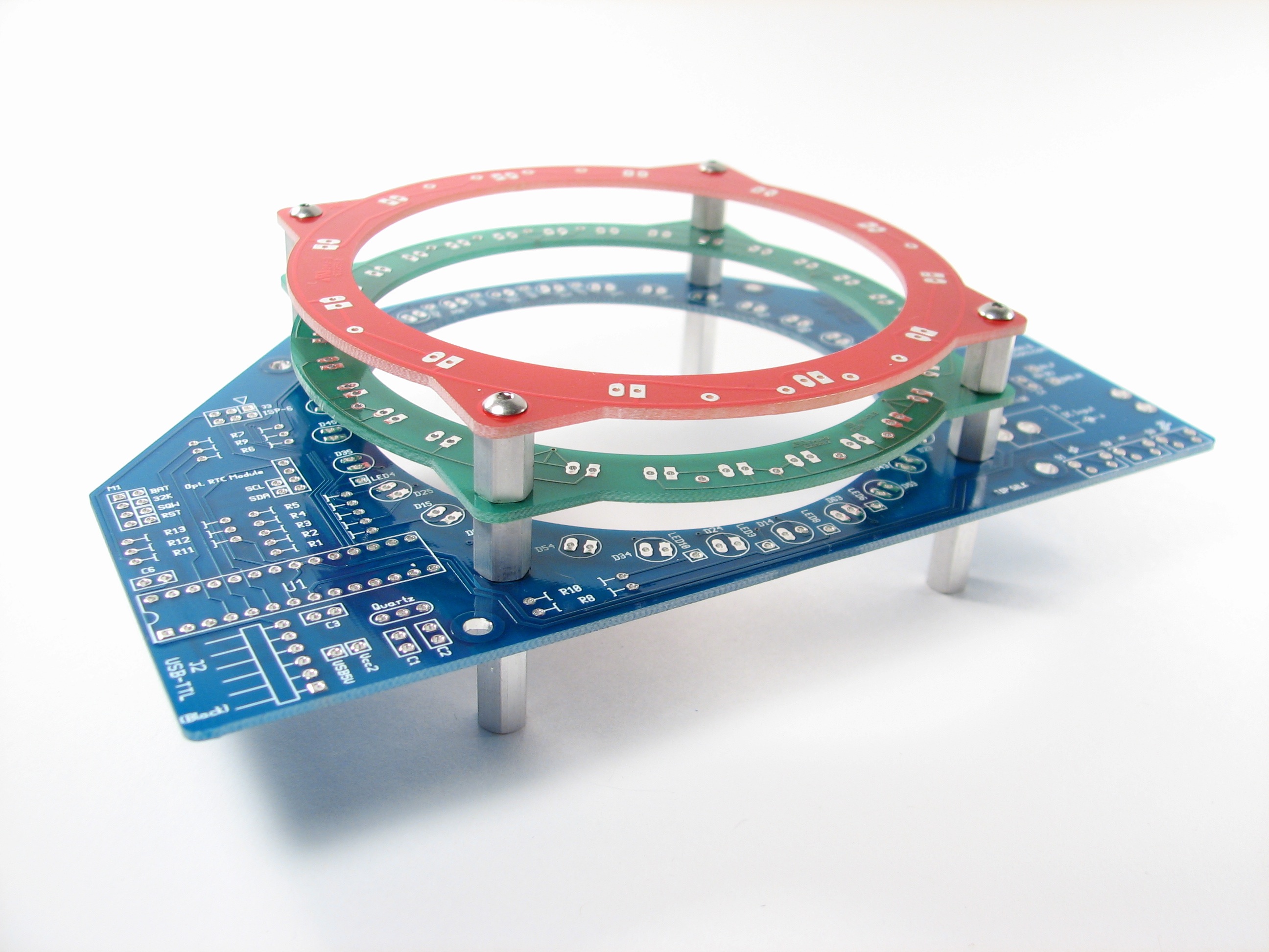
If you look at the printed circuit boards above, you’ll notice that they’re anything but rectangular.
They have complex routed shapes and internal routing as well: a big hole in the middle of each board. The standard low cost (“no touch”) prototype services from most PCB fabricators allow only rectangular boards, and no internal routing.
There are, of course, more expensive (“full-service”) proto services, but suppose that you have a complex design like this. With three separate circuit board designs, the cost of three separate full-service PCB runs adds up very quickly. So this leads to a separate question from how to design the boards, which is how to *prototype* and them at a reasonable rate.
It turns out that at least one PCB fabricator, Sunstone Circuits— and their excellent PCBexpress service in particular allows fully routed outlines on prototype PCBs at no extra cost. They do not, however, allow internal routing, so we needed another solution for that part.
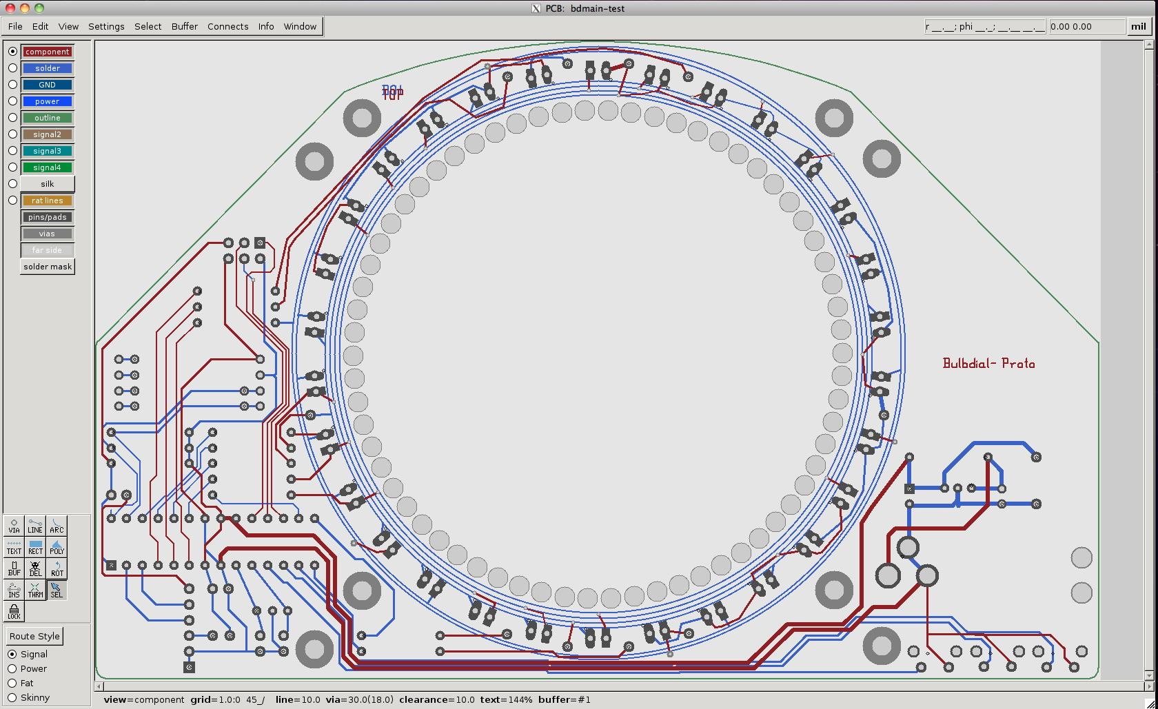
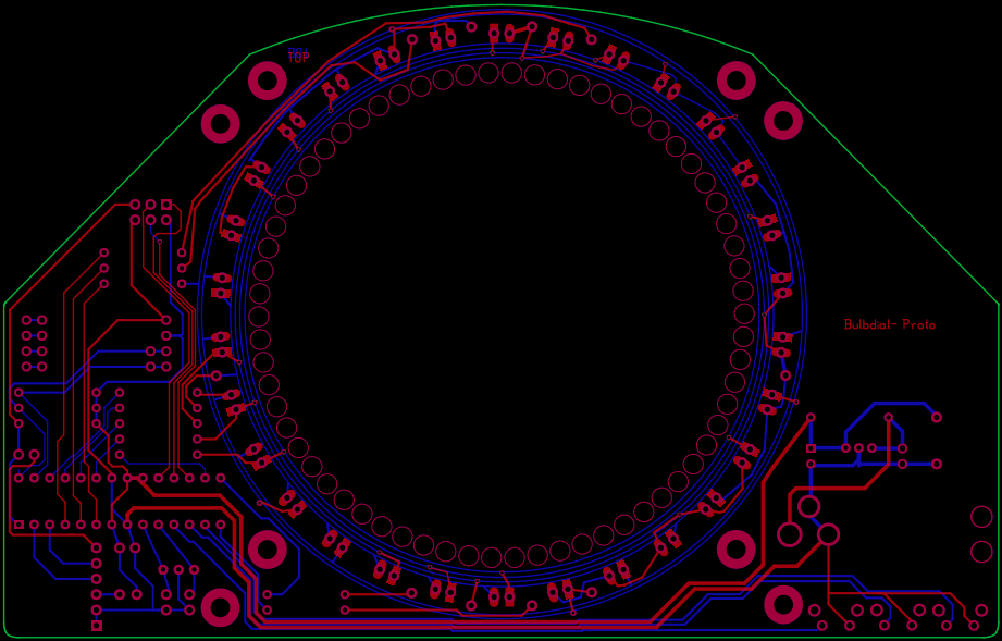
Here’s what we came up with: a ring of large-diameter drilled holes that *almost* punches through. (A ring of circles that *does* punch through is called a “canned circle”– explicitly disallowed at sunstone.)
The layout screenshot above is from gEDA PCB, showing the larger main board.
Here is how it looks in gEDA gerbv.
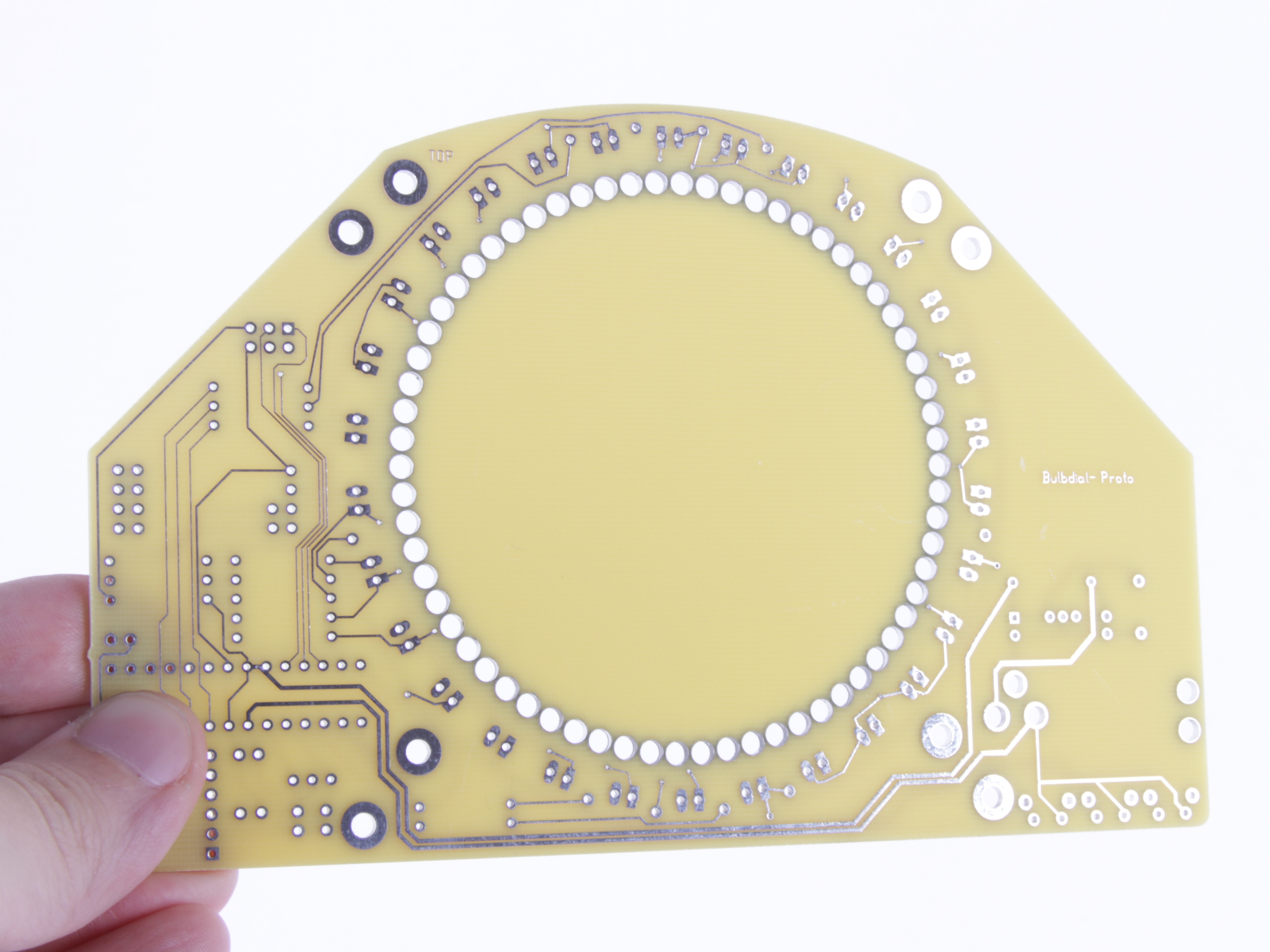
And finally, a few days later, here’s how it looks as the board arrives. As you can see, we opted for the PCBexpress E1 — two layers, no soldermask, no silkscreen, 1 day turnaround –option. It’s a great deal. A far cry from the finished product, but perfectly sufficient for testing mechanical layout and electrical design.
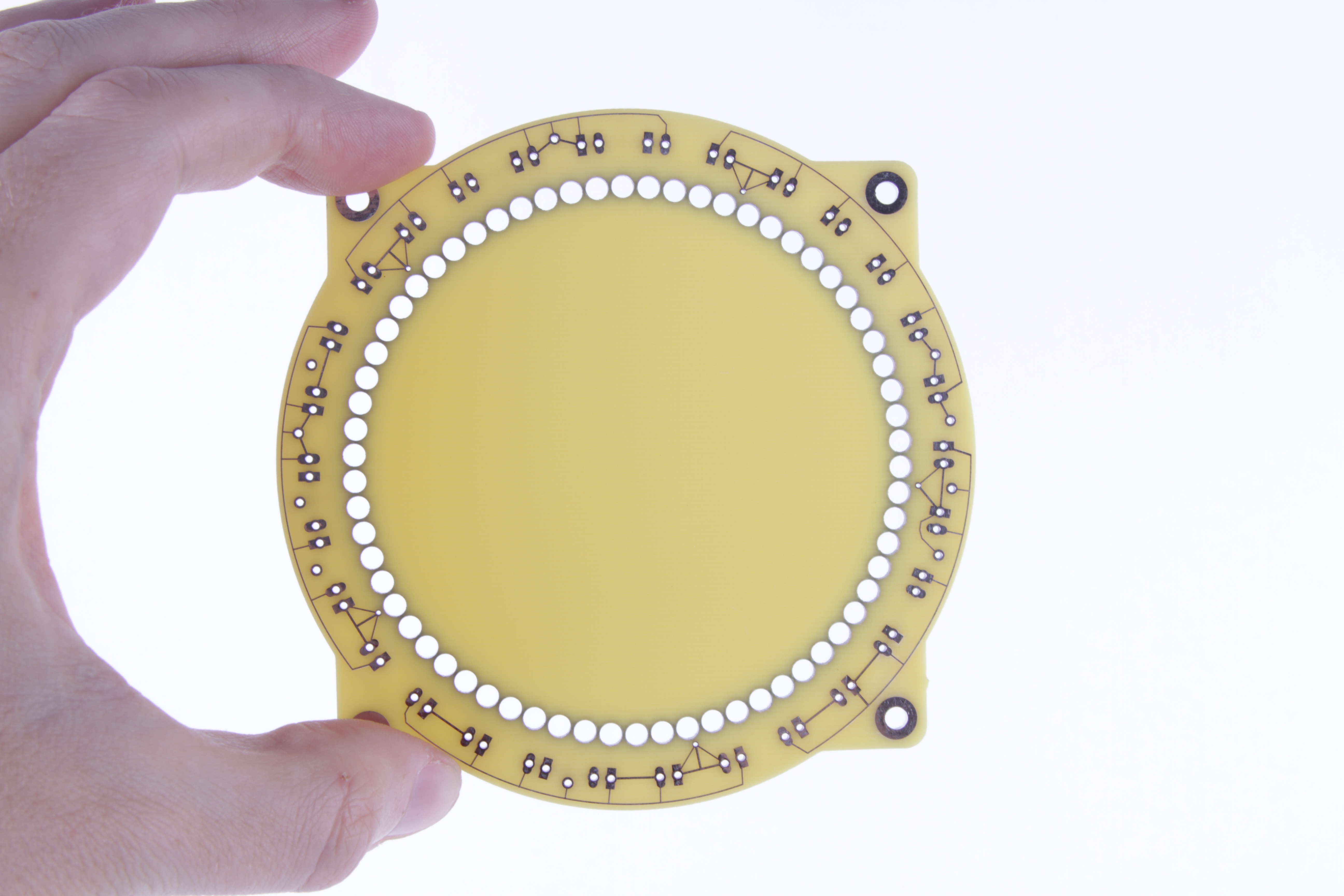

Here are the other two boards– for minutes and hours –done in the same process.
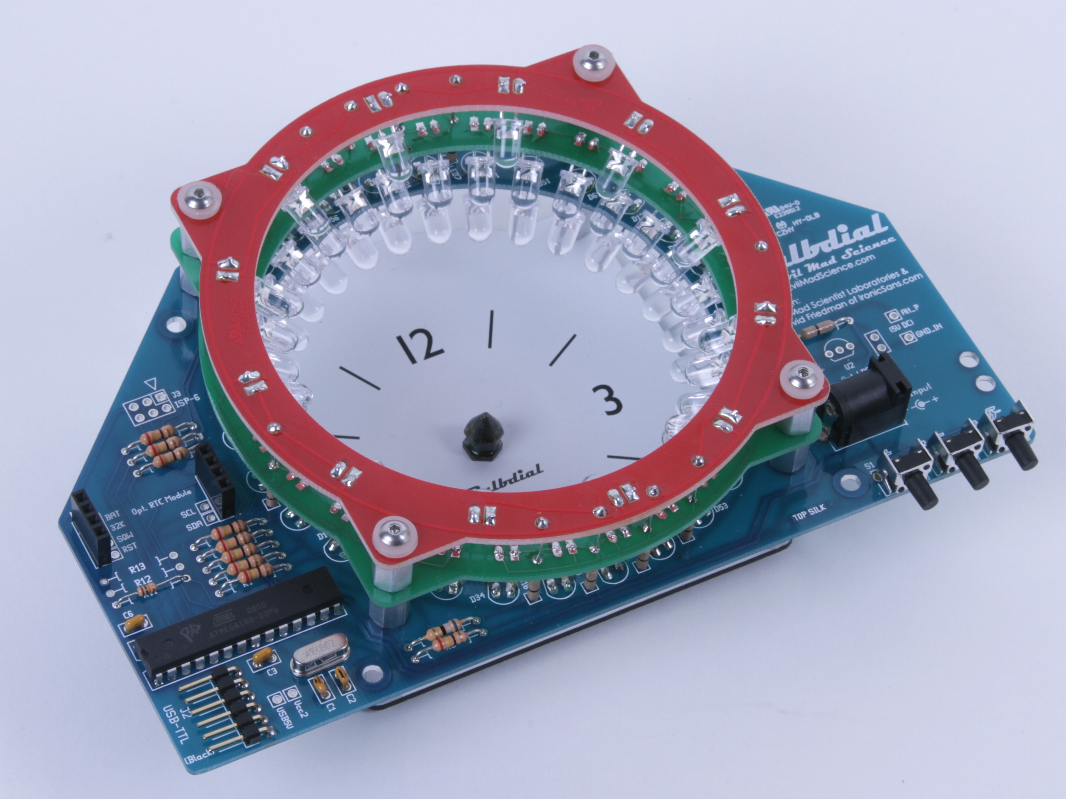
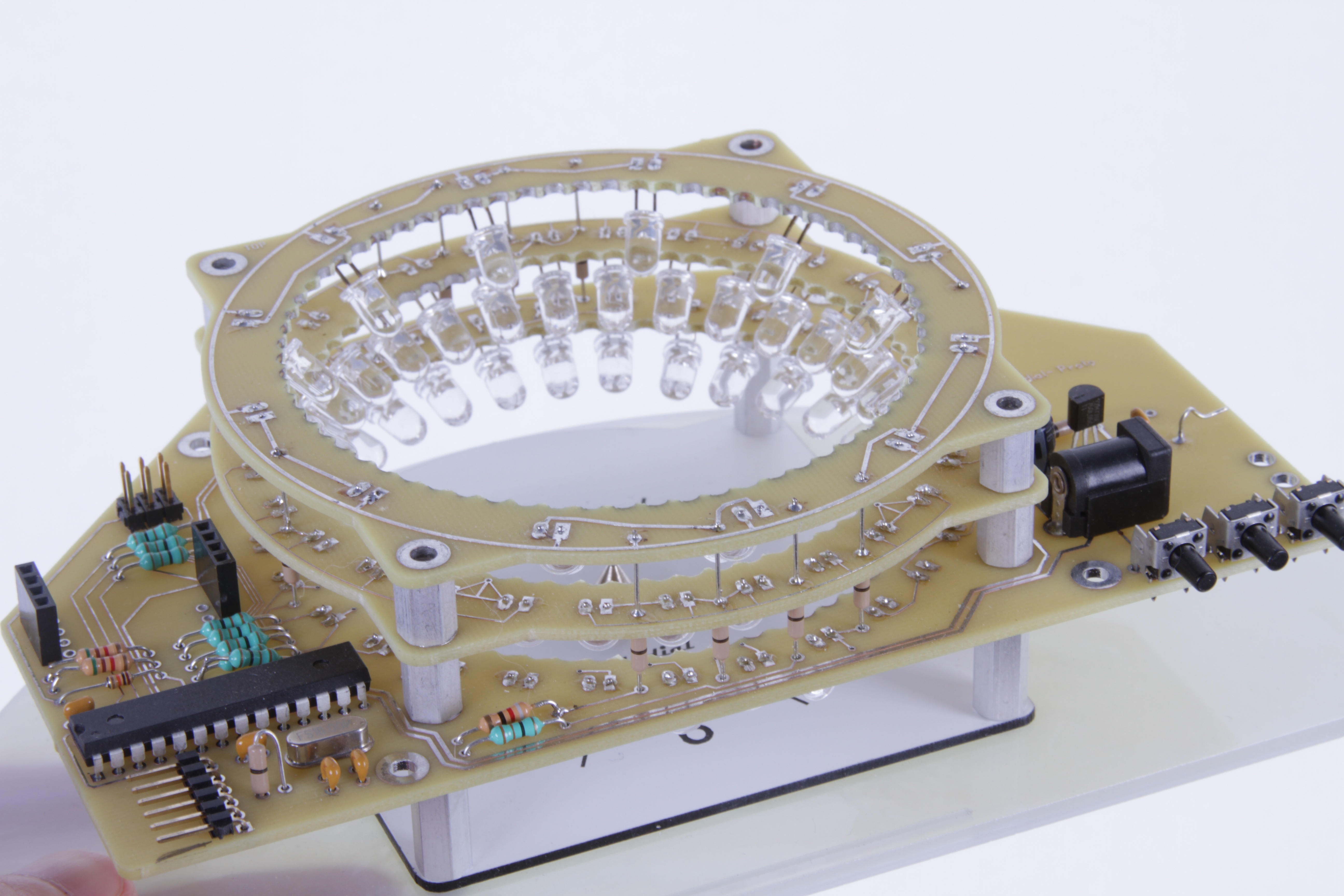
From this point, it’s possible– but not trivial –to use clippers to take out the little bridges holding the center disk in place. And then, to build up the working (but not yet beautiful) prototype:
After prototyping and testing comes the final version. While the external routing is easy in production quantities, it’s not immediately obvious how you specify internal routing. External routing of the board outline is typically specified in either the “drill drawing” (sometimes called “fabrication drawing”) gerber layer, or can be done in a separate layer that just contains the outline. For internal routing, you put the drawing on the same layer and clearly indicate– because this will be read by a human –which parts go and stay.
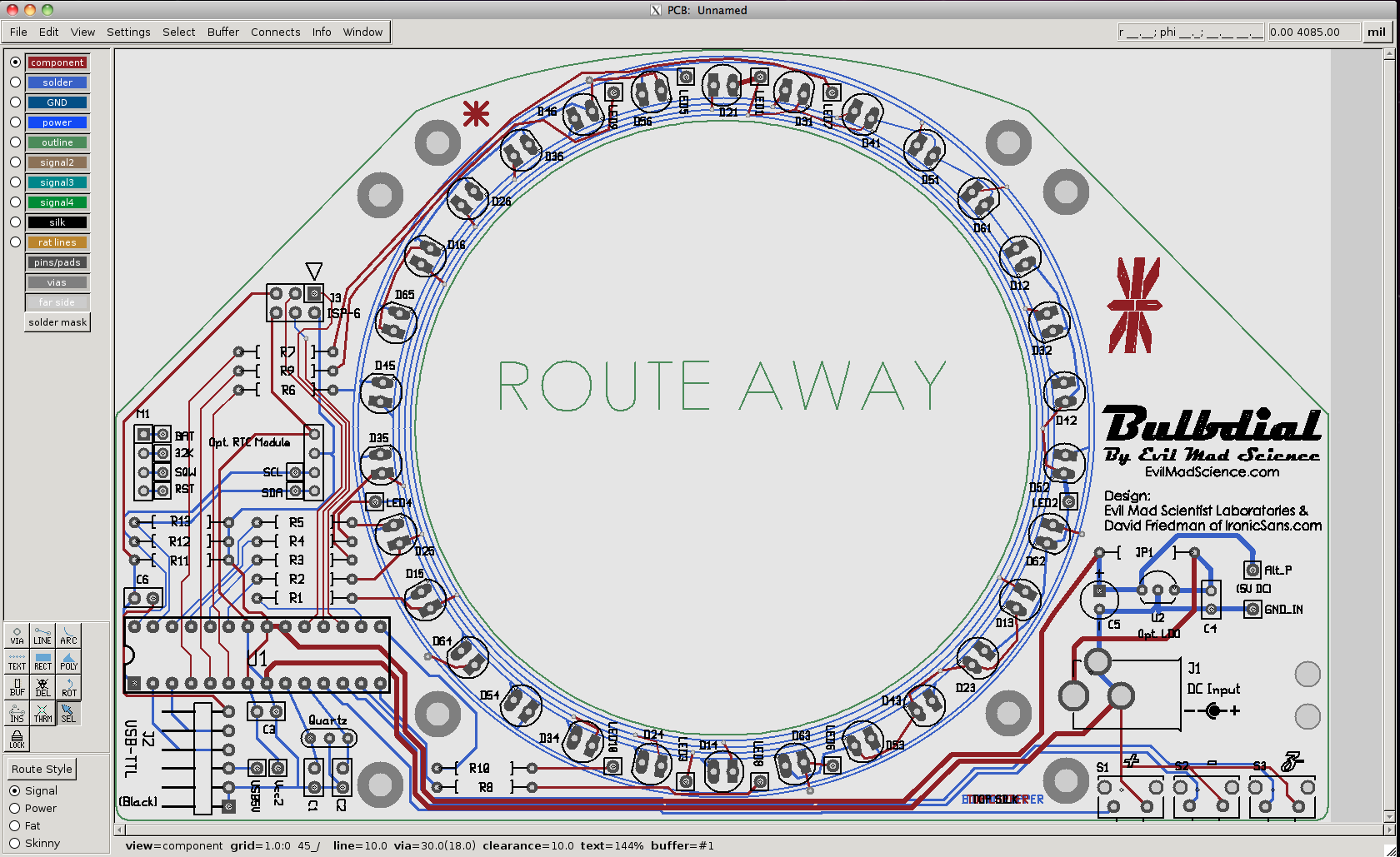
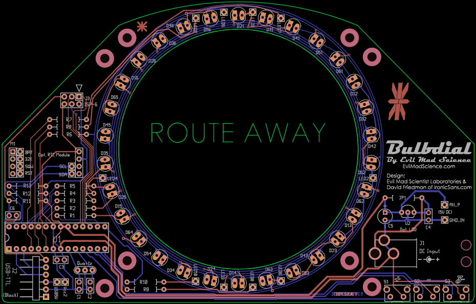
In the screenshots above, from the final layout in PCB and gerbv, you can see an example: the board outline (green) has an inner cutout, labeled by the words “ROUTE AWAY.”
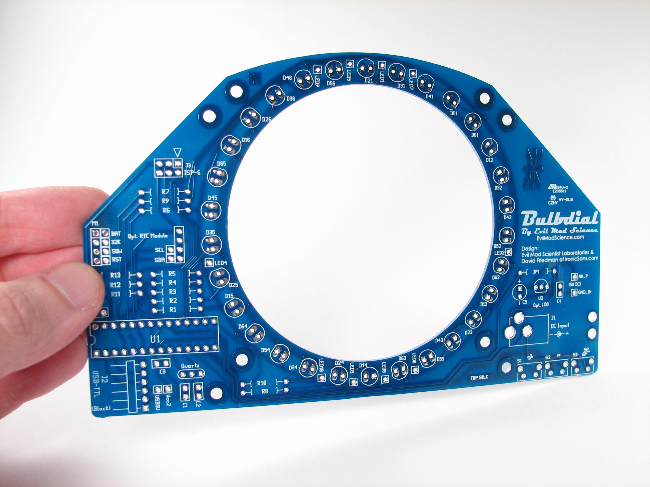
And here’s how that design comes back in the final version.
A note on charlieplexing.
The Bulbdial clock has a grand total of 72 LEDs: 12 hour (red), 30 minute (green), and 30 second (blue). However, only a few of them are on at any given moment, because our clock only needs to display one LED at a time on each ring, or perhaps two as it fades between them. This setup, with a large number of LEDs and very few operated at a time is the perfect situation for charlieplexing.
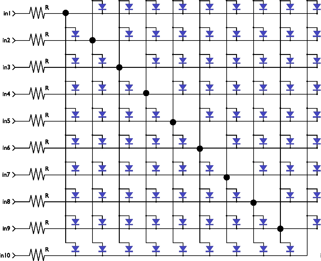
In the clock we have 10 lines available to control LEDs. This can potentially drive up to 90 LEDs in the configuration shown. Each line passes through a resistor before connecting to a row and column of the matrix. Because each LED is driven between two lines of the chip, each LED is effectively in series with 2*R (the resistance of each resistor), and the voltage that the chip can supply. This works very well if every LED is the same type and has the same forward voltage and current requirement. But what can you have an array with different types of LEDs?
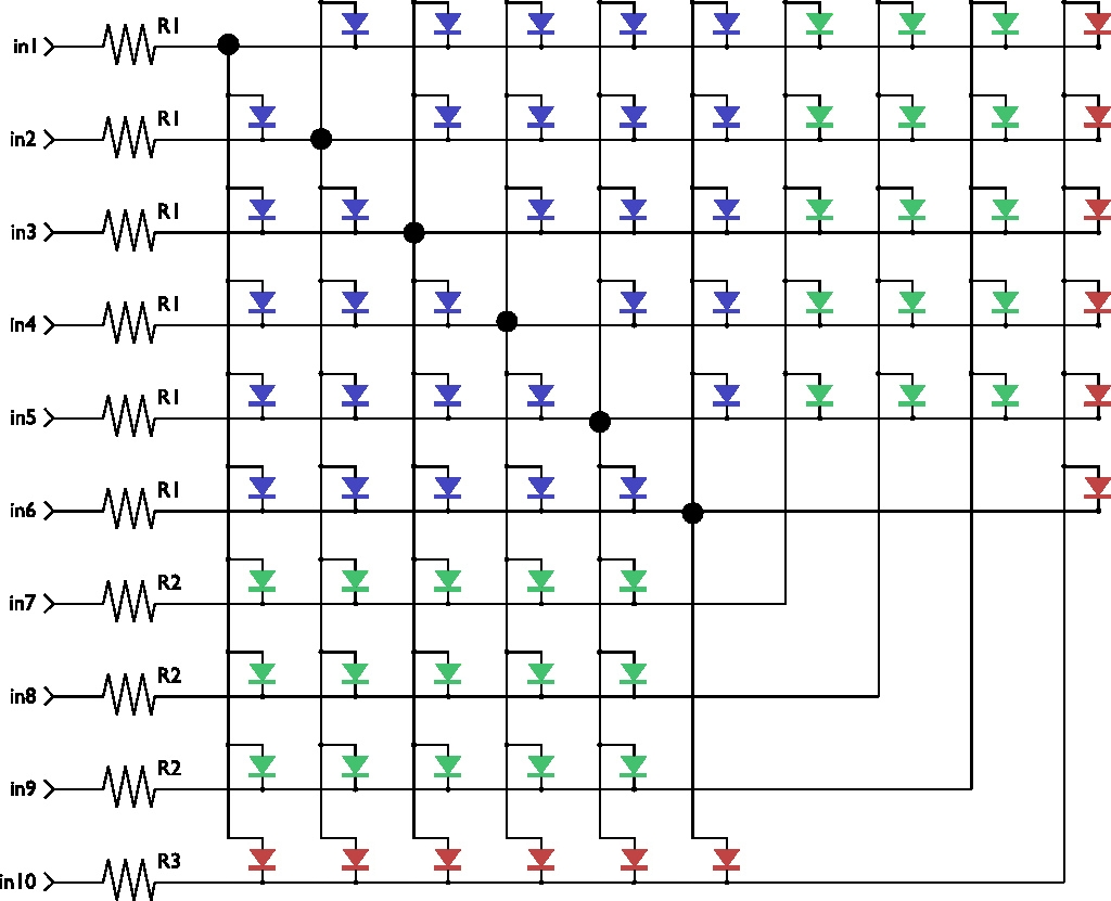
Here is one way to handle the different LED requirements: to segment the LED grid into different portions that have different series resistance.
This scheme is used on the Bulbdial clock, which has different resistors suitable for the different colors of LEDs used. The blue LEDs are all on lines 1-6, so that each has series resistance 2*R1. The green LEDs are between lines 1-5 and 7-9, such that each has series resistance R1+R2, which can be a different value. The red LEDs are between lines 1-6 and 10, so each red LED is driven through series resistance R1+R3, which can be another different value.
This scheme allows us to pick and choose the correct resistor value, independently for all three colors. It is worth noting that we’re only using as many LEDs in this scheme as we need; 72 of 90 possible spots. It’s also worth noting that LEDs are usually fairly tolerant of overcurrent pulses of short duration, so getting the resistors “just right” is not necessary in any situation where you can guarantee that they’ll be scanned all the time. By contrast, the Bulbdial clock circuit is hackable and reprogrammable, so we want to make sure that the LEDs will be happy even if driven continuously.
Rear projection
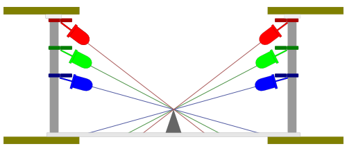
This diagram shows a cutaway view of the Bulbdial clock, showing the basic geometry of the LEDs and gnomon (the pointy spike in the middle). The LEDs hang below the three rings, and the red ring (top) makes shorter shadows than the blue ring (bottom).
In the most obvious scheme you view this from the top, looking down towards the spike, and see the shadows on the clock face. However, we had an initial goal of also supporting a “rear projection” mode, where you use a translucent clock face and view it from the bottom. While this is easy in principle, it turns out that finding the right material for that translucent clock face was anything but trivial.
We tried paper, masking tape, sanded clear acrylic, engraved clear acrylic with different patterns, white acrylic of different thicknesses, wood veneers, phosphorescent materials, various translucent plastics like acetal, polypropylene, nylon, multiple layers of these different materials, and a number of others. All with very poor results.
It turns out that two major problems kept occurring, and we often had both in the very same materials. First, many of the materials were simply too opaque. Our LEDs are very bright, but the projected pattern was simply not clear enough in most cases. The second problem is that most of the materials did a very poor job of producing clearly diffused projected spots. Imagine, if you will, using the rear projection scheme when it’s 3:45 PM and the clock face is made of polypropylene (mostly clear; about the color of a 95% water, 5% milk solution). The red LED (hour hand) is facing towards the right, and the green LED (minute hand) is facing towards the left. Because the material diffuses the light weakly, you can stand in the middle and not see either hand clearly, but if you lean right you’re blinded by red light, and if you lean left you’re blinded by green light. That’s an extreme case, but the same terrible asymmetry was found in many of the materials that we were sure would work well.
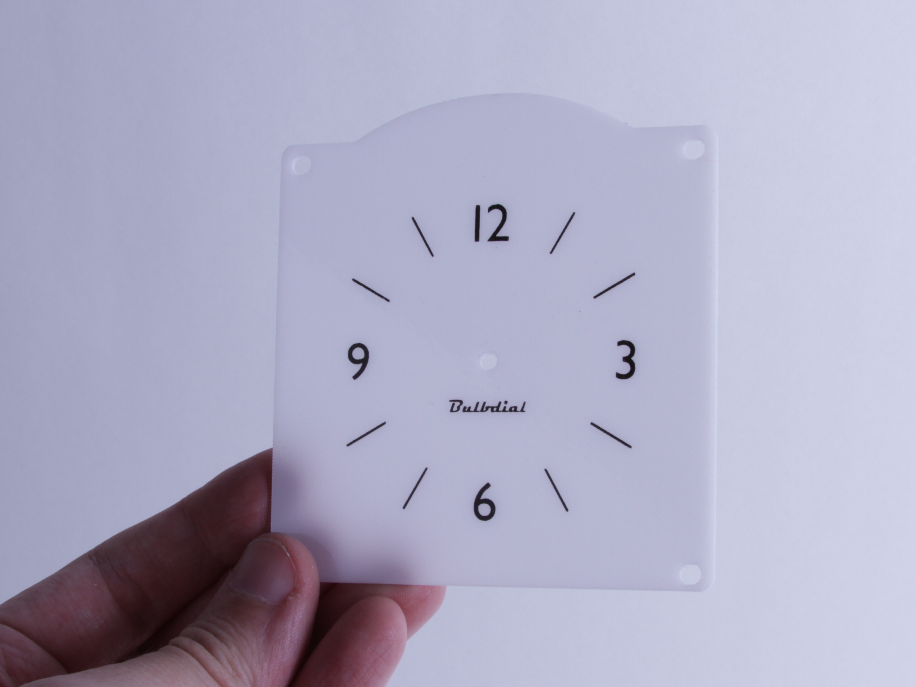
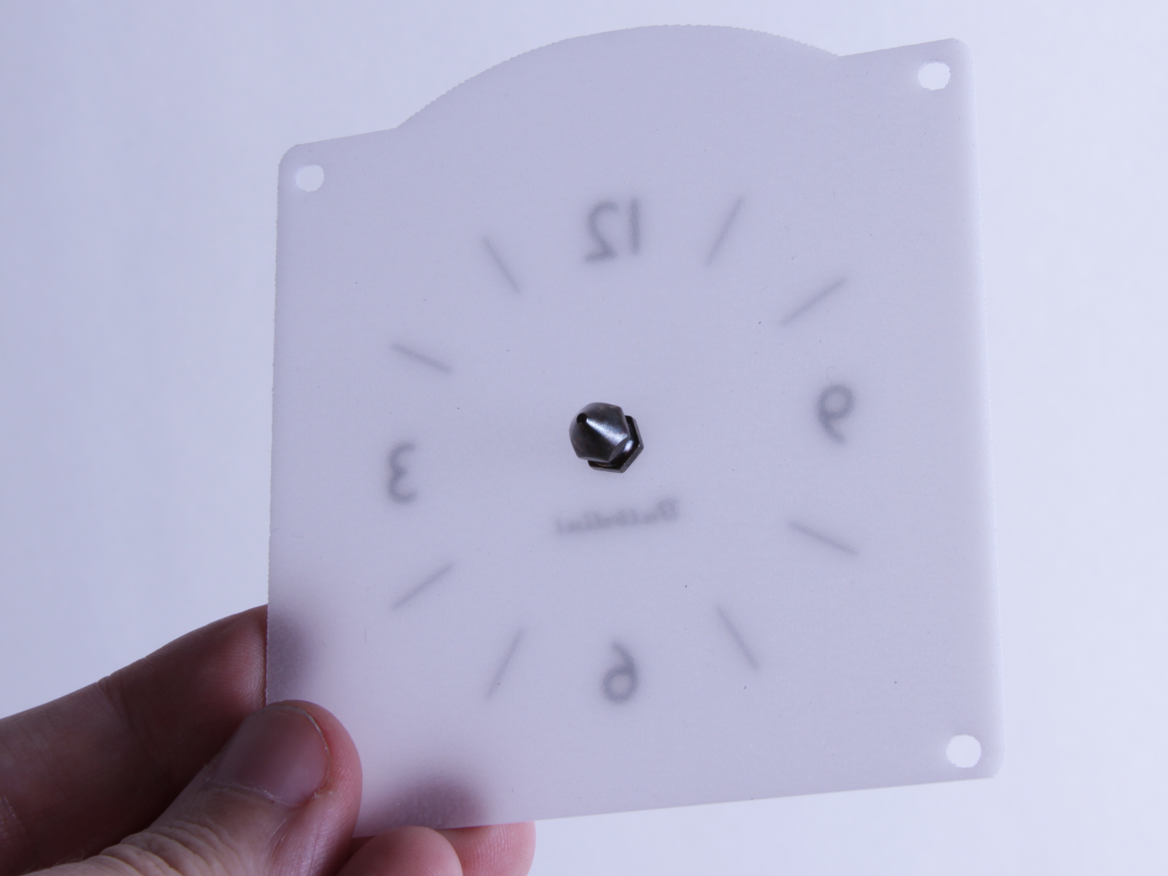
We finally did find one material that works well. It’s a 1/16″ thick acrylic diffuser panel, designed to go underneath fluorescent lights in dropped ceilings. The material is heavily textured on one side, smooth on the other, and it has a pleasant translucent quality to it. Presumably the pigment in this particular material is optimized for scattering light, because it really works like a charm.
We had the clock faces laser cut for us and screen printed on the smooth side, so that the textured side points towards the lights. In the pictures above you can see how it looks from both sides, complete with the gnomon on the right side.
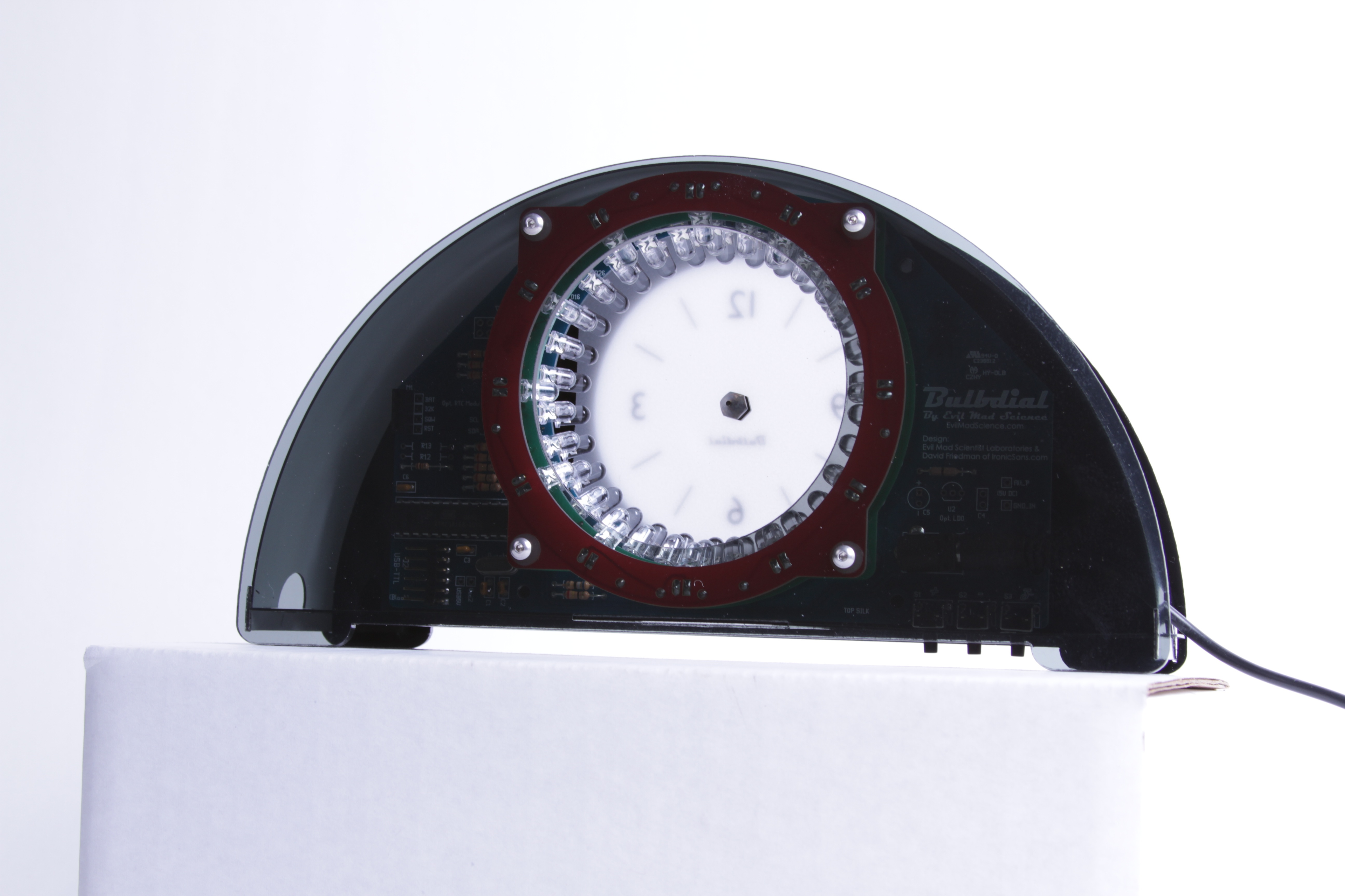
Here’s the clock face installed on the clock– you can leave the back side open to see the works or shut up to keep it mysterious.
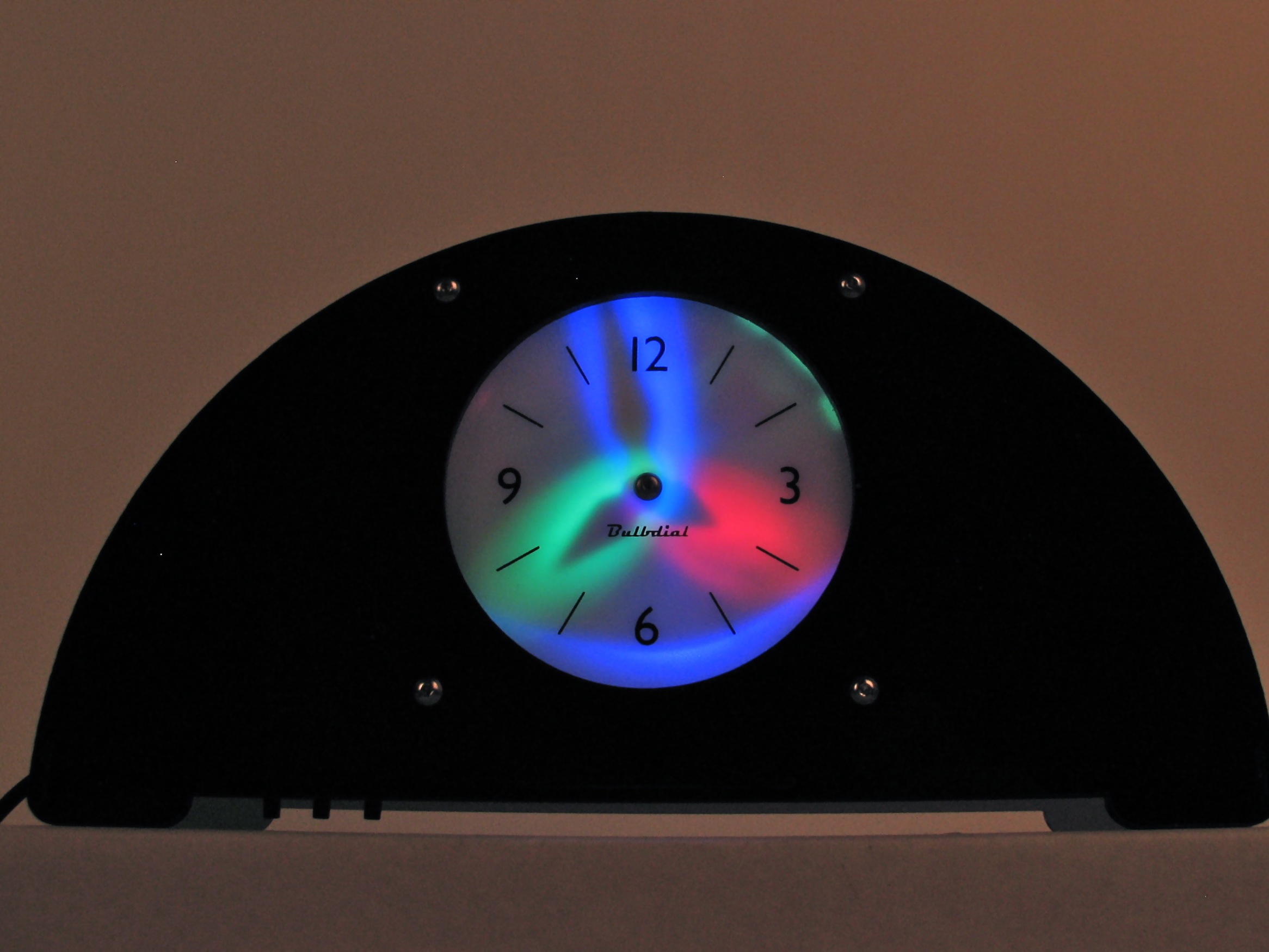
And finally, here’s how it looks mounted inside a black case.
(Note: photo is a bit dark because it’s normal room lighting; superbright photography flashes light up a translucent faceplate way better than LEDs!)
The Bulbdial Clock Kit is available at our web store here, and the new rear projection faceplate is now available here.
I love my bulbdial, but it can be hard to read the time from far away and off to the side, due to the inset depth of the clock face. I’m so happy you finally got rear-projection figured out! I just ordered the face and can’t wait to install it.
I love my Bulbdial too. I find when I’m off to the side, I can see the green LED but not it’s shadow, so I mentally reverse it to get the minutes, which is really the part of time I need to know.
Has anybody tried interpolating the hands continuously to get a more analog appearance? I kinda know how to do it, but since I program for a living, that’s too much like actually working so I haven’t gotten around to it.
The biggest hindrance to this is the fact that there are only 12 LEDs to display the hour, so you can’t necessarily get the precision that you might need to get an analog "hour hand". Ideally, you would want at least 12 more LEDs, so that you could display Top of hour (Current hour’s LED), Quarter past (Current Hour LED + Half-past LED), half-past (Half-Past LED), and Quarter Til (Half-Past LED + Next Hour LED).
In theory, you might be able to somewhat substitute an extra Green layer for the Red layer, but wiring would be somewhat of a pain, given that the current boards are specifically designed with only 12 risers on the Green layer to go to the Red layer. One could combine elements of the Blue layer with the Green layer to add the extra "risers" to the third ring, since it’s an open-source project, and then custom-print a new Green and Red PCB.
You might also need to add wiring to the Blue PCB, but it’s been a while since I was poking around in the design files. Because it’s Charlieplexed, as long as you don’t add more than 18 additional LEDs to the top ring, you should be fine, and you MIGHT be able to get away without adding wiring to the Blue layer.
Or, I suppose you could try to just re-program it and use PWM to fade between hours (100% on, 75/25 current/next, 50/50, 25/75), but I honestly don’t know if you’d get the precision you’re looking for without adding more LEDs to the Red layer. Obviously, the cheaper solution, dollar-wise and time-wise, would be to reprogram it to PWM fade. Then you could decide if it looked right or not, and go from there.
The rear-projection panel just arrived, I installed it in minutes, and it looks great! I can read the time from across the room and off to the side.
As an added bonus, the clear panel on the back now reveals all the circuitry (instead of just the back of the circuit boards), so it looks even cooler when you’re showing it off. :)
Way to go, guys!
Great article! Really enjoyed reading about the "behind the scenes" details, as I’m working on a clock kit of my own.
Kudos also to your interactive Game of Life table, I particularly like the modular design approach.
Cheers from Canada,
Andrew O’Malley
http://www.technoetc.net/blog