


Zener diodes are a special type of semiconductor diode– devices that allow current to flow in one direction only –that also allow current to flow in the opposite direction, but only when exposed to enough voltage. And while that sounds a bit esoteric, they’re actually among the handiest components ever to cross an engineer’s bench, providing great solutions to a number of common needs in circuit design.
In what follows, we’ll show you how (and when) to use a Zener, for applications including simple reference voltages, clamping signals to specific voltage ranges, and easing the load on a voltage regulator.
Background: Semiconductor diodes, real and ideal
To understand how Zener diodes are different from other diodes, let’s first review the properties of regular diodes. And, while there are many different types of diodes– see here for a long list –we’re going to focus on so-called “normal” semiconductor diodes, most commonly constructed with a p-n silicon junction.
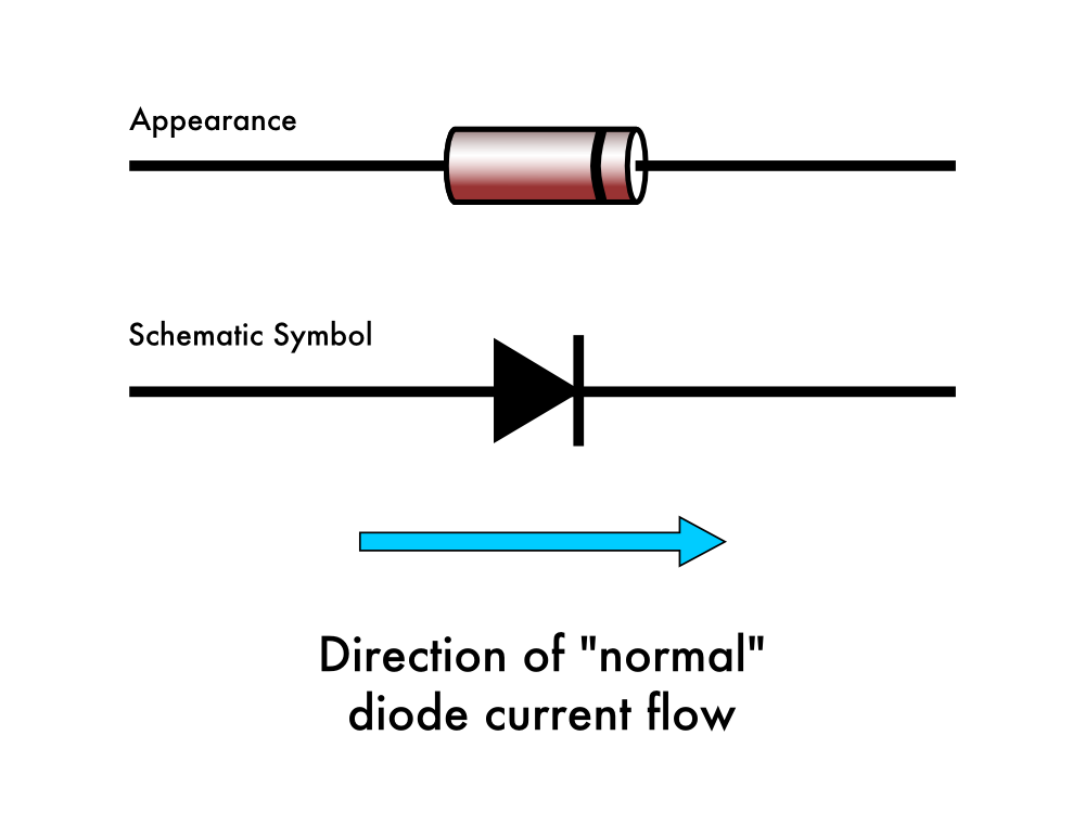
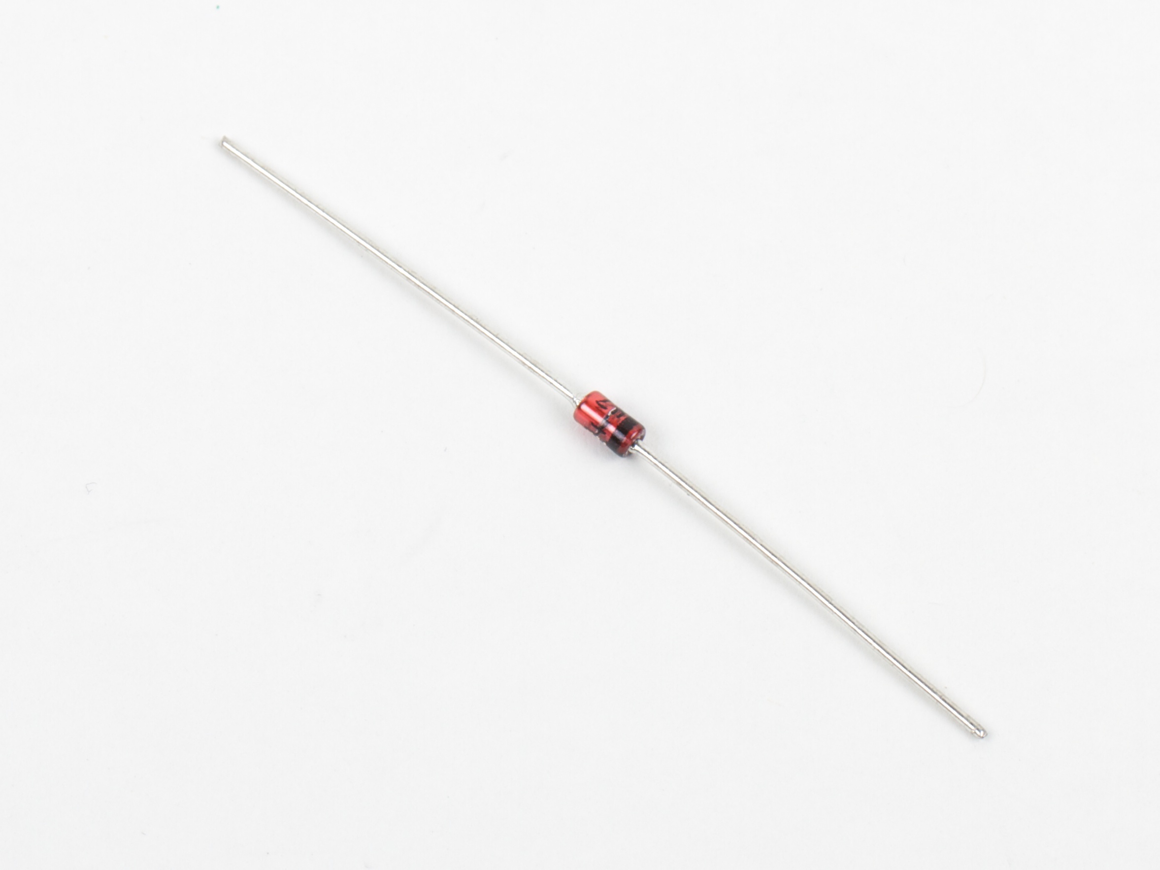
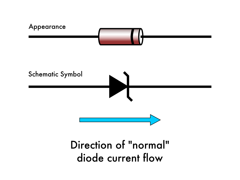
Diodes usually come in glass or plastic cylindrical packages, marked with a stripe on one side to indicate polarity. In a perfectly ideal diode, current flows in one direction only, from the anode (positive side) to the cathode (negative side) which is marked with the stripe. The schematic symbol is a triangle pointing towards a bar, where the current flows in the same direction, towards the barred (striped) end. Surface mount versions of diodes tend to follow the same labeling convention, where the cathode end is marked with a broad stripe.
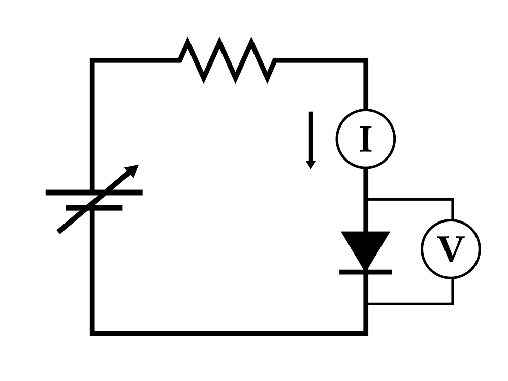
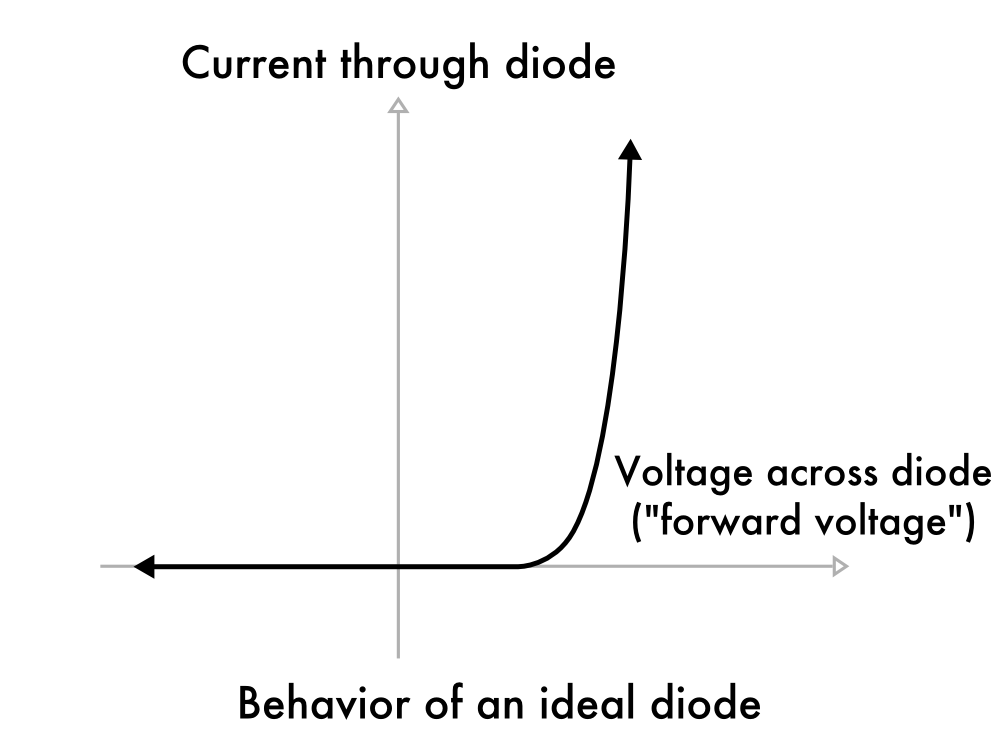
If we hook up a diode in a simple circuit with a variable voltage source and a current-limiting resistor, we can measure the current I through the diode when a given voltage V is applied across it. For an ideal diode, no current at all passes when the voltage is less than zero: the diode completely prevents reverse current flow. For small positive voltage (“forward bias,” or sometimes “foward voltage”), a tiny amount of current may flow, and a very large amount of current will flow above a given threshold. The amount of current that flows is actually exponential with increasing voltage.
The threshold where an appreciable amount of current flows is typically around 0.7 V for simple semiconductor diodes, but may be as low as 0.15 V for Schottky diodes, or as high as 4 V for certain types of LEDs.
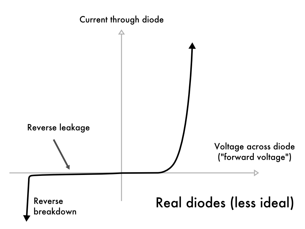
Of course, no diode is truly ideal. In real diodes, when the voltage is reversed, a very small amount of current (leakage) may flow. And, more significantly, each diode is rated for a certain maximum amount of reverse voltage. If you apply voltage more negative than that limit, the diode will undergo “reverse breakdown” and begin to conduct a significant amount of current, but backwards from the normal direction of diode current flow. For a regular diode, we would say that the diode has failed if it begins to conduct current in that direction.
Aside: The actual physics of what happens at breakdown is quite interesting; two separate effects, the Zener effect and Avalanche breakdown both contribute to this behavior.
Zener diodes
Zener diodes are semiconductor diodes which have been manufactured to have their reverse breakdown occur at a specific, well-defined voltage (its “Zener voltage”), and that are designed such that they can be operated continuously in that breakdown mode. Commonly available Zener diodes are available with breakdown voltages (“Zener voltages”) anywhere from 1.8 to 200 V.
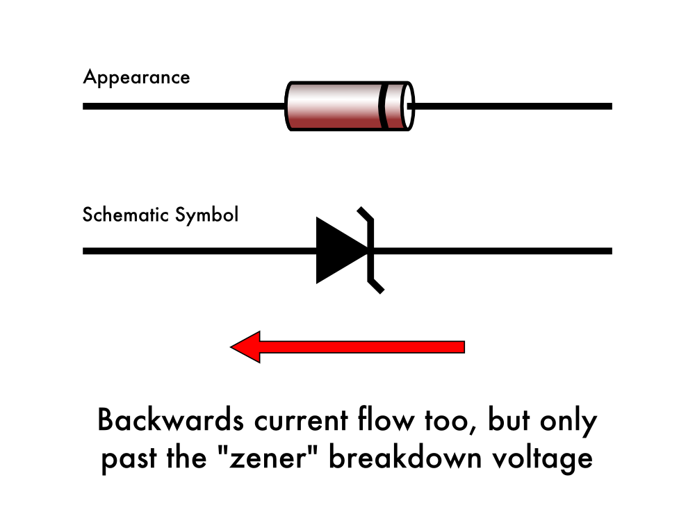
The schematic symbol for a Zener diode is shown above– it is very similar to that of a regular diode, but with bent edges on the bar. The Zener still conducts electricity in the forward direction like any other diode, but also conducts in the reverse direction, if the voltage applied is reversed and larger than the Zener breakdown voltage.
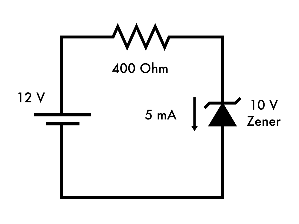
A typical application might be as above: A 10 V Zener diode (type 1N4740) is placed in series with a resistor and a fixed 12 V power supply. The resistor value is chosen such that several mA flow through it and through the Zener, keeping it in its breakdown region. In the circuit above, there is 10 V across the Zener diode, and 2 V across the resistor. With 2 V across a 400 ohm resistor, the current through that resistor (and the diode, in series) is 5 mA.
Zener voltage references
The fixed voltage property of Zener diodes makes them extremely handy as quick voltage references. The basic circuit looks like this:
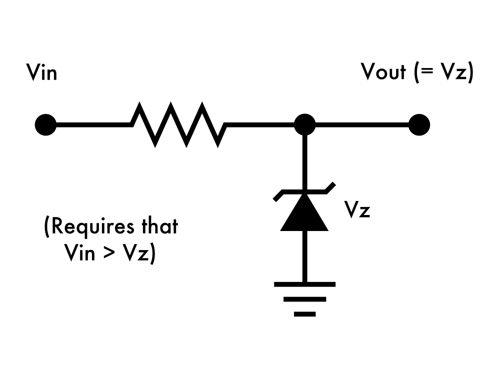
There are a couple of requirements to consider. First, the input voltage has to be higher than the Zener voltage. Second, the resistor value must be chosen such that there is always current flowing through the Zener.
Some caveats: This is not necessarily a good power supply for all purposes– the resistor limits how much current can be drawn. It is also not necessarily a precision voltage reference; the voltage will depend on the amount of current drawn. (That is to say, for the voltage to be steady, the load driven by that reference voltage must be consistent.) The voltage also depends upon the temperature. Zeners in the range 5-6 V have the best temperature stability, and there are high-precision Zener diodes (like the LM399) that include their own temperature-stabilized oven to further keep the diode temperature as steady as possible.
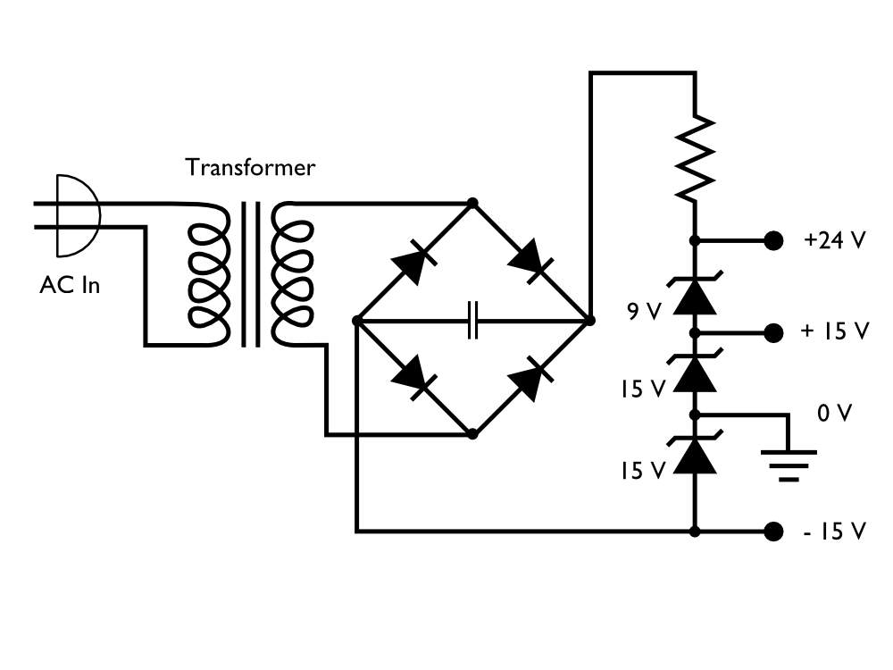
Taking this idea a bit further, you can actually build a full multi-rail power supply using nothing more exotic than a set of Zener diodes to generate all the voltages that are needed, provided that the current requirements are modest on the different supply voltages. The circuit above is part of a working laboratory instrument.
Voltage clamps: Limiting signals with Zener diodes
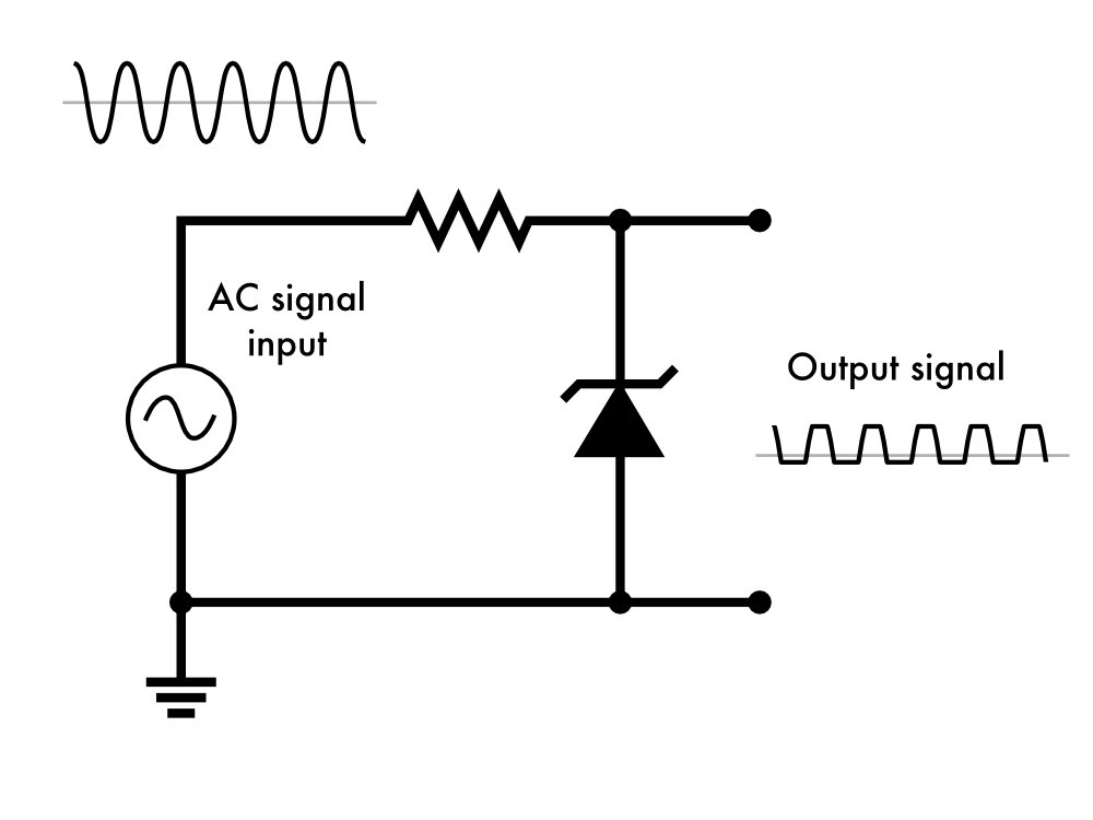
A varying analog signal can be constrained to a fairly narrow range of voltages with a single Zener diode. If you have a voltage that swings between + 7 V and – 7 V, you could use a single 4 V Zener, connected to ground, to ensure that the signal does not exceed 4 V or go below -0.7 V (where the diode conducts forward to ground).
If you wanted to constrain the signal to never go negative– e.g., for input to an analog-to-digital converter that accepts signals in the 0 – 5 V range, you could connect the anode of the Zener diode to a power rail at 1 V, instead of ground. Then, the output signal range would be constrained to the range of 0.3 V – 5 V.
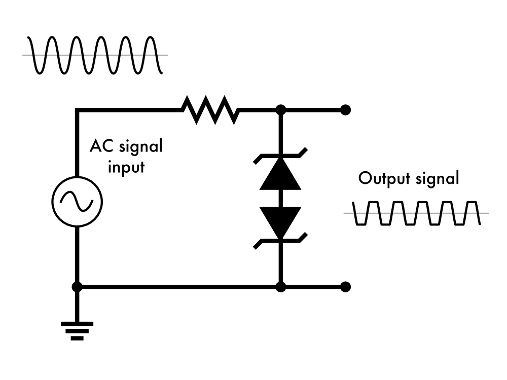
Another neat trick is to use two Zener diodes, oppositely oriented, in series. This can provide a symmetric limit on the excursion of a signal from ground, for example. This is also a common configuration for using Zener diodes as transient supressors.
Voltage translation: Easing the load on a regulator
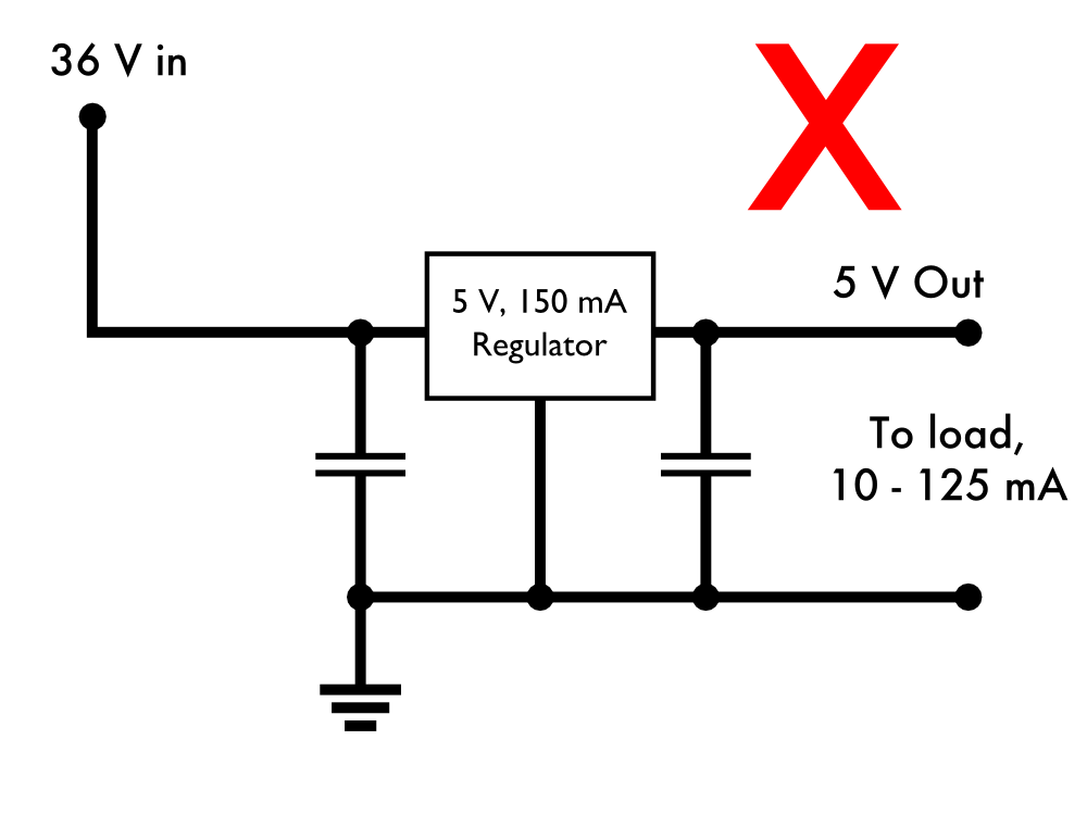
Here’s something that doesn’t work. We have a TL750L05, which is a type of 5 V output linear regulator, which can source up to 150 mA output, and its load will be variable. We need to drive it from a 36 V source. Unfortunately, the maximum input voltage of the TL750L05 is 26 V.
Let’s try adding a resistor in series to drop some of that voltage:
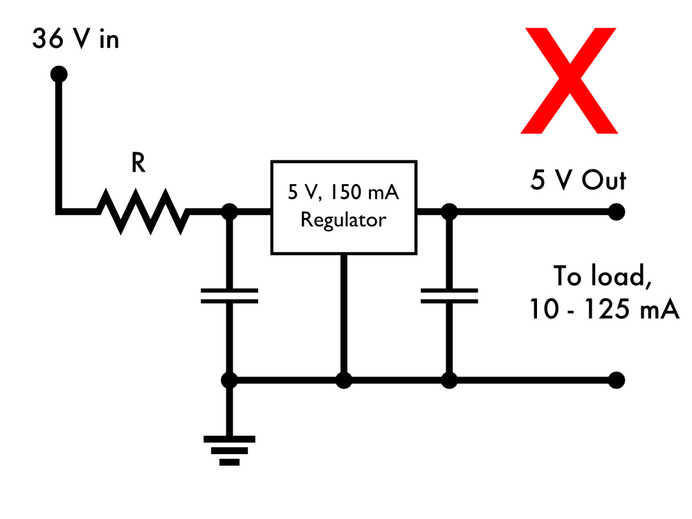
Our output load can be as high as 125 mA and as low as 10 mA. So, what value resistor will work for us?
Suppose that we assume 125 mA load. Then to take up (say) 20 V on the resistor, 20 V / .125 A = 160 Ohms. If we use 160 ohms, that will drop only 160 Ohm × 0.01 A = 1.6 V at 10 mA load, and 36 V – 1.6 V is still larger than 26 V. In order to be safe for the 10 mA load, we should pick a resistor that gives us at least an 11 V drop, for 25 V input to the regulator. So, 11 V / .01 A = 1100 Ohms would be safe for the 10 mA load. But if the load increases to 125 mA, the drop across 1100 Ohms would be V = 0.125 A × 1100 Ohms = 137 V, which means that the input to the regulator would be below 5 V, and it would cease to operate.
Clearly, there is no resistor value that you can pick that actually will work for both the low and high current cases.
Aside: We have skipped over a couple of minor details about voltage regulators that often merit consideration. First, a linear regulator always requires slightly more voltage on its input than its output. This voltage difference is called a “dropout voltage” and can be as much as 0.6 V for the TL750L05, a so-called “low dropout” regulator. This means that when outputting 5 V at 150 mA, the input terminal of the regulator needs to be at 5.6 V or greater. We can safely ignore this here, because 36 V – 137 V is still below 5.6 V.
A second minor detail is that a linear regulator actually pulls slightly more current into its input than it sources from its output. The reason for this is that some of the current that flows into the regulator’s input flows to ground through its third “ground” terminal instead of to the output terminal. This “quiescent current” can be as much as 12 mA for the TL750L05. This means that when 125 mA flows out of the regulator’s output terminal, there can be as much as 137 mA flowing into the input terminal. In the example above, this means that the maximum voltage drop across an 1100 ohm resistor would be more accurately estimated at V = 0.137 A × 1100 Ohms = 151 V. Again, this does not change our analysis.
Let’s try again, this time with our friend, the Zener diode.
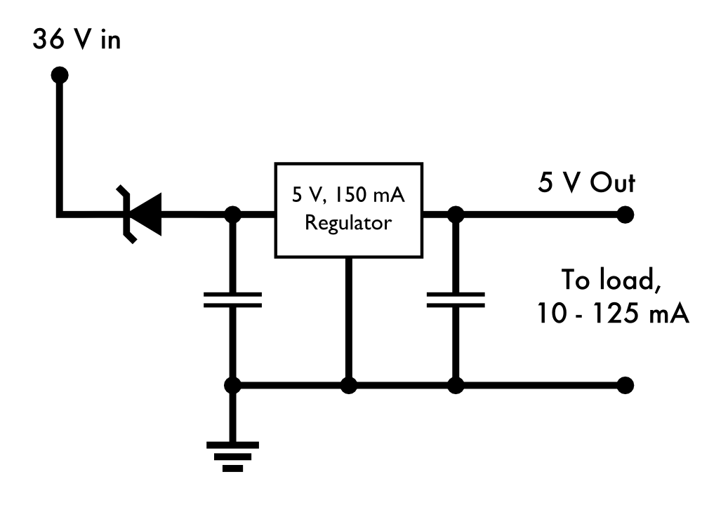
Finally, let’s try using one fat 20 V Zener diode (type 1N5357BRLG), to drop some of the load. Then, the output on the anode of the Zener is just 16 V, well within the safe input range of the regulator. The 1N5357BRLG is rated for 5 W maximum.
When the regulator operates at 125 mA output, its input current can be as much as 137 mA including quiescent current, so the power dissipated by the Zener can be as high as 20 V × 0.137 A = 2.74 W. It will get warm, but we are well in the safe operating conditions of the Zener, and now the circuit will work.
Updated April 2020 to include notes about linear regulator dropout voltage and quiescent current.
All this technical mumbo-jumbo and no mention of the most important Zener at EMSL???
http://evilmadscience.com/productsmenu/partsmenu/327-zener
I see this injustice was rectified on Google Plus.
There *is* a link there, but it it’s subtle. =^..^=
Windell H. Oskay
drwho(at)evilmadscientist.com
http://www.evilmadscientist.com/
Very cool!
I showed this article to a friend who has only a little background in electronics & she finally understands zeners.
Any plan to do more like this?
We already have a few other articles in our “Basics” series, and we do plan more.
Here is a search link to find others on our site.
Windell H. Oskay
drwho(at)evilmadscientist.com
http://www.evilmadscientist.com/
Doh!
Found it. Too subtle for me.
Alright I missed it. Would you be kind enough to point it out? Or give a hint?
Link in sentence above last diagram.
Another point, from the lessons learned the hard way file …
Below about 6V, zener diodes have a very "lazy" knee. That is, they do not have an abrupt breakdown. So, a 4.3V zener will conduct some measurable current at 4.0V. This can be a bit too much in battery operated circuits when the zener is used for OVP.
Also, a small signal NPN transistor, such as a 2N3904, will usually have 7.5V breakdown on the reverse base-emitter junction. Handy if you have no zeners in stock.
The Speaker Guy
Good things to know! Thanks!
Help!! In the last example I see a voltage regulator that will not turn on unless the voltage in is > 20VDC. Please explain…
I guess that the Zener actually consumes the 20 of the 36 volts and passes the remaining 12? I was thinking that at 20 volts it would be switch on forward the full voltage.
The input voltage is a fixed 36 V, and as the Zener diode always drops 20 V, the input to the regulator is 16 V.
Windell H. Oskay
drwho(at)evilmadscientist.com
http://www.evilmadscientist.com/
I didn’t see any mention of the negative resistance characteristics of a Zener/Avalanche diode. Under certain conditions (low reverse current), some of these things exhibit a negative resistance, and can actually form a relaxation oscillator in the correct circuit configuration. Take a look at the expanded portion of Figure 5 on Page 19 of On Semi’s “TVS/Zener Theory and Design Considerations Handbook”: http://www.onsemi.com/pub_link/Collateral/HBD854-D.PDF
Dave