


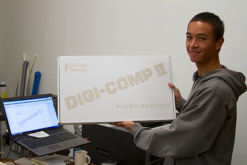
We recently announced availability of our “first edition” wooden Digi-Comp II kits. These are big kits, and there are a variety of different manufacturing steps and processes— from CNC routing to vacuum forming —that have somehow found their way into the build. In this little photo essay, we’ll show you just what goes into the making of the Digi-Comp II, First Edition.
Making the big parts
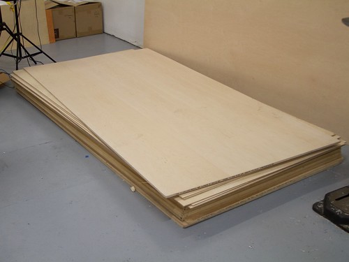
It all starts with the plywood. We begin with 4×8′ sheets of ½” thick maple-faced veneer-core all-hardwood plywood. This is high-end, dense, rigid stuff, and it isn’t cheap: it costs a little over $100 per sheet. We’ve found a world of difference between this and cheaper grades of hardwood plywood (cheaper, here still being in the neighborhood of $80/sheet), both in terms of rigidity and the quality of the inner plies.
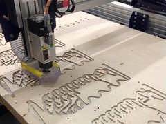
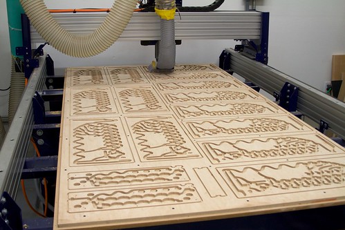
The first stage of manufacturing is one of the most time consuming: cutting out the big parts from the ½” plywood on the CNC router. Actually, that’s not exactly right; cutting out the parts is actually pretty quick, it’s carving all of the detailed features that takes such a long time.
For each Digi-Comp II, there are six pieces that are cut out on the router: the top playfield, the lower playfield along with its ramp, and the three pieces of the wooden stand. You could fit about 8 full sets into a single sheet of the plywood, but in practice it turns out to be better to nest as many as possible of a single piece type onto each sheet of wood, so as to minimize the relative time cost of tool changes.
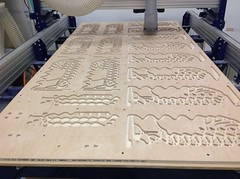
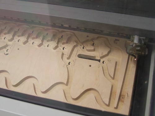
The top playfield is by far the most complex to make, because of the number of different features and feature sizes involved. The main “channels” where the balls roll are carved with a specialized wood-cutting ½” diameter endmill, in two passes. The first pass cuts 0.325″ deep, to rough-out the channels. After the first pass, we cut the 0.070″ diameter holes for the flip flops and switch pivots, and then the 1/8″ slot arcs that limit the movement of the flip flops and switches. All in all, there are 33 pivot holes, and 33 arc slots in the top playfield, along with 15 other larger holes that connect the upper and lower playfields.
After these inner cuts, we run the second pass with the ½” diameter tool, going slightly deeper. This brings the channels to their final depth (approx. 0.340″), but more importantly, it produces a flat surface at that depth: it removes any stray burrs or “fuzz” remaining on the inner holes and slots after the previous operations. This smooth, flat finish is what will allow the flip flops to slide freely on these inner surfaces at the bottoms of the channels.
A tricky part of this second pass is making sure that it cuts and exposes a single ply of the wood. Since the individual plywood layers are typically below 0.050″ in thickness, this requires some effort to ensure that the sheets of wood are held down reasonably flat. Even so, not every piece of wood is perfect: Occasionally, a giant knot appears just as you reach down to that final ply.

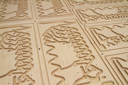
Finally, we use a ¼” router bit to cut out the parts. We don’t actually fully cut out the pieces, but instead leave them “tabbed in” to the sheet by little bridges, so that they are always held in place while the router is cutting. After the router stops, we manually cut those bridges, leaving us with our big pile of CNC routed parts.
The total CNC cutting time elapsed per kit is roughly 35-40 minutes. There are a few ways that this can be sped up, but each of them involves making tradeoffs between time and cut quality. Doing it well in wood takes time. A better choice, of course, is to not individually carve every single Digi-Comp II— precisely why we’re planning to use different fabrication technology for our future kits.
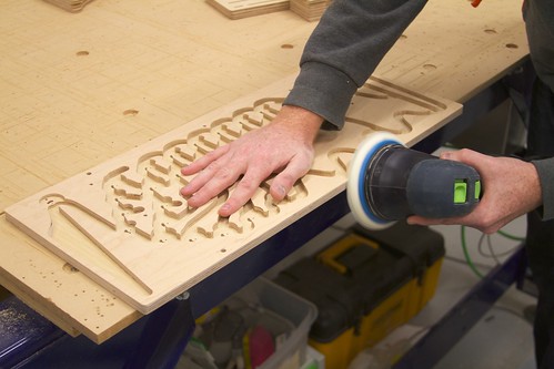
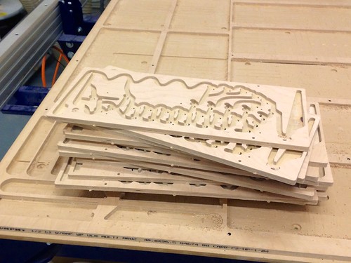
And, as the last real “woodworking” step, all six of the CNC-cut parts are sanded on all of their sides. First, with a coarse grit to remove the tabs, and then with a fine (320 or 400 grit) sandpaper to smooth the sides and corners, to make them finger-friendly everywhere that you might grip it.
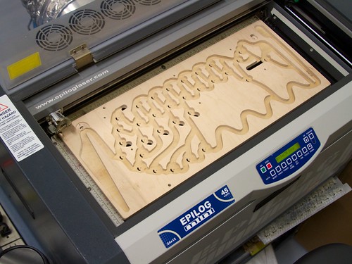
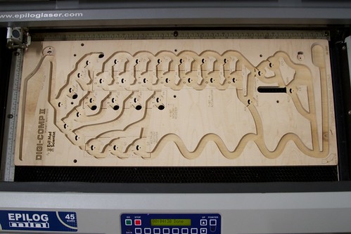
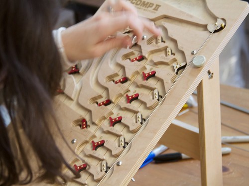
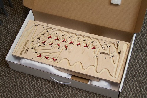
After sanding, the markings are added to the top playfield by laser engraving.
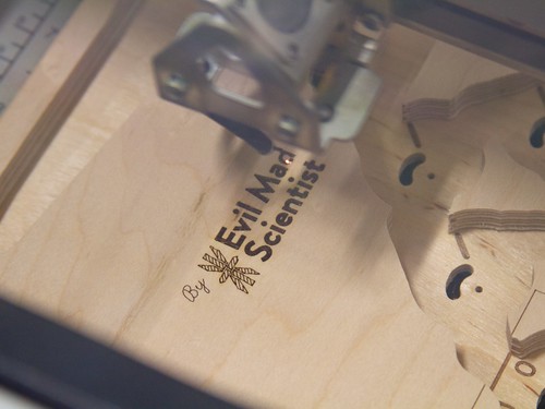
The laser markings are used to label all of the flip flops and switches, as well as to add the branding, serial number, and markings for the default flip-flop and switch positions.
The laser is focused at the level of the very top surface of the playfield, so that the markings at the top (like where it says “Evil Mad Scientist” in the picture above) are fine and sharp, but the markings in the channels are slightly defocused, making them more bold than sharp, which turns out to improve readability in the channels.
Making the little parts
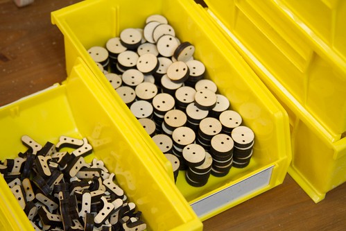
While the big CNC parts may get all the glory, there are also a total of 85 mostly-tiny laser-cut parts in each Digi-Comp II.
Most of these parts are the wooden flip flops and switches that poke through the top deck of the Digi-Comp II. On the top side there are 15 flip flops and 16 switches. On the bottom side, there are 7 half-flip-flops underneath and connected to the 7 accumulator flip flops, and 6 flip flops underneath and connected to the 6 accumulator mode switches. The remaining 18 topside flip-flops and switches (that do not have any bottom-side function) wear a circular wooden shoe— a “clog” —on the reverse side of the top playfield.
The remaining laser cut parts comprise the start lever, ball release, and Delrin washers and spacers that provide the correct vertical spacing to the bottom-side components.
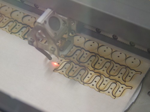
The flip flops, switches, and clogs are laser cut from ¼” plywood of a similar grade to that which we use for the CNC router cut parts. Before cutting, we mask each piece of plywood on both sides with “application tape,” which is just 12″ wide masking tape on a huge roll, to protect the surfaces from excess laser smoke and debris. After cutting, we remove the now-tiny pieces of tape from each little piece, stain the ones that will be the red parts, and sand the ones that need to turn smoothly.
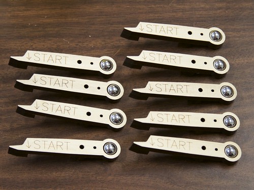
The start lever is cut from ¼” poplar, and has an “extra” pachinko ball in its tail as a counterweight. It actually consists of three pieces, glued together, to give the necessary 3D shape, where it’s ½” thick at the pointy end, where it is pulled down when a ball lands on the end.
As this piece ended up thicker, we tried a number of prototypes where the start lever was instead cut on the CNC router. However for these relatively tiny parts, it turns out to be faster and more reliable to laser and glue it than to CNC route and sand.
Assembly and Testing
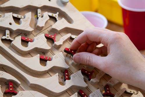
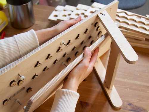
The pivot pins for the flip-flops, switches, start lever, and ball release are all domed-head brass rivets or finishing nails. The pins are placed through the flip flops, and those little assemblies are slid into their slots in the playfield.
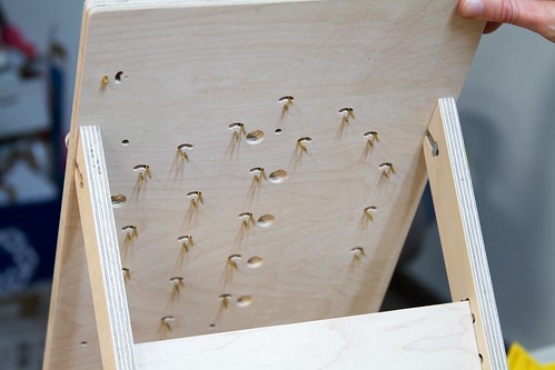
This is the bottom side of the top playfield, with all of the top parts inserted, but none of the bottom-side flip-flops, switches, or clogs installed yet. Note that we’ve glued together and bolted on the 3-piece wooden stand, so that we can rest it on its side to add those bottom parts.
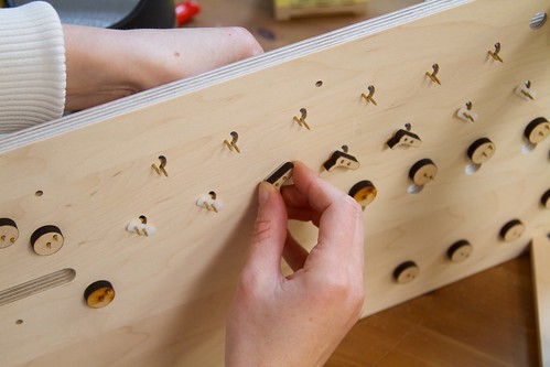
Here, we’re attaching the half flip-flops to the bottom side of the accumulator flip-flops. (Aside: These are part of the CLEAR operation circuit; if a given bit in the accumulator is a 1, a ball rolling by on the bottom will flip it to 0, but if it is already 0, it will be left alone.)
In the photo above, you can see some of the white Delrin spacers used to put the bottom-side half flip-flops at the right position, as well as the circular wooden clogs for retaining components that do not have any bottom-side function.
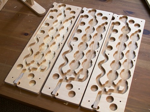
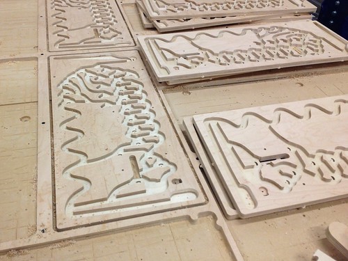
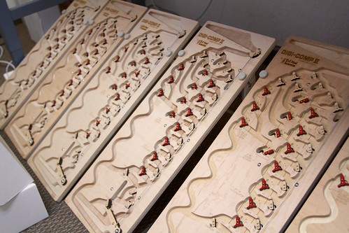
The lower playfields (three of which are shown here) do not have any active components on them, just channels to guide the rolling balls past the components mounted to the top playfield.
The three channels on each board guide the ball below the memory switches (left channel), the accumulator flip-flops (center channel), and accumulator-mode switches (right channel). All three channels guide the ball to the ramp on the bottom, which is the “sixth” CNC-router cut part. The ramp, cut from ½” plywood, guides the ball back to the upper playfield after bottom-side operations are complete. The bottom-side channels are intentionally wiggly in order to slow down the ball as it rolls, so that it does not fly out of the ball return with excessive velocity. In some of our prototypes without these features, flying pachinko balls were a serious problem!
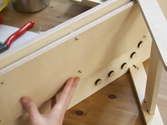
The bottom playfield is attached to the upper playfield with six long 8-32 screws, nylon spacers, and wingnuts on the bottom side. The nylon spacers ensure consistent spacing between the two decks, and clamping it at six positions (rather than two or four) keeps the two decks nicely parallel.
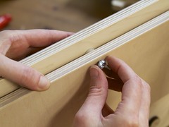
Finally, the start lever and actuator wire are added, and we can begin testing. To ensure consistent operation, every operation is tested a few dozen times. Once everything is working reliably, the lower playfield is removed, and a dab of wood glue is added to each bottom-side flip-flop, switch, and clog, to make sure that they don’t accidentally come loose during shipping or so forth. The wood glue is relatively non-permanent; the parts can be pulled apart and more glue added later if need be.
Packaging
After testing, it’s finally time to think about sending along the Digi-Comp II’s to their new homes. But, we need to make a couple of little detours along the way.
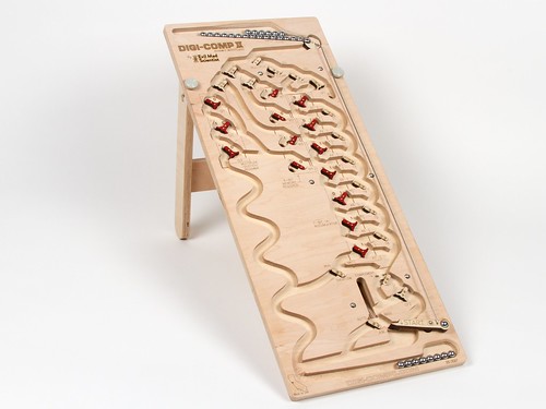
The Digi-Comp II, First Edition is pretty big, at 24×10″, and 12 ½” tall, when mounted to its stand. With the stand removed and set beneath the playfields, it’s more compact, but still nearly three inches tall, and strangely shaped. While there are plenty of boxes that will contain that outline, we also need to make sure that the Digi-Comp will be safely cradled within its box so that it can survive shipment.
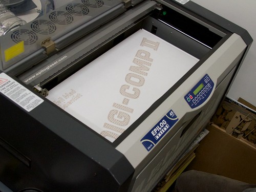
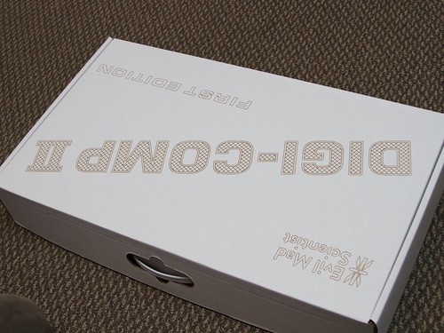
First, the box. We found a nice 24×14×4″ white cardboard box complete with a “carrying case” style handle. While we had originally planned to silkscreen these boxes, we somewhat jokingly thought to check, and it turns out that the boxes actually fit in the laser… barely.
After working at it for a while, we found that using the same defocused technique that we used for engraving the lower channels on the playfield, we were able to make dark, broad marks on the boxes, which look a lot like they were drawn upon with a permanent marker. There’s a happy medium in between too light of a color, and so dark that it leaves char that smears easily.
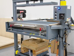
Next, there’s that matter of safely cradling the Digi-Comp II within the box for shipping. Fortunately, we have just the thing:

This is an industrial vacuum former, a tool that we may use in the future to make the actual playfields of future Digi-Comp II models. But for the First Edition, we’re just using it to make a polystyrene cradle, or “box insert” to hold it in place during shipping.
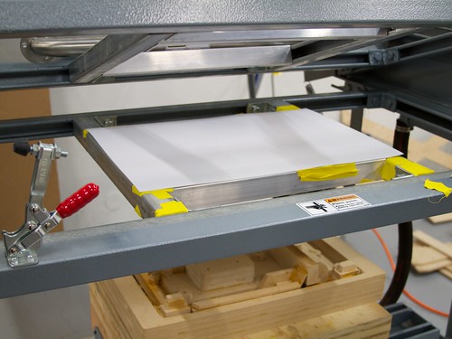
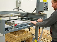
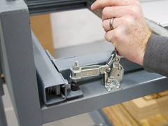
We begin with a 14×20″ sheet of 1/32″ high-impact styrene plastic, and clamp it into the frame.
Then, we pull slide the heater— essentially an electric oven putting 10 kW of power into making heat —over the plastic in the frame, for about 90 s.

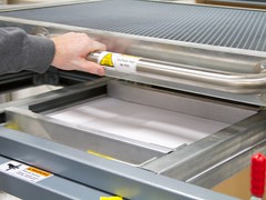
After the plastic softens, we slide back the heater, and raise up the vacuum-forming mold (or “buck”) to contact the surface of the plastic, and turn on the vacuum, which pulls the soft plastic down into the mold.
One minute later, the plastic is cool enough that we can unclamp it, and remove it from the machine. Here is what it looks like:
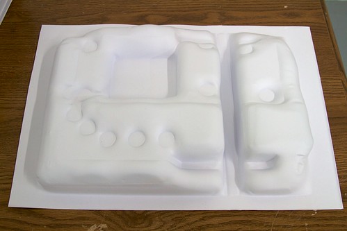
It’s kind of a rigid plastic “puffy pillow” with a few key indexing features that will constrain the Digi-Comp. It is, however, nothing to look at. (If we continue making box inserts this way in the future, we plan to make a new mold, using lessons learned from this one.)

The insert is cut along the groove, and placed into the two ends of the box, held in place with industrial double-sided adhesive.
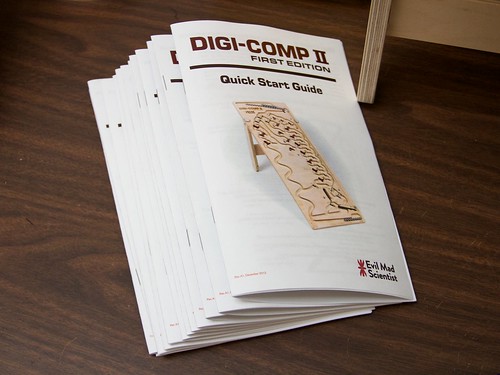

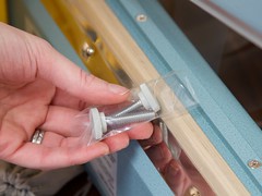
There are two other things that go in the box: A little velvet drawstring pouch, containing the pachinko balls (pre-sealed into little 35-ball units) and the two thumbscrews for attaching the stand, and the Digi-Comp II, First Edition Quick Start Guide.
(You can download the quick start guide right here, a 4 MB PDF document.)
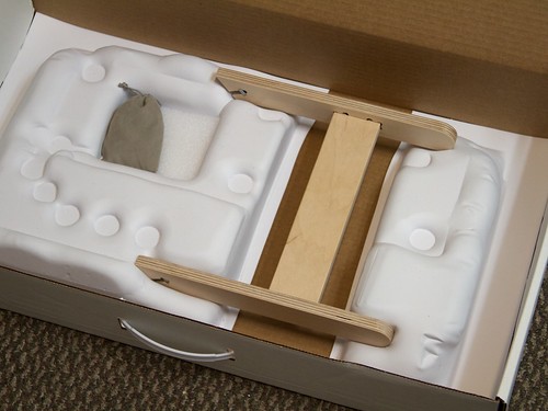
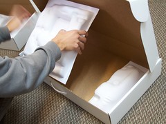
The pouch goes in the pocket on the left, and the stand fits (only one way) into indentations in the two halves of the box insert. The rest of the features are there to cradle the lower playfield, and prevent it from sliding.
And, finally, at last, into the box it goes. The top lid of the box has two foam blocks that press down onto the top playfield when it closes, so that it’s held vertically against the vacuum-formed box insert.
And so when the box is closed, and you turn it side to side, all that you hear is a myriad of soft little clicks, as the little flip flops flip from zero to one and back.

When’s the official air date on “How It’s Made”? :D
Very cool :) It’s one thing to know that Digi-Comp it’s CNC’d and laser-cut, but knowing the actual production algorithm (including packaging) is much more telling and educating.
Apparently I should not post so early in the morning, sorry.
This is awesome, will it be open-sourced? We’d love to use our open-source CNC and members Epilog to do this! Your a partially open-source company right? I’m forgetting now.
Most of our products are Open Source Hardware kits, and we are generally open to sharing our designs. In many cases (like for most of our electronic kits), it’s usually straightforward to just release the original design files– that we made for our own use –and have a reasonable expectation that people could follow those designs to reproduce and fork the design on their own.
However, this particular design is not really like that. We do not have a self-contained set of design files that really captures “how to build it,” as we would for electronics. There is so much know-how in the exact materials, processes, tooling choices, and so forth that designing a set of reliable plans for building it from scratch would actually be a big project. And so it’s a tough call. We have learned from experience that it is generally counterproductive to release a set of “half baked” designs that end up frustrating people who try to follow them. So, while we wouldn’t rule out an open source release, it is unfortunately not trivial either.
Using a synthetic material like Corian, instead of the super high-grade plywood might be a lower cost option for a future edition (and no knots to contend with!). You might not even have to change your manufacturing process!
While Corian machines beautifully— I’ve had the opportunity to machine it –it actually costs several times as much as our plywood, and probably wouldn’t cut down on the machining time. If we could figure out a good alternative to laser marking for putting labels on it, it could potentially be a beautiful high-end version.
Another thought that occured to me was casting the main components. This has the advantage of having very little waste, and being pretty fast, but obviously setup is more complex.
One advantage of Corian is that it wouldn’t be subject to changes in humidity. I think it would probably also operate more smoothly.
This level of product design and execution is fantastic. Thanks for sharing your process!
Just some thoughts: You probably have already considered them:
Making the large channels in two passes is wise. However, since the cuts are different, if you have the extra chuck, using two different tools is also wise. First, because the tool that makes the first cut has no finish requirements, and will continue to do its job even if it is wearing/dulling. Second because the tool that makes the second cut has less load but must maintain the best possible finish.
(overly wordy discussion follows) The pass that takes off the last .015″ will not be seeing the same loads as the first cut: Depending on whether the first cut takes out the majority of the fifth layer of glue or not, the second-pass tool will be seeing mostly the edge of the glue at the ‘sides’ of the cut, rather than having to cut it across the whole leading hemisphere of the ball end. Glue is harder on the tool than the wood between, so you can move the tool more quickly if it is cutting mostly wood.
That means the second-cut tool can be run at a different rotation speed (or could well have a different number of flutes (edges) depending on what’s available) because the chip load will be quite different. As your CNC operator/programmer and tool supplier knows, the life of a tool is dependent on many parameters, but most important is the size of the chip: If you try to cut too large a chip, you wear out the tool faster and can weaken or break it from the torque; if the chip is too small, it doesn’t take the heat of the cut away with it, but stays in contact with the tool, shortening the life of the edge and eventually the tool. Dust is pernicious: it adheres to the tool and stays in the cut around the foot of the tool, unless the chip is large enough that it stays together and is ejected behind the tool. Making the finish cut at the same speed/rotation rate as the ‘hogging out’ cut should be making a lot of dust. If your 1/2″ tool is going dull too quickly, look to the chipload calculations.
(end of wordy discussion)
You can cut those boards apart more quickly with a 3/4″ tool, and there’s plenty of room between the parts the way they are nested. This also leaves less material in the spider (what’s left after the parts are removed) to have to drag off somewhere for disposal, and contributes to the vacuum system bags. (I presume you are recycling the contents of those, either to some industry that processes and recycles, or to a local farmer for bedding.)
It looks like you’re chipping inner layers at sharp corners, as well. This can be problematical for any CNC cuts of flatstock: generally, I found that it was better to cut into a corner than out of it. If the flukes, as they rotate, are cutting the point first and then into the material ‘behind’ the point, they will compress the edges of the inner layers into the remaining wood rather than pulling it out. In solid wood, you have all the grain moving together: in plywood, the grain is usually laid at different angles for each layer. If you’re cutting ‘out’ of the point, those layers whose grain lies crossways to the direction of cut can be pulled out, while the ones lying in the direction to the point tend not to. So with plywood, always arrange the order of cuts so that the final cut that defines a point or vertical sharp edge cuts into and past the point, rather than out of the wood which supports the point. (Hard to describe without a picture. Draw a V. Draw an arrow on the left side with the head (point) down. This cut, taken from solid stock, defines one side of the sharp vertical edge. With clockwise rotation (seen from above) it makes a clean, fast cut. Draw a second arrow on the right side of the V with the point up. Again, with clockwise rotation (seen from your vantage) this makes the fastest cut, taking the largest chip. The edges of the flukes on the tool cut into the material that remains, so when it gets to the corner, the fluke edges are pushing the point material rather than pulling it out. If I were designing the cut, I think I’d experiment a bit with some scrap or maybe the leg-spacer area to see if the tool and rotation speed I can do will work better cutting the second side of the feature from un-precut area, or if it is cleaner if I take off all but the last 1/8″ first, and then make the finishing cut: It is not true that the less you cut, the less likely you are to chip the corner.)
I used to use a program which was an add-on to AutoCAD to program my cuts. It was good because I could control the direction and tool speed for every cut, if I was willing to put in the effort. Output was to G-code, which isn’t as hard to learn to read as C++ and can be edited with any text editor. There were times when I had to edit G-code to get the results I wanted. It was always worth it!
Although we did gloss over some details, we are using different 1/2″ tools for the roughing and finishing passes. A compression-spiral chipbreaker-finisher for the first pass, which operates remarkably quietly and smoothly with a 0.020 – 0.025 chipload. The second 1/2″ pass is with a straight-flute solid carbide tool, running with a much lower chipload. Either of these tools can be run with a faster cut speed (at the same chip load), but we’ve found the cut quality to degrade as we do so, with increased tearing out and chipping.
I’d love to be able to cut out the parts with the 1/2″ tool– for quickness and quietness –but there isn’t actually room between them to do so, unless we want to cut fewer parts per sheet.
Hah! I recognize that sander. Festool makes some really awesome woodworking tools. Thanks for sharing! :-)
-=- Terence