


Barbot 2011, the cocktail robotics exhibition, is happening on Friday and Saturday nights this weekend– April 1 and 2 –in San Francisco. If you haven’t been to one of these events (and you happen to like both cocktails and robots), let me tell you: you are missing out.
Last year we built the aptly named Drink Making Unit for the event. The Drink Making Unit used three –ahem– food-safe pumps to craft white russians, and was quite a hit at the show– especially amongst people who recognized the pumps.
This year, we’ve designed a brand new bartending machine, Drink Making Unit 2.0, which we are pleased to unveil today, and unleash upon the world this weekend.
Aside from the once-again-apt-but-not-very-descriptive name, Drink Making Unit 2.0 has very little in common with last year’s machine. The mechanism is all new, and features elements borrowed from sources as diverse as pet stores, chemistry labs, and Japanese gardens. It dispenses any six fluids (up from three), in metered and selectable quantities, and also sports an all-new extra-snazzy control panel.First stop: the chemistry lab
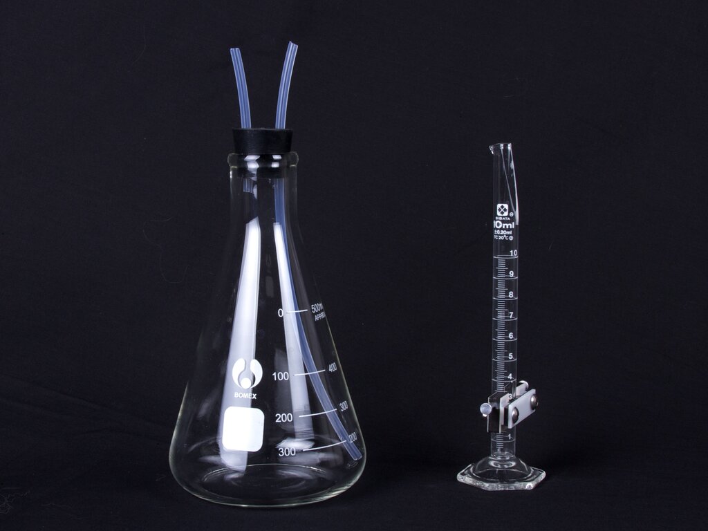
The starting point for our machine is some classic laboratory glassware: A 500 ml flask and a 10 ml graduated cylinder.
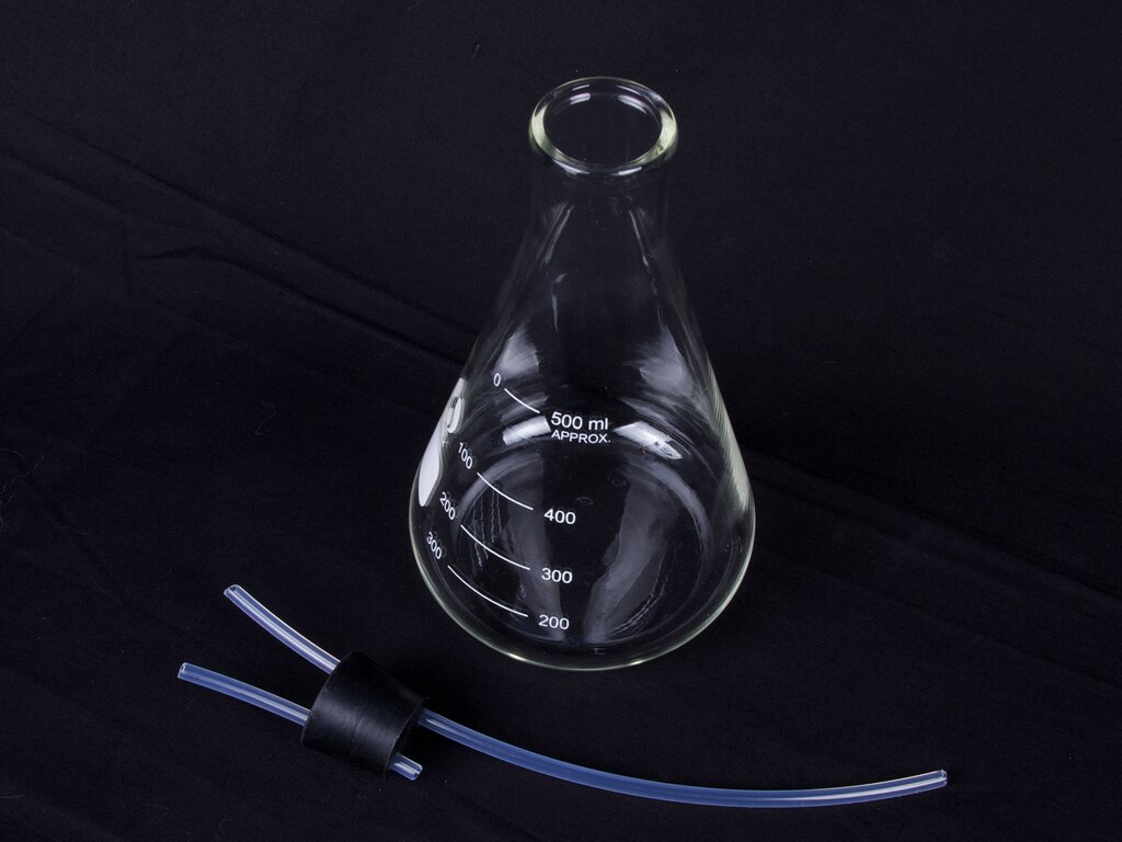
Provided that the air source is clean, this is a good and food-safe method of pumping liquid out of our flasks. However, we’re not done yet. The rate that fluid is pumped out will depend on the air pressure, fluid depth, air resistance in the path from the air pump to the flask, and so on. Accordingly, there’s no good way to be sure how much liquid we’ve pumped out, without some way of measuring. And, that is where the graduated cylinders come in.
Deer chasers, not beer chasers
There are any number of possible ways to measure the flow rate of our cocktail components, either directly (paddle-wheel flowmeter, ultrasonic, laser…) and indirectly (monitor the weight of the glass as it changes, laser interruption by liquid level, position of a float in the tank,…). However, we decided to take a different approach and
borrowed a classic mechanism from Japanese gardens: The deer chaser.
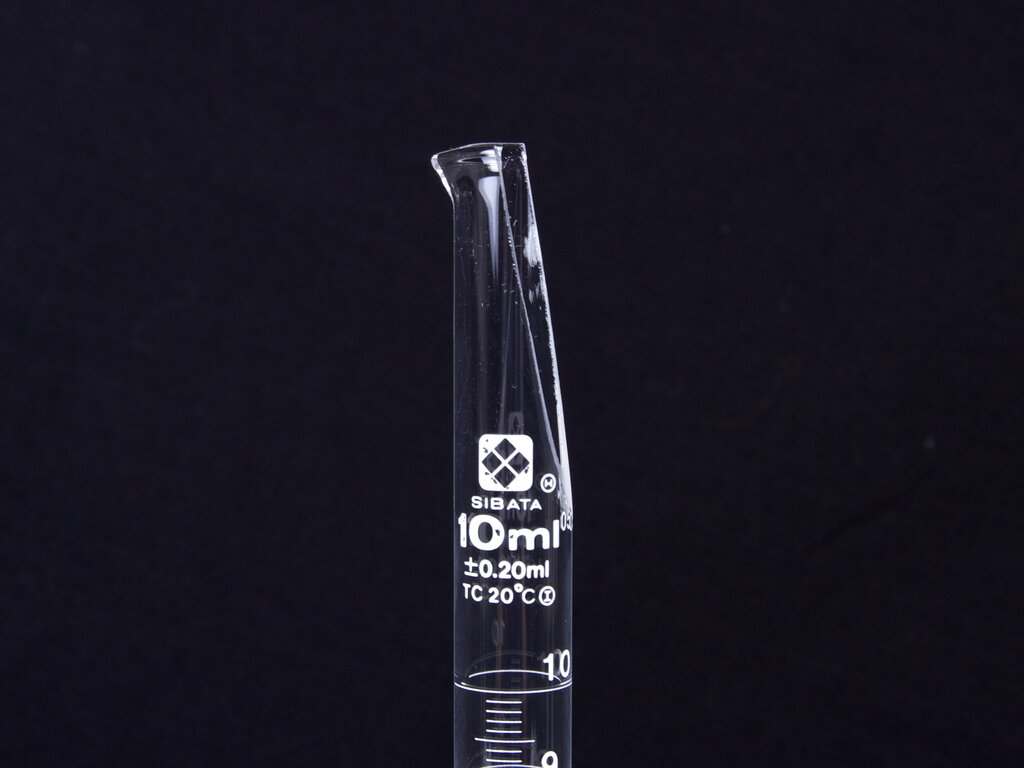 In our implementation, the tube that tips is actually the 10 ml graduated cylinder, suitably modified and mounted. The main challenge is to create an angled opening of the tube end, like the ones normally seen on bamboo deer chasers. The angled end makes it so that you can easily pour in liquid, even when the tube is at an angle, and also assists with gracefully decanting the contents once full.
Our graduated cylinders are made of glass, but cutting them is possible with a thin diamond saw blade, along with steady hands, and plenty of patience. (There are plastic graduated cylinders available, but the heft, sound, and appearance of real glass can’t be beat.)
In our implementation, the tube that tips is actually the 10 ml graduated cylinder, suitably modified and mounted. The main challenge is to create an angled opening of the tube end, like the ones normally seen on bamboo deer chasers. The angled end makes it so that you can easily pour in liquid, even when the tube is at an angle, and also assists with gracefully decanting the contents once full.
Our graduated cylinders are made of glass, but cutting them is possible with a thin diamond saw blade, along with steady hands, and plenty of patience. (There are plastic graduated cylinders available, but the heft, sound, and appearance of real glass can’t be beat.)
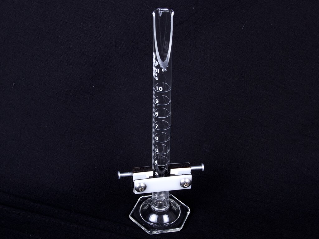 Next, we need to grip the graduated cylinder and allow it to pivot. We used a commercial 1/2″ plastic pipe to actually hold the cylinder, and bolted that to a laser-cut Delrin backing. The pivot pins themselves are 1/8″ diameter plain aluminum rivets– just like small nails without a point on the end, and are held in place with strong epoxy.
Mounting the cylinders such that they are free to pivot but not too free proved to be a challenge.
If there is too much friction in the mount (as we had in our first try with a steel shaft in a bronze bushing), the cylinder might not tip, or if it did, it might not tip back. If there is too little friction (as we had in our second try, with an aluminum shaft resting in an acrylic vee), the cylinder tends to tip too quickly. The biggest problem in that case is that once full, the cylinder would empty only part way before tipping upright again, saying perpetually in the state of 1/2 to 3/4 full– never approaching full or empty. When the level of friction is correct, as we achieved (finally!) with aluminum shafts in a plywood vee, the cylinder empties all the way before tipping back to the original position. It’s also important to position the pivot axis such that it is in line with (not significantly above or below) the center of the cylinder. If this is not the case, the tube position may be truly bistable– it may stay in the new position once it tips.Putting it all together
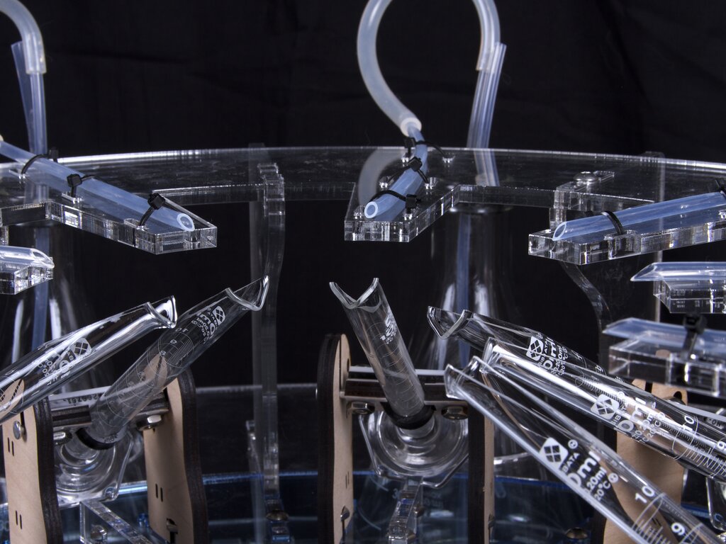
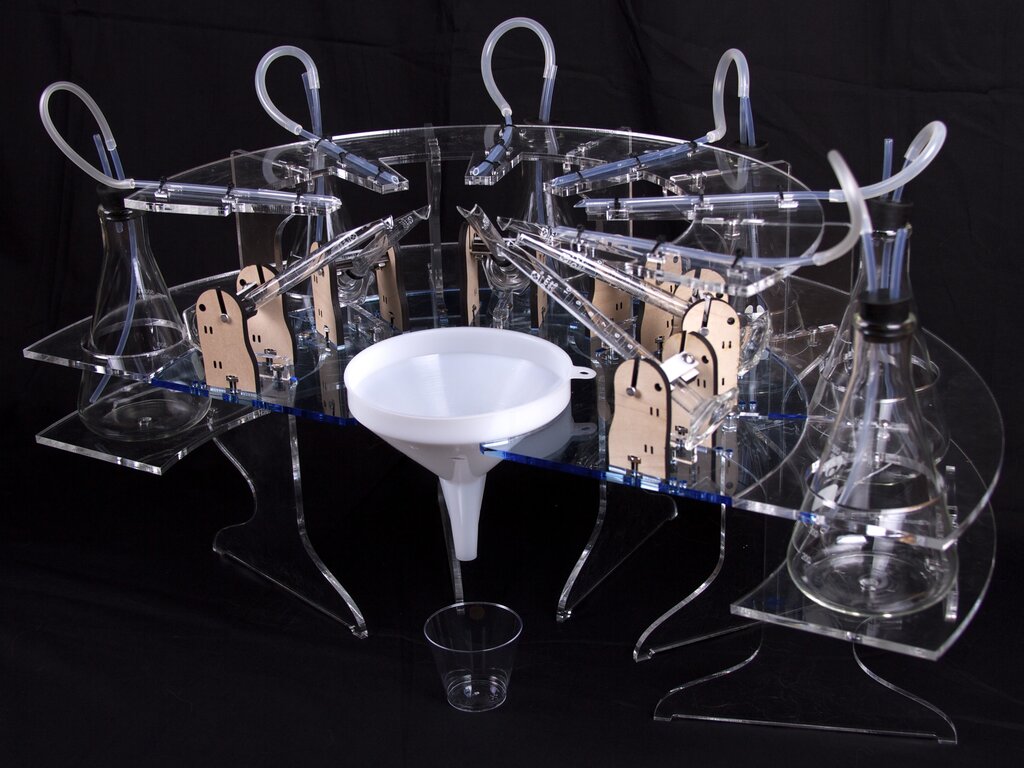
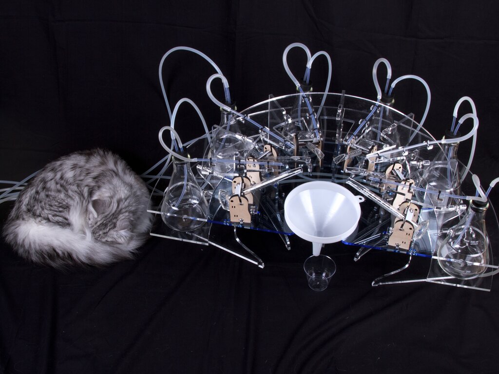
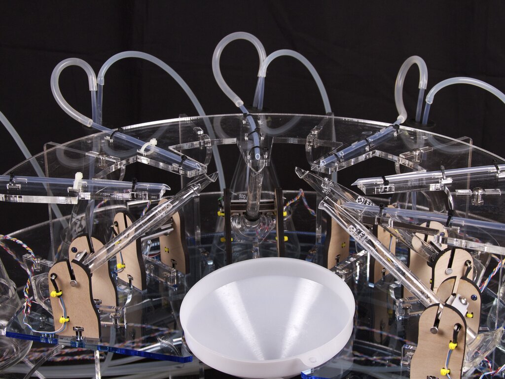
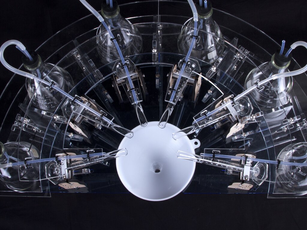 When the cylinders tip, they need something to tip into. We arranged them in a semicircle, each tipping into a wide-mouth funnel.
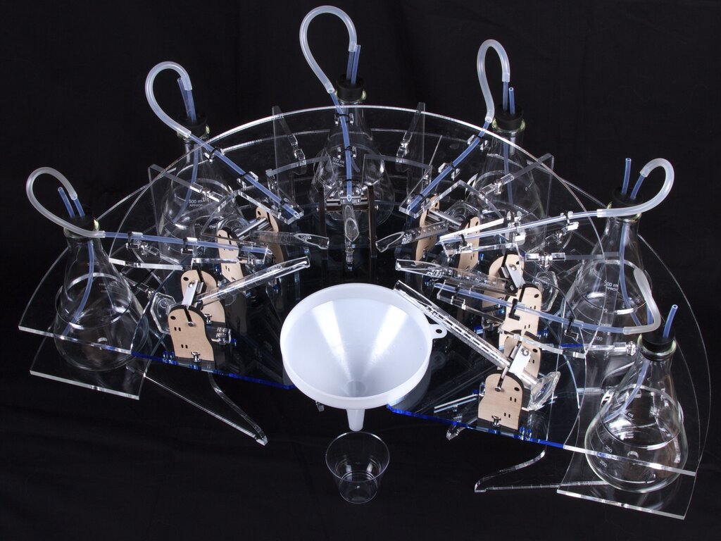 And, from the funnel, the fluids that are dispensed drip downward, into the cocktail glass.
The controller
To pump fluids from the six flasks into the six graduated cylinders, we need to selectively pump air into the flasks. We also need to be able to detect when the cylinders tip up, so that we stop pumping. And, it’s a good idea to have some sort of interface to select exactly which fluids will be pumped and in what quantities.
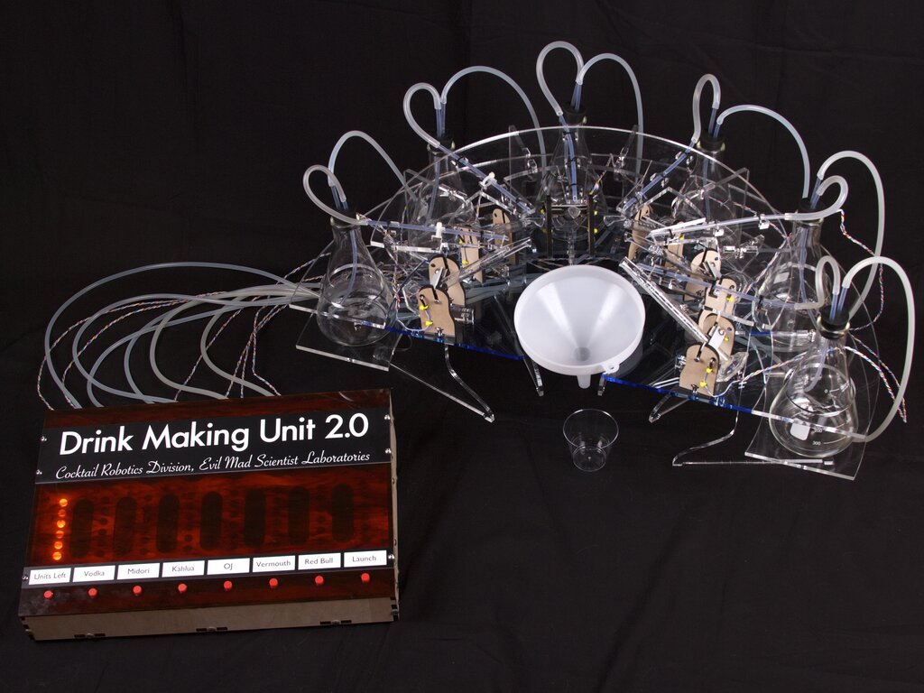
Our controller, pictured below, sitting next to the barbot, features an AVR microcontroller, eight pushbuttons, and a 6×8 LED bar graph display, all hidden beneath a tortoiseshell-plastic lid.
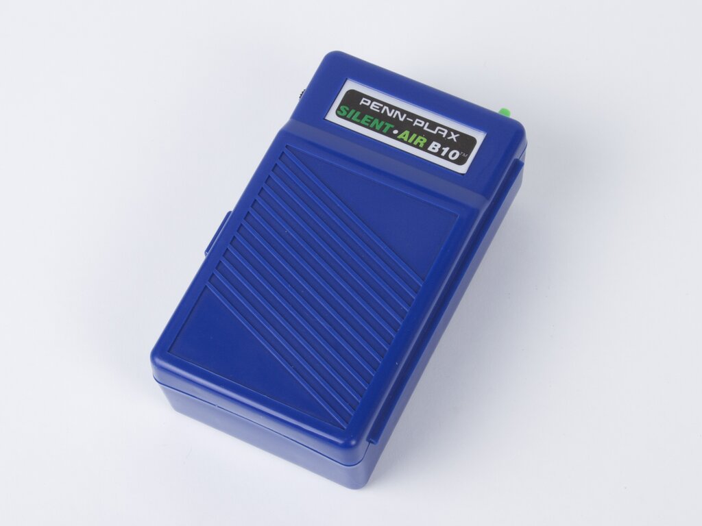
One of the challenges for the controller box is to manage the air flow to the six flasks. Two obvious strategies would be to use an air pump followed by six solenoid valves, or to use six separate air pumps.
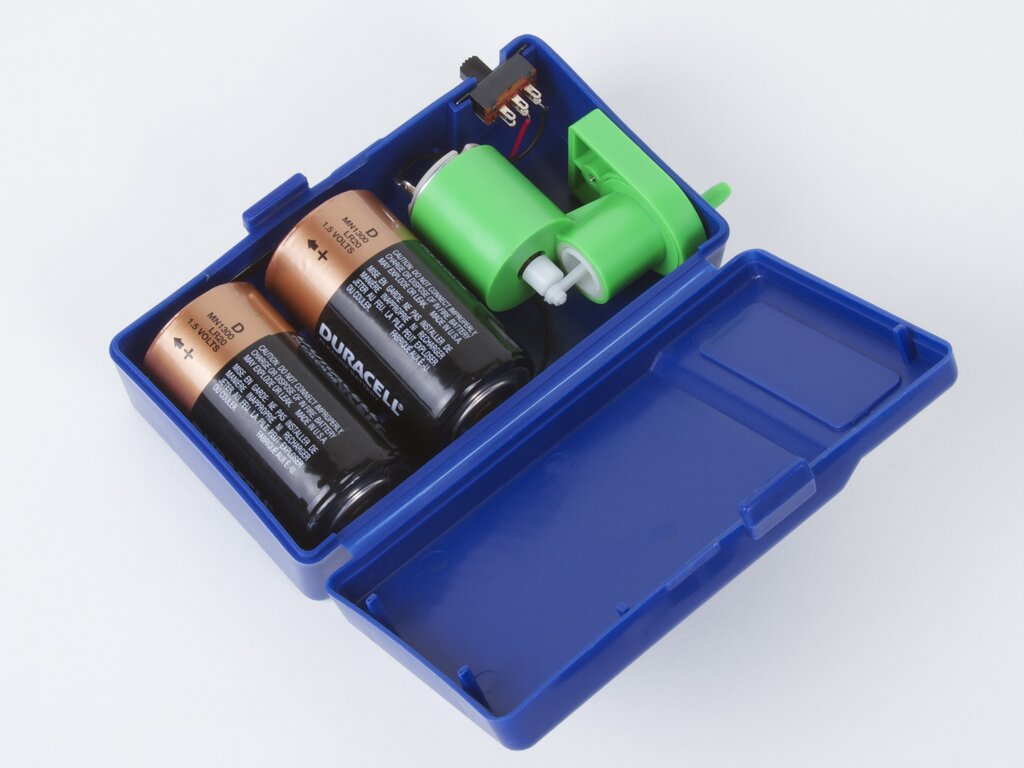
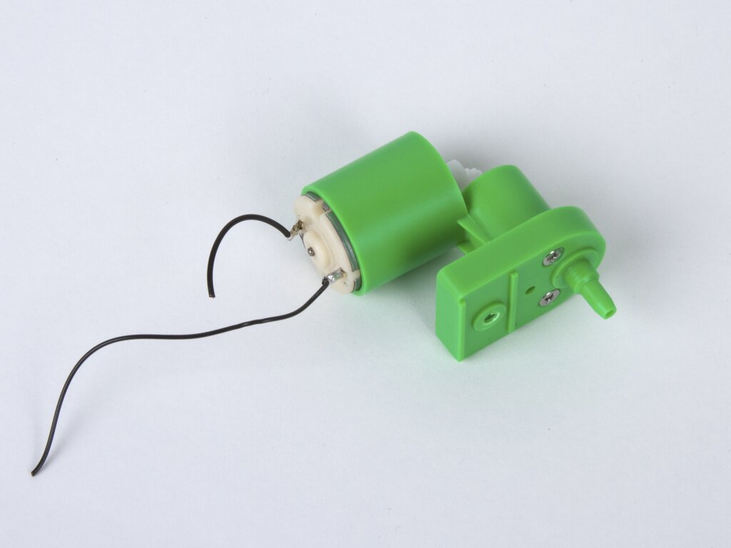 The pump mechanism is self-contained, and comes out with either zero or one screws, depending on the particular version of the pump.
Aside: There are a couple of different mechanisms in our set of pumps. This particular one has a piston mechanism, driven by the DC motor, some of others had a diaphragm.
Second aside: Once you’ve removed the pump mechanism from the case, you’ve got a very nice project box complete with a battery holder and power switch!
The pump mechanism is self-contained, and comes out with either zero or one screws, depending on the particular version of the pump.
Aside: There are a couple of different mechanisms in our set of pumps. This particular one has a piston mechanism, driven by the DC motor, some of others had a diaphragm.
Second aside: Once you’ve removed the pump mechanism from the case, you’ve got a very nice project box complete with a battery holder and power switch!
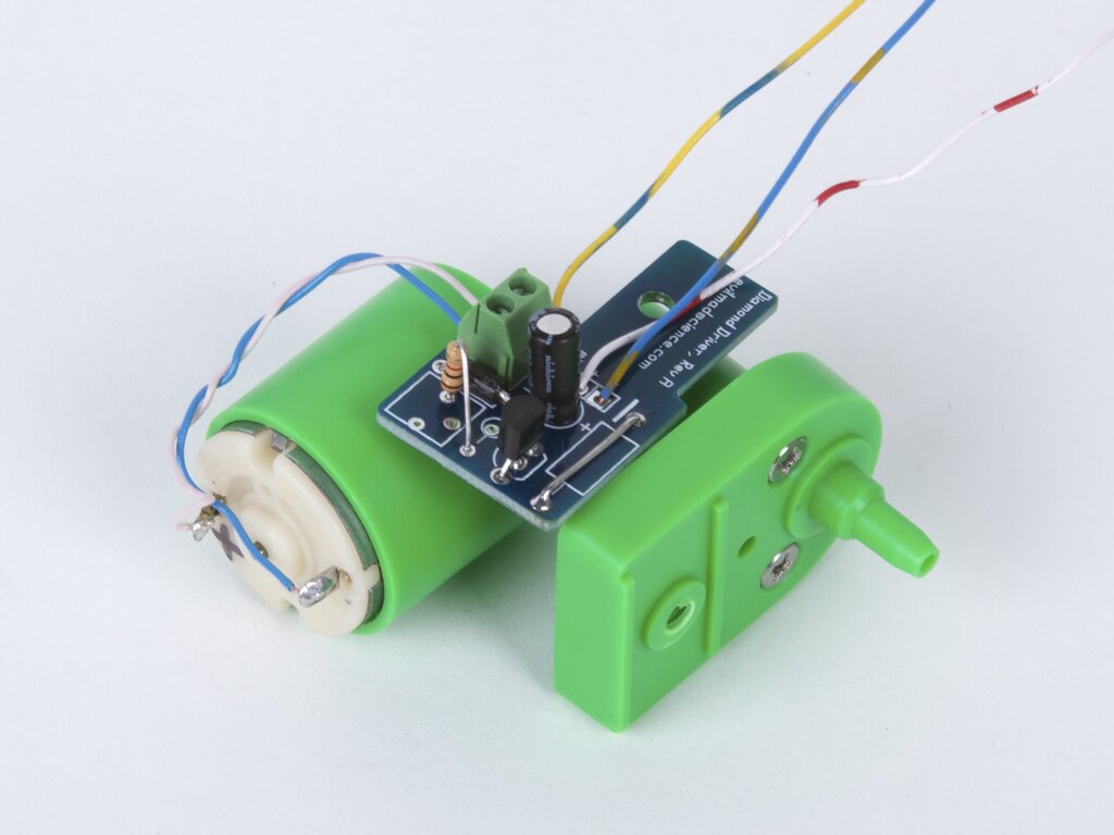
To provide a microcontroller-friendly control input for each motor, we used simple motor driver, consisting mainly of of a 2N4401 transistor with a flyback diode.
We likely would have hand-wired the components, except that we happened to have on hand a pile of tiny circuit boards already implementing that circuit. (And before anyone asks: it’s the circuit board from the forthcoming Egg-Bot kit diamond engraver attachment.) To make up for the voltage drop in the transistor (the saturation voltage) we ended up actually running the motor drivers from 3 V (two D-cells in series), with a reduced duty cycle.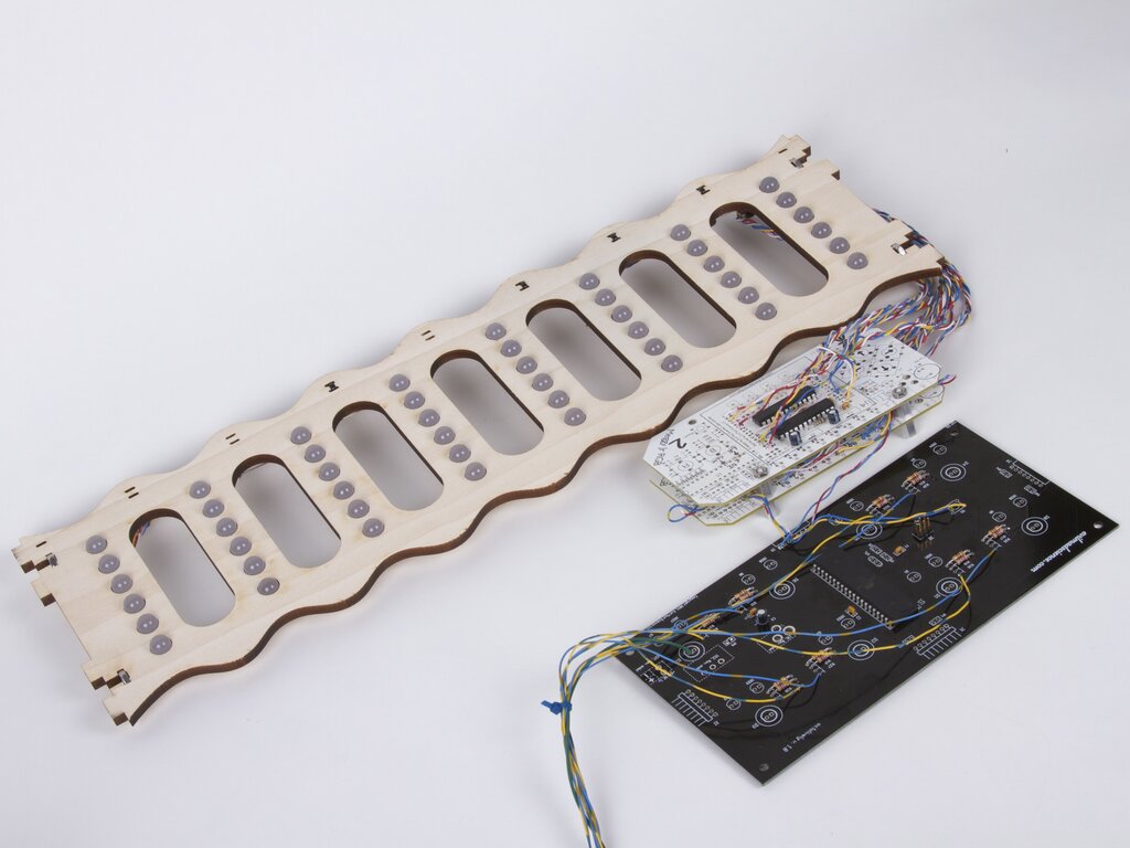 The microcontroller in the circuit is an ATmega164P, a 40-pin AVR, located in the middle of the big black breakout board. The six air pumps are controlled by six of its outputs.
We also wired up a big LED display– 48 LEDs in an 8×6 grid. We used 10 mm diffused-lens, warm-white candle-flicker LEDs for an unusual old-timey look– something like a cross between neon and jittery incandescent.
The microcontroller in the circuit is an ATmega164P, a 40-pin AVR, located in the middle of the big black breakout board. The six air pumps are controlled by six of its outputs.
We also wired up a big LED display– 48 LEDs in an 8×6 grid. We used 10 mm diffused-lens, warm-white candle-flicker LEDs for an unusual old-timey look– something like a cross between neon and jittery incandescent.
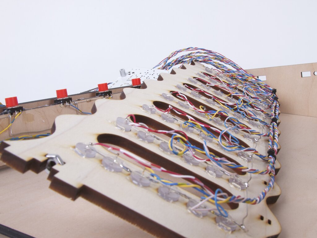 Here’s what the back of the LED matrix looks like: Lots of wires (one for each LED) and hot glue to mount them in the holes.
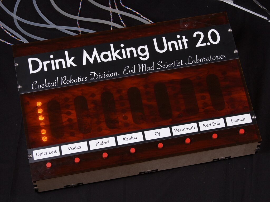
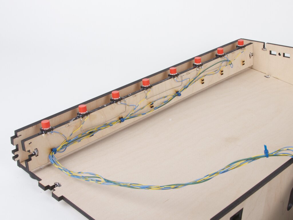 Drink Making Unit 2.0 is controlled by eight tactile button switches– one “reset” on the left, a “go” button on the right, and six in the middle for configuring quantities. Each goes to one input on the AVR.
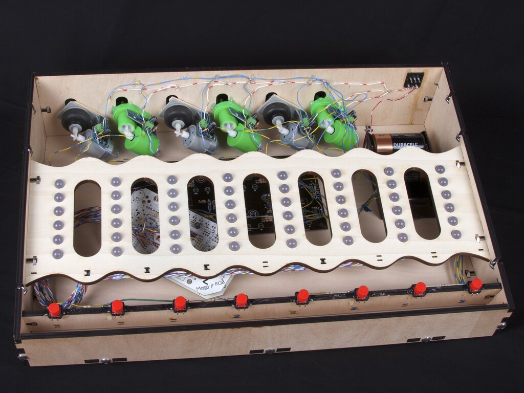
The LED grid, buttons, and pumps all mounted in the controller box. Note that we have two different styles of pump here, all of which came out of pumps with the same brand and model number on them. We’ve also added two power switches (visible on the upper right), one for the microcontroller and LEDs (3xAA, 4.5 V) and one for the pumps (2xD, 3 V).
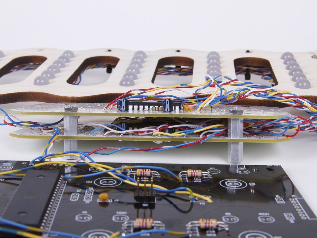
 One other detail, which we mentioned earlier, is that we need to be able to detect when the graduated cylinders tip. To do that, we use a photogate consisting of an infrared LED and an infrared-detecting phototransistor. The IR LEDs are driven by the fourth LED driver chip, and the six phototransistors are read by the AVR’s analog inputs. When the cylinder tips up, it blocks the beam, and so we can detect it.
In the photo above, you can see the wiring to the infrared components, held in place by the yellow cable ties.
One other detail, which we mentioned earlier, is that we need to be able to detect when the graduated cylinders tip. To do that, we use a photogate consisting of an infrared LED and an infrared-detecting phototransistor. The IR LEDs are driven by the fourth LED driver chip, and the six phototransistors are read by the AVR’s analog inputs. When the cylinder tips up, it blocks the beam, and so we can detect it.
In the photo above, you can see the wiring to the infrared components, held in place by the yellow cable ties.
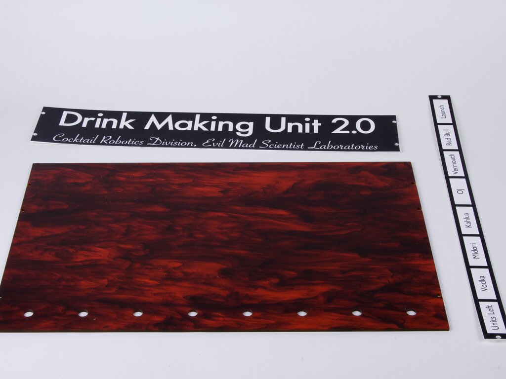
The top cover of the box is a sheet of tortoiseshell-colored acrylic, laser cut with holes for screws and buttons. We also made a nameplate and swappable labels to label different possible fluid sets.
 Add a little bit of code, and there we go.
Drink Making Unit 2.0 will be
Add a little bit of code, and there we go.
Drink Making Unit 2.0 will be You can also see a video preview of Drink Making Unit 2.0 (as a work in progress), in Make: Live, episode 5, starting at about 11:30 in.
If you can you should source pear shaped flasks, that way you’ll be able to get more of the liquid out, with much less wastage.
It’s important to not waste alcohol, after all.
Fun fact: the shishi-odoshi is sometimes affectionately known as “The Thing That Goes Doink“. :)
As each flask will be refilled many times during the event, there will be very little wasted.
Windell H. Oskay
drwho(at)evilmadscientist.com
http://www.evilmadscientist.com/
I notice you crossed out the text for your REAL controller. You know it is the cat that controls all of your decisions. At least, when the cat is interested.
That Red Bull flask is bound to exhibit some unintended drippage due to it being a carbonated liquid in a sealed flask.
But your deer chaser solution makes that pretty much irrelevant. If it goes unused for a while I suppose it may dispense unintentionally. I doubt any flask will go unused that long, being so cool and all.
Well-engineered, team. Well engineered, indeed.
-Radiodork
It wasn’t clear whether or not the carbonation would really be a problem or not. Turns out that the equilibrium pressure in the Red Bull flask was not sufficient to push the liquid up and out. If it was, we had planned to add a pressure relief "leak" to prevent slow buildup.
Windell H. Oskay
drwho(at)evilmadscientist.com
http://www.evilmadscientist.com/
Awesome bot, the wires made me think though, does anyone on the team work for Bell?
I like the way your controller looks. What are the name plates made of,
and how did you print them?
The name plates were laser engraved from two layer acrylic.
I have been looking into low-cost pumps for dispensing fertilizers in a planted aquarium. I am currently working on a peristaltic pump which should be reproducible for about $7 including motor but not the controller. A low-cost controller is the next project in the works.
I have the body on Shapeways, but haven’t opened it up for purchase because I haven’t done the testing yet. It will be open-source, so it may be useful for DMU3.
I can’t seem to post links but if you search for peristaltic and plantedtank, it’ll pop up.
Why did you make it that comlicated with pumps? It would be so much easier to mount the bottles with the ingredients on the top and just open/close the tubes to controll the flow of the fluids?
Nonetheless awsome thing.
I think that you’re referring to the use of "pinch valves" — yes, that would be another approach. Is it more or less complicated? Not really. Six motors are six motors. The main difference is whether we run wiring or tubing from the controller.
Difference 1: pinch valves are normally used with servo motors, which require slightly more care to drive than DC motors.
Difference 2: with pinch valves, all of them need to be FIRMLY CLOSED except up to one, at any given time. This means heavy power consumption in comparison to our method, which uses *no power* at idle, and runs on batteries.
Difference 3: We can’t use the cool flasks if they have to be upside down.
Windell H. Oskay
drwho(at)evilmadscientist.com
http://www.evilmadscientist.com/
So, could you give us an estimated cost for everything involved in the project? Or better yet, are you interested in selling? ;)
all bottles with rhum!!!!
The one thing that seems to be missing is a glass lab funnel.
It’s actually helpful to be able to *see* the funnel. :)
Windell H. Oskay
drwho(at)evilmadscientist.com
http://www.evilmadscientist.com/
Then you need a stainless steel funnel!
Fantastic ‘bot but the plastic funnel just doesn’t match the apparent quality of the rest.
I was too far away to attend barbot 2011, so anxiously await a video of your DMU 2.0
in action, preferably with the non-fuzzy controller. Do you add Red Bull to make Red Russians?
I’ve just spotted the Octolively PCB used as the ‘164P breakout board for this project!
I picked up some empty Arduino PCBs for nearly nothing on e-bay that I minimally populate as needed to make ATmega breakout boards, but here you have managed to re-purpose something like 2 Meggy’s, and Octolively and six Eggbot etcher boards! Great piece of self-hacking!
Oh, and the DMU is great too!
Oh yes, this was a *great* recycling project– thanks for noticing! Sometimes the best board to build is none at all. :)
Windell H. Oskay
drwho(at)evilmadscientist.com
http://www.evilmadscientist.com/