


Ryan writes in,
| “I have a question about moving a project off a bread board and onto a project or perf board. Basically what is the best way to do without a lot of rework? This will be my first time doing this and I was just wondering if there were any best practices so that the final product looks clean and organized and I don’t have mountains of solder on the back side.” |
And it’s a good question.
It turns out that we don’t actually use solderless breadboards all that often– most of our physical prototyping is soldered directly on perfboards, like so:
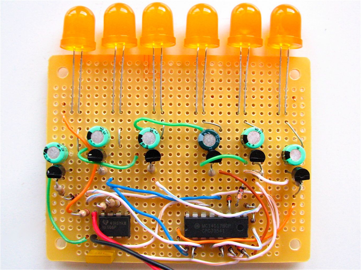
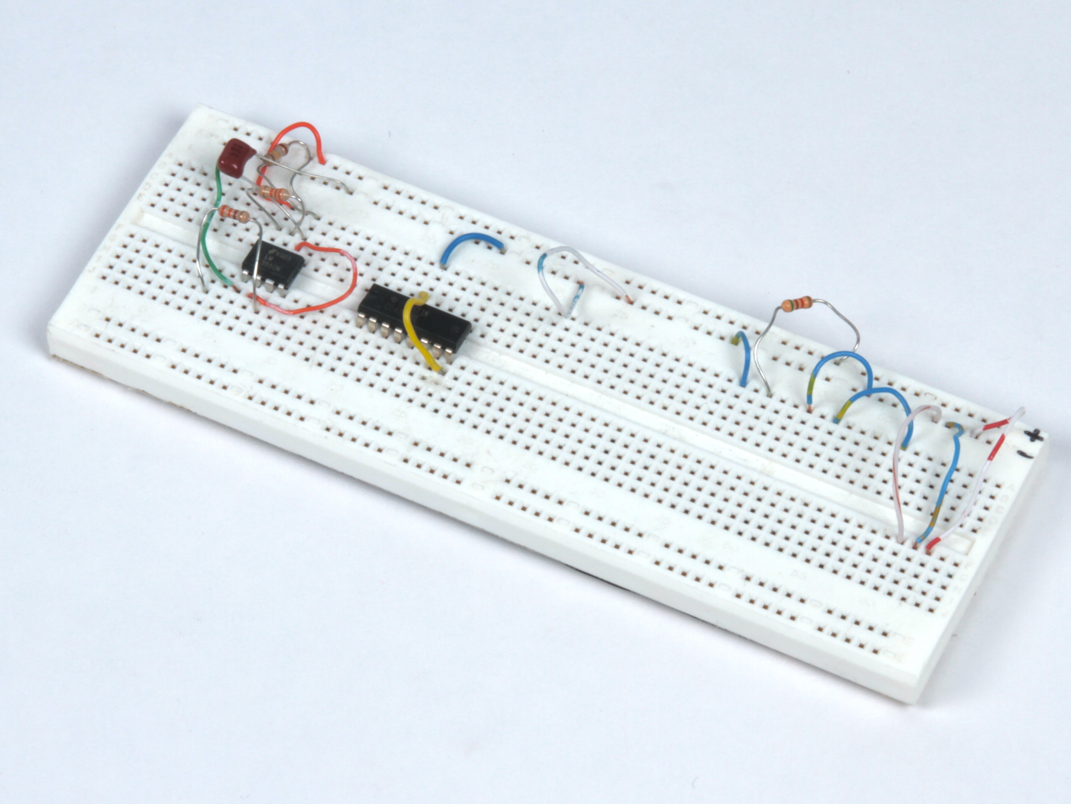
However, that’s an acquired skill, and there is indeed a bit of a leap from breadboard…
… to protoboard:
Now, it turns out that there’s actually a neat and happy medium from (of all places) Radio Shack: A protoboard shaped and wired up like a breadboard.
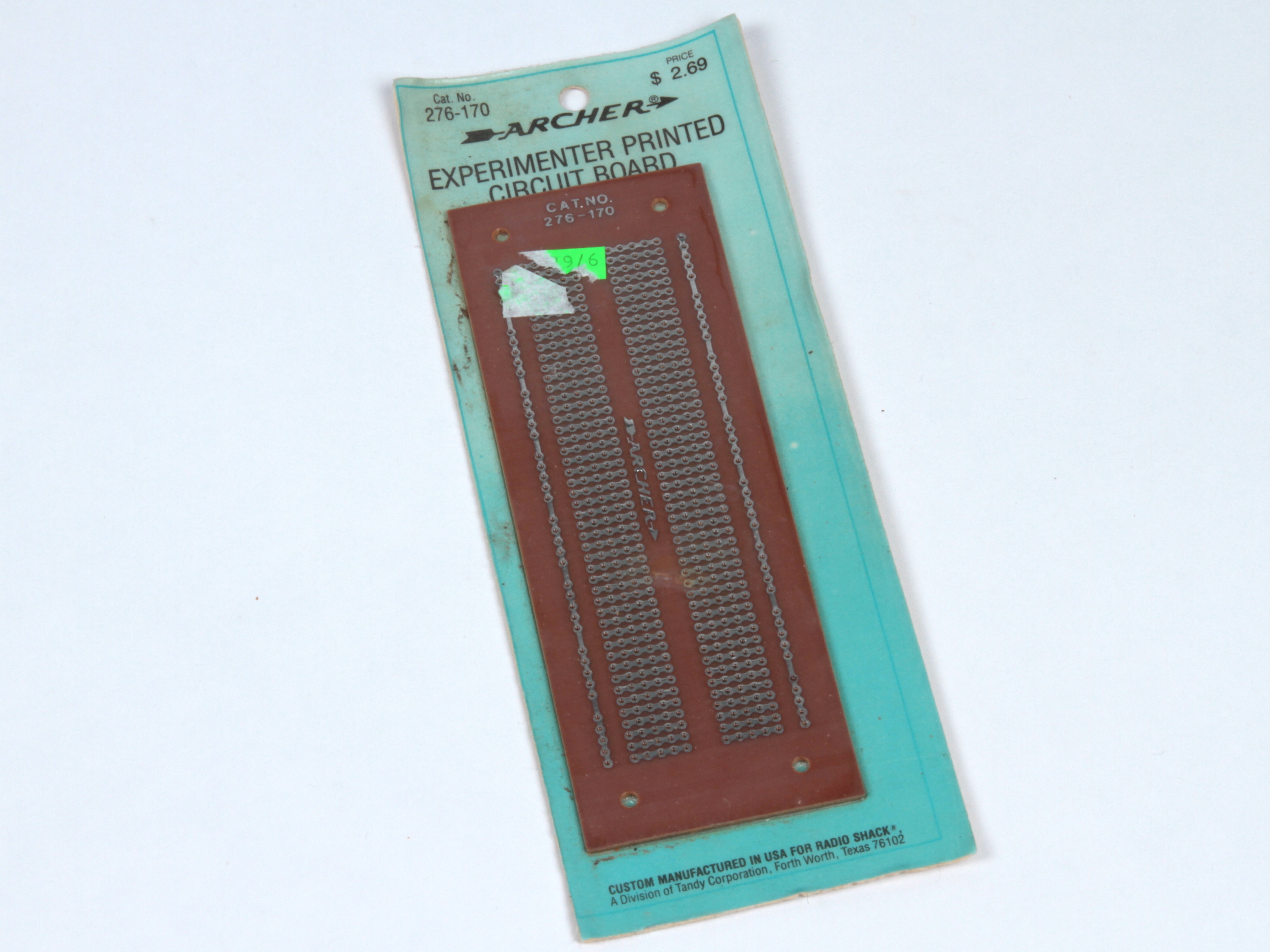
Ours is in older packaging, but catalog number 276-170 is still around, still cheap, and as they say, “available at most stores.”
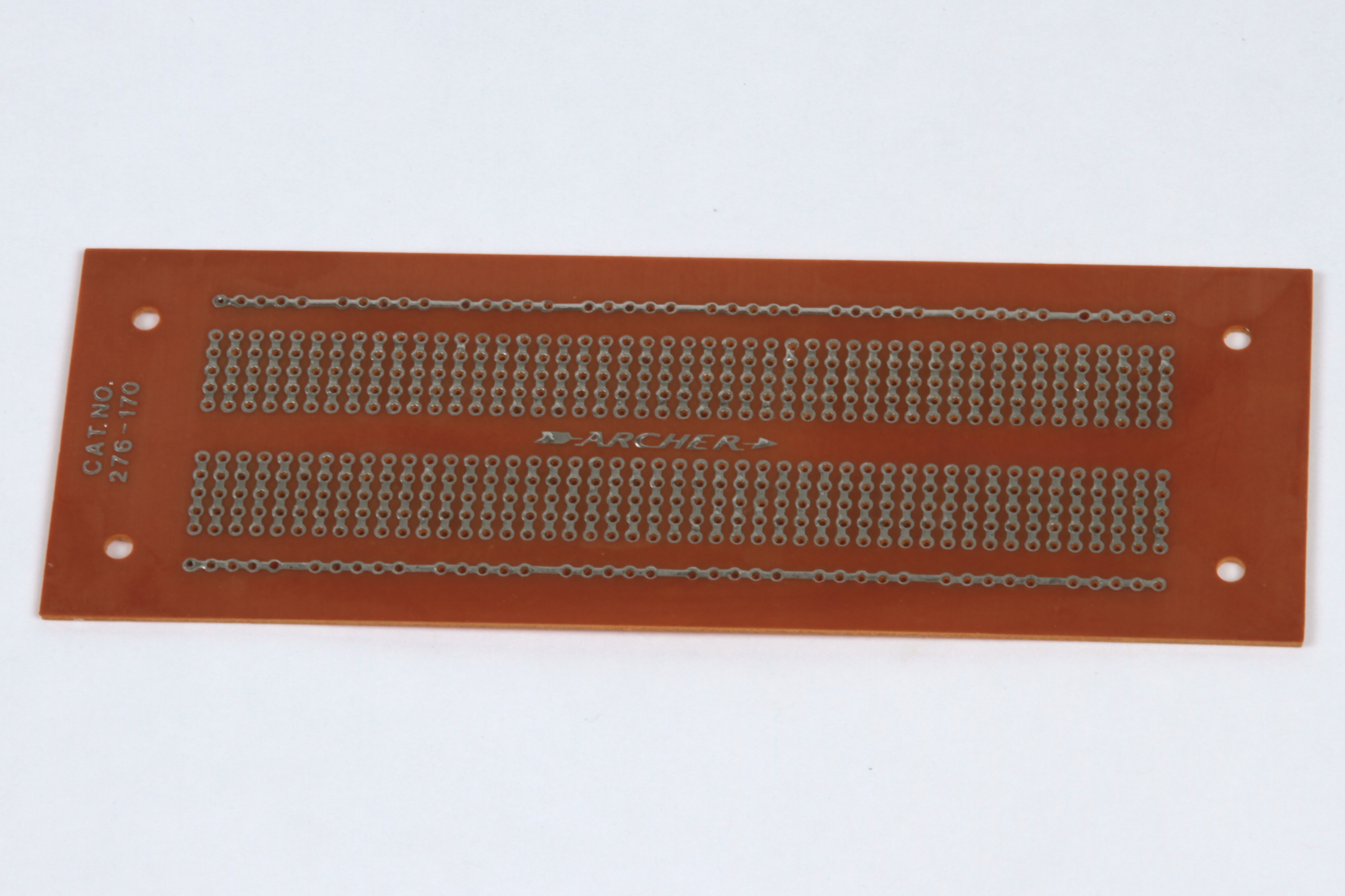
The bottom side of the board has the same wiring as a typical solderless breadboard, albeit with only one stripe down each side.
This layout means that you can usually duplicate your breadboard circuit exactly, soldering as you go, to make a permanent copy of your breadboarded one.
Doing so, you also get familiar with the process of soldering parts together on the protoboard– a useful skill, especially if you ever need to build something that doesn’t fit on a breadboard so easily.
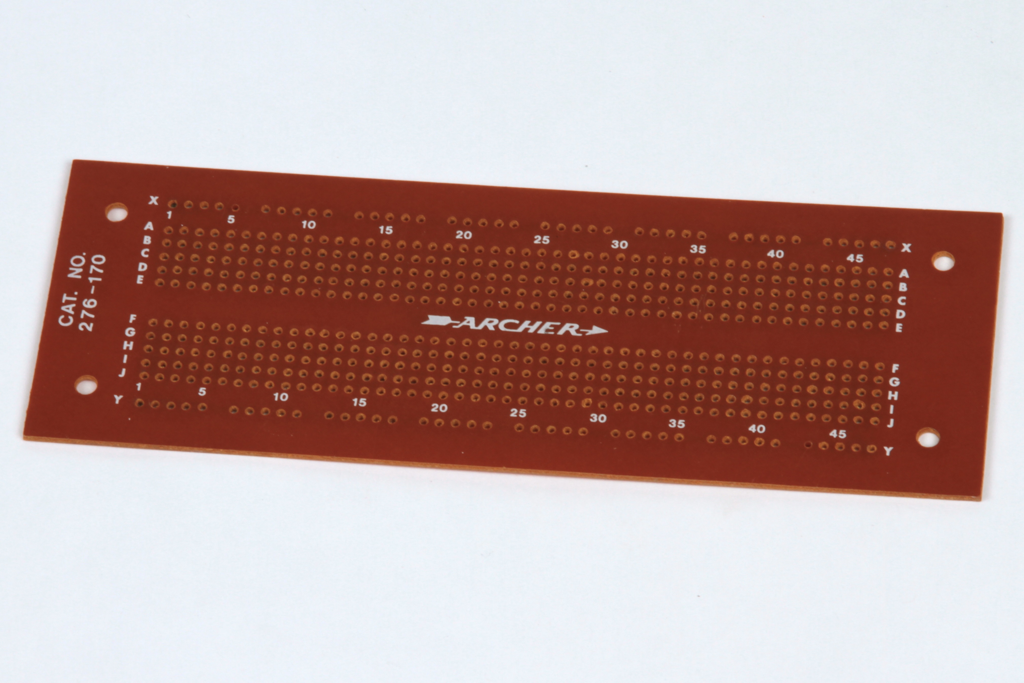
Here’s the top side of that board, which might look more familiar to breadboard fans.
Love that vintage Archer branding, which was lost somewhere along the way.
Not seen that breadboard layout protoboard before- neat.
I’m part way through my first attempt to go from breadboard to stripboard, which was made much easier by TinyCAD and VeeCAD. Didn’t take too long to come up with the following…
http://jtlog.wordpress.com/2010/02/21/my-second-currentcost-development-board-circuit/
Would have been even quicker if I’d read the instructions first and used the libraries provided with VeeCAD, which included the 555 timer I was adding by hand! Doh!
my problem was how to documentate the circuit on the breadboard. I found fritzing (http://www.fritzing.org) which does very well… (should work for protoboard as well ;-) )
I haven’t been able to find anything published about how to solder on a perfboard. Do you know of anything?
Try this:
http://itp.nyu.edu/physcomp/Tutorials/SolderingAPerfBoard
When you say “soldered directly on perfboards”, you mean the kind with copper rings around each hole, not no copper at all, right?
My comment has more to do with how you breadboard than transferring it to the proto board. If you look at the layout of a BLANK breadboard, you see that the sets of holes all go in one direction (except the rails.) Call that vertical. If you lay out your wires so they all go in the other direction, horizontal, except when you have to jump the gap between the two sides, your finished project looks much neater. To go from one side to another, lay a wire to a blank set, then connect that blank set to its opposite, and finally another wire to the destination. Wires then do not cross each other, and troubleshooting also becomes much easier. Troubleshooting on a soldered protoboard can be a royal pain, so anything that makes it easier is by definition good. Just my two cents…
This is a nice breadboard style protoboard as well, including 3 power rails on either side:
http://www.busboard.us/bps-br1.htm
I buy them locally, but you can also get them from Mouser.
Cheers,
ao. [ http://www.technoetc.net/blog ]
I’ve been thinking about building prototypes on breadboards too. I find that after I spend the time building a project on the breadboard, I don’t want to take it apart to reassemble it on a perfboard. I end up wishing that I had just taken the extra time to solder it in the first place.
When I go from breadboard to protoboard I draw out where the components will go to get an idea of spacing. Then start by soldering on a socket for the IC and go from it’s #1 pin out to the components until I dead end (using those other components’ leads as traces to connect them) and work my way around to the last pin. Hook all the grounds together and put on any off board components I might need. It is a little bit more work but I’m a huge fan of breadboarding and playing with a circuit before I make it permanent. I used to go directly to protoboard but ended up with a lot of headaches and scrapped circuit boards so I learned to breadboard and have never looked back.
There’s also this, the best of both worlds: http://www.dipmicro.com/store/MQB-2
The protoboard fits over the breadboard, with traces to match the breadboard connections. Insert component leads through the protoboard into the breadboard. When it’s working, solder the components on the top side of the protoboard and remove the breadboard. Whalla!
You should also consider this: either you spend time troubleshooting a perfboard circuit, or you spend that time designing a proper PCB with tools that do a number of "troubleshooting" checks for you (e.g. the DRC check in EagleCAD). I find designing a proper PCB is much more fun than troubleshooting some crappy wiring error on a piece of perfboard spaghetti.
Once I started designing my own proper PCB’s I have had a 99% works-first-time rate, and haven’t looked back since, not even for one-offs.
That’s fine, with a few caveats. Creating a custom PCB for a project small enough to fit on a breadboard is usually at least 20-50 X more time consuming and at least 20-50 X more expensive. (Figure at least two days for your board to arrive and at least $50.)
In my experience, it’s usually not worth the time or expense for a one off circuit small enough to fit on a breadboard.
Windell H. Oskay
drwho(at)evilmadscientist.com
http://www.evilmadscientist.com/
If a person is cooking their own PCBs at home (using any number of the home-etching and drilling methods linked to from your blogs and other places on the EMSL website), the argument about $50 boards and waiting two days or longer are somewhat moot points, no?
Not trying to be argumentative, but for a single-sided protoboard, there are much cheaper ways to put one together than farming it out to a prototype company, if one has the time and tools to do so.
Absolutely correct; if you make the boards yourself, then it’s only 2-5X the price and 2-5X the amount of time. :D
If the project is simple enough that you could wire it up by hand in 1 hour (as most things on a breadboard are), it’s still very likely to take at least an hour to lay out and route and DRC and export, and at least an hour to expose, etch, clean, and drill. Usually longer in my experience. I have laid out and hand etched circuits for one-offs, but it’s generally been for a circuit that wouldn’t work on protoboard. You certainly *can* do it, but I can’t say that I’d recommend it.
Windell H. Oskay
drwho(at)evilmadscientist.com
http://www.evilmadscientist.com/