


Last year David Friedman published on his blog Ironic Sans an interesting design concept for something that he called The Bulbdial Clock.
That’s like a sundial, but with better resolution– not just an hour hand, but a minute and second hand as well, each given as a shadow from moving artificial light sources (bulbs).
We’ve recently put together a working bulbdial clock, with an implementation somewhat different from that of the original concept.
Rather than using three physically moving light sources at different heights, we use three rings of LEDs at different heights. Within each ring, we only turn on one LED at a time, so that we only have a single effective light source– it can light up at different places from within the ring. The three rings are located above one another so that they each project light onto the rod in the middle, making shadows of different lengths.
Additionally, for fun and clarity, we used red, green, and blue LEDs for the three rings, making each shadow hand of the clock a different color. Each ring has 12 LEDs, and the 36 LEDs are efficiently multiplexed by an AVR microcontroller that also handles the timekeeping part of the project.
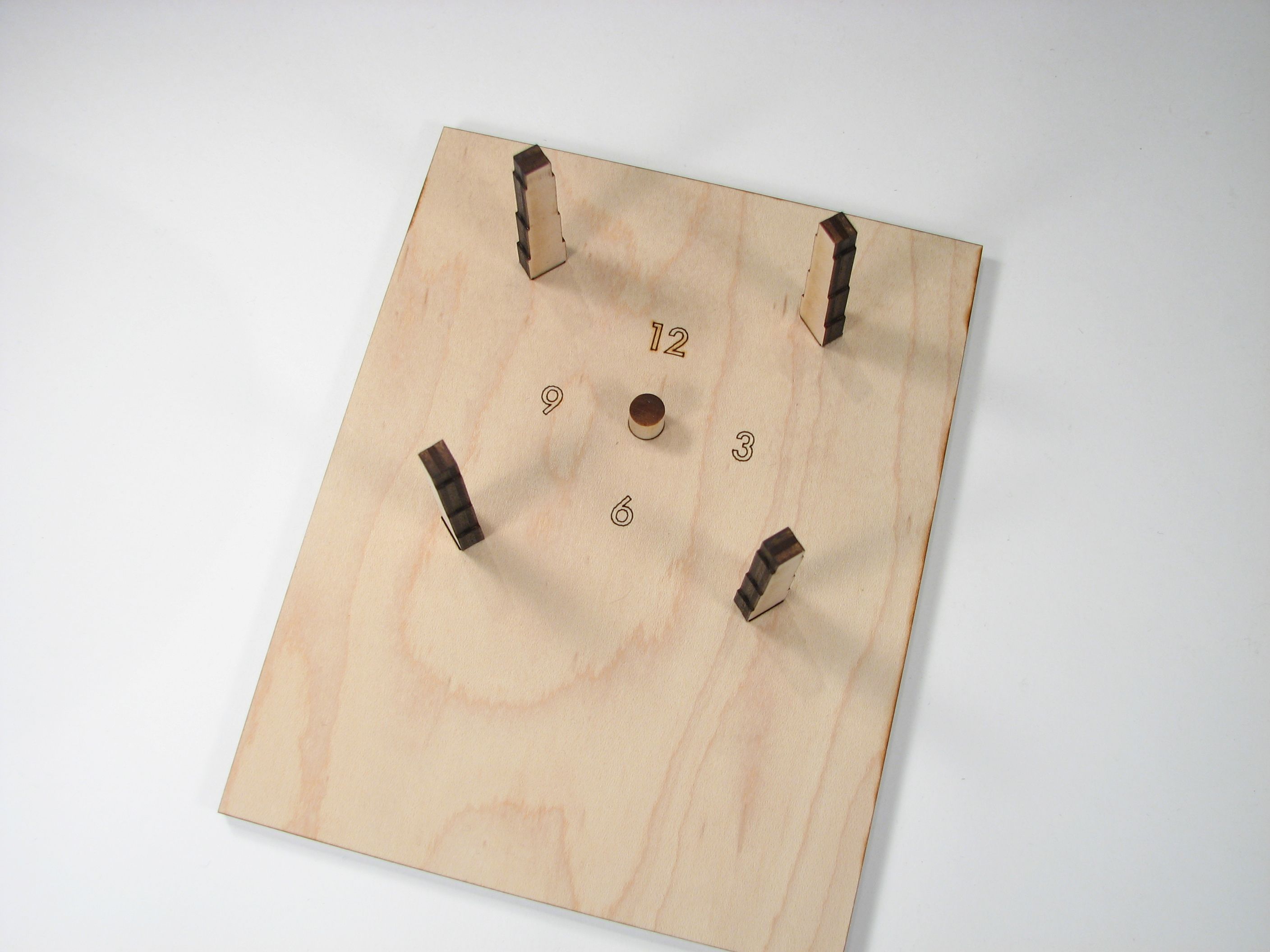
This clock is mostly built out of laser-cut plywood.
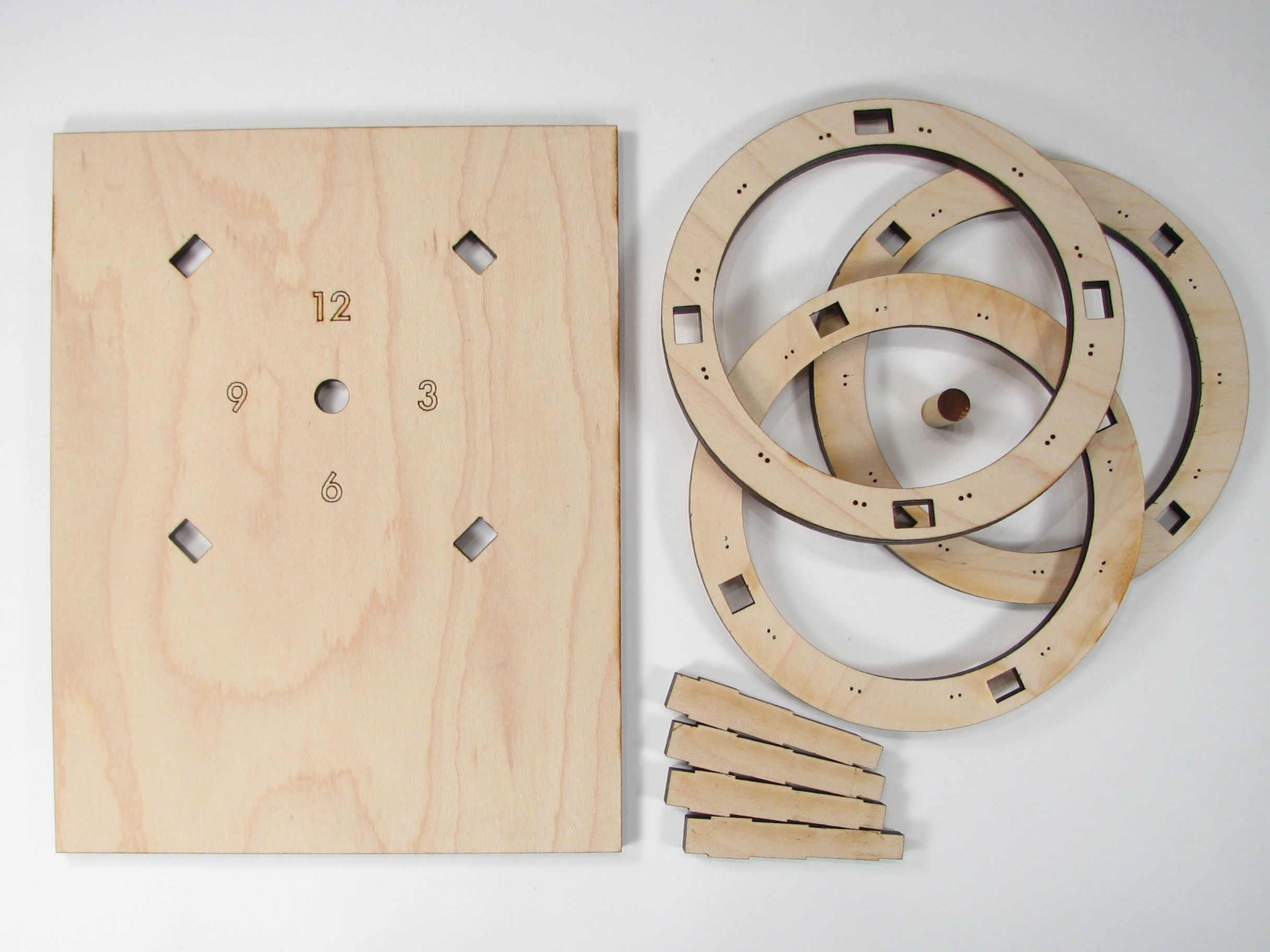
This is 1/4″ (6 mm) plywood, which holds remarkable precision with the laser cutter. There are three rings, shaped spacers that keep the rings above the base with the clock face, and a hardwood dowel rod.
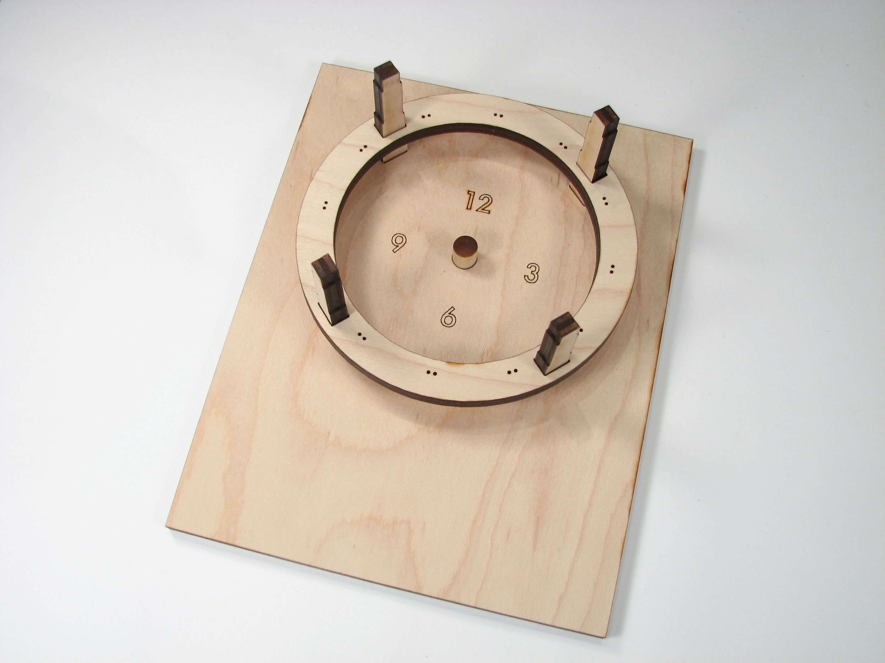
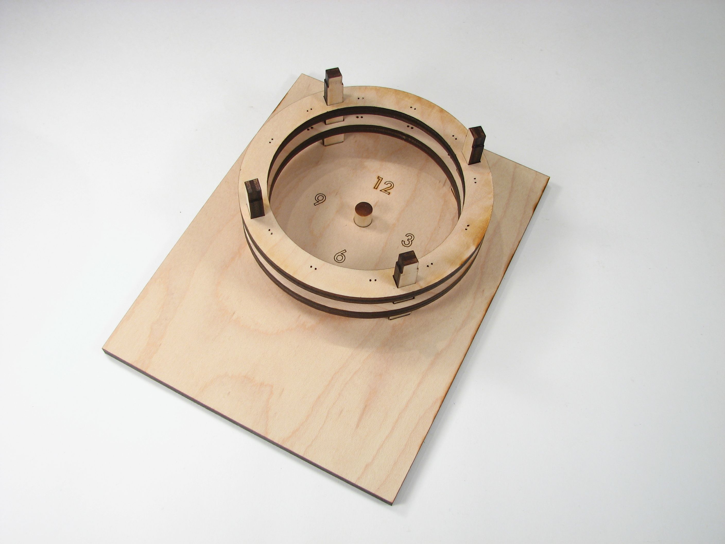
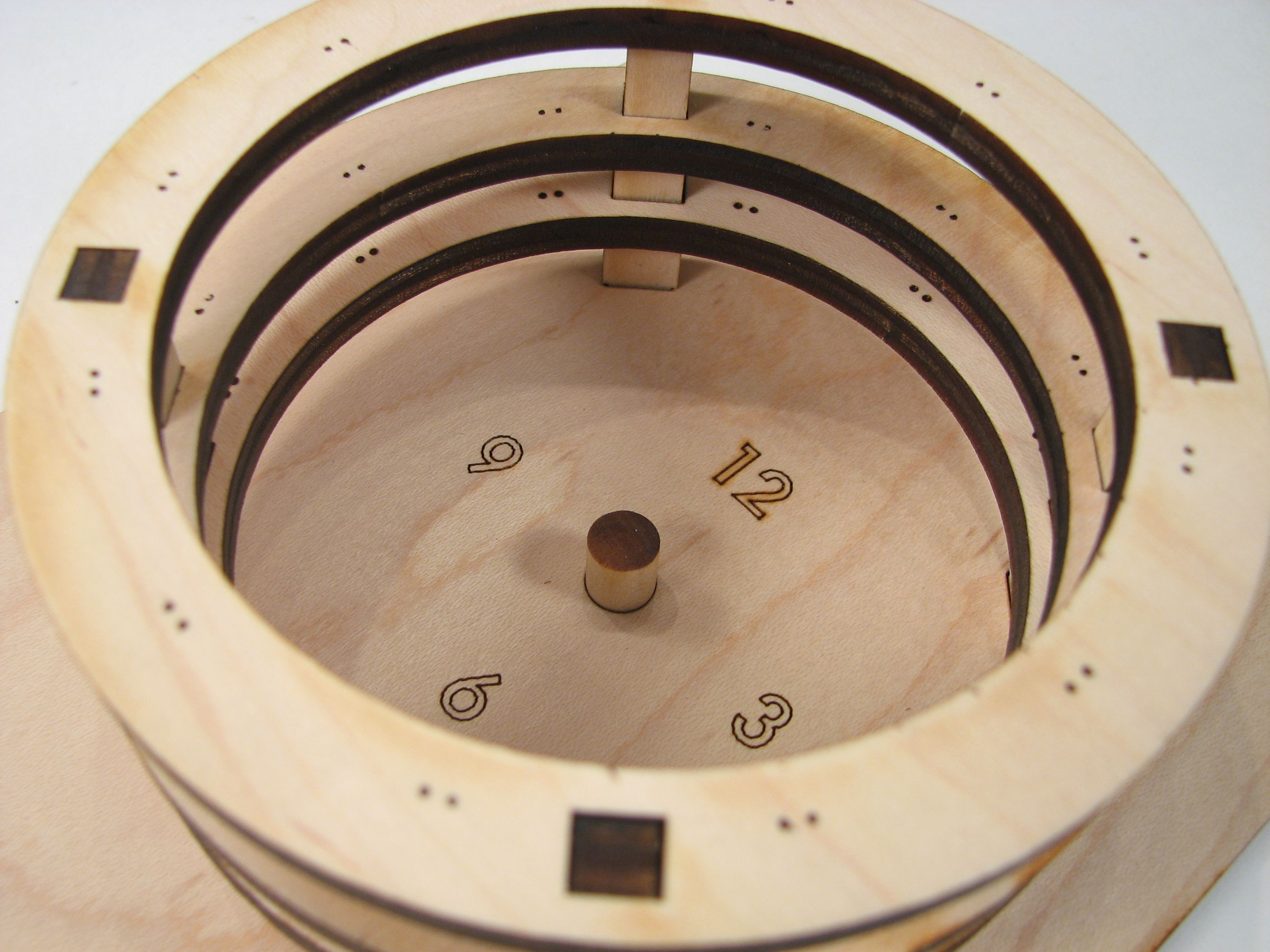
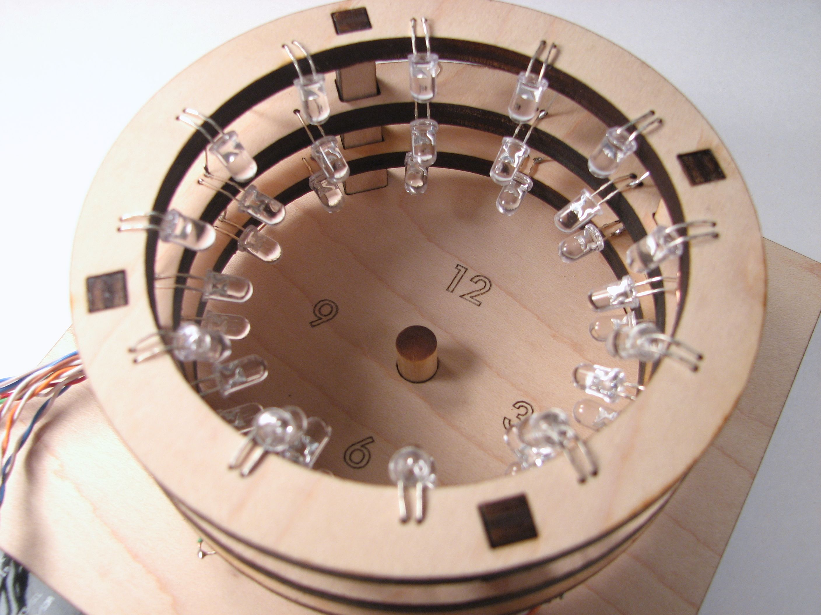
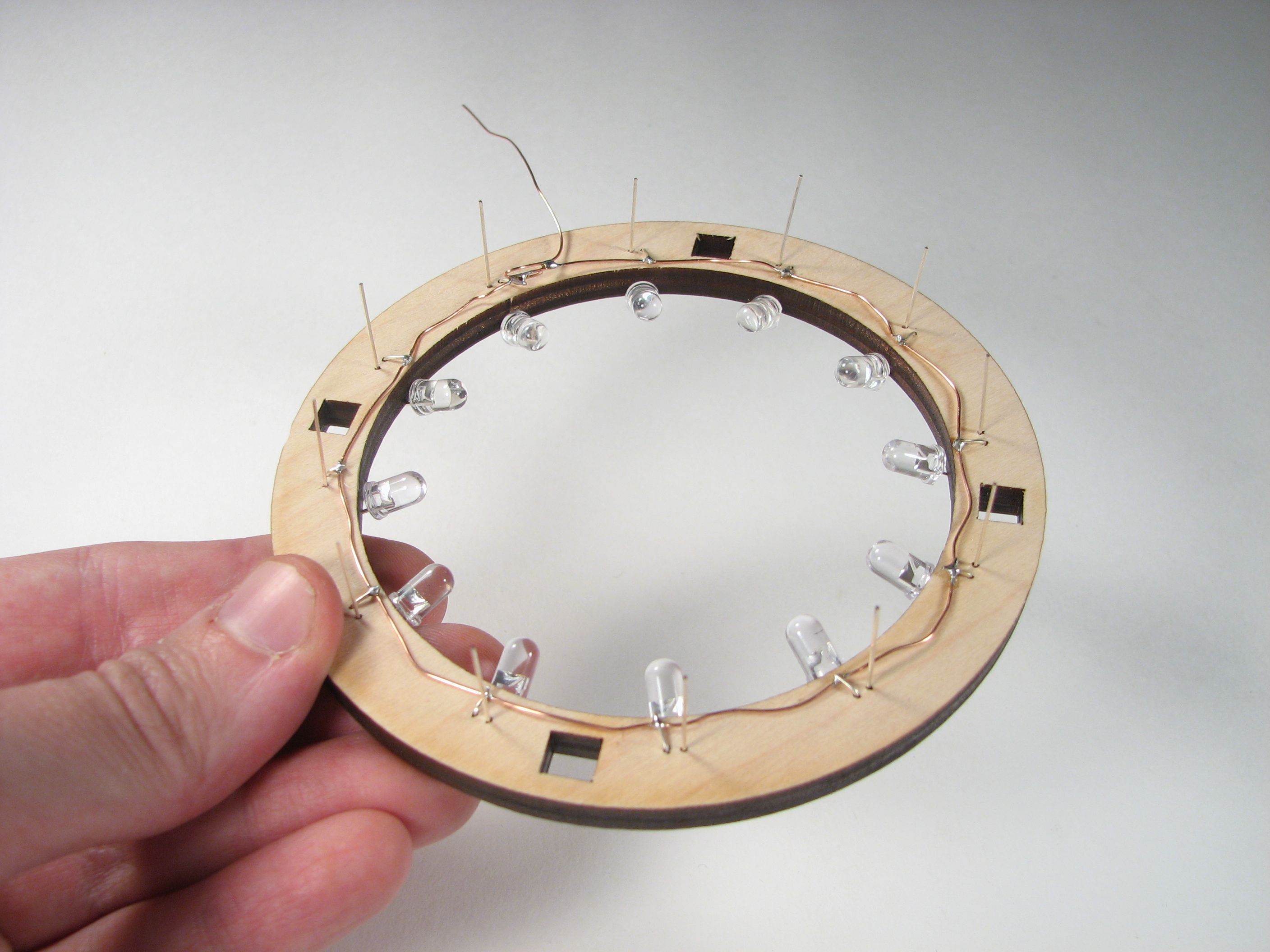
It’s really quite a three-dimensional project! The rings each have pairs of small holes in them to mount the LEDs in place.
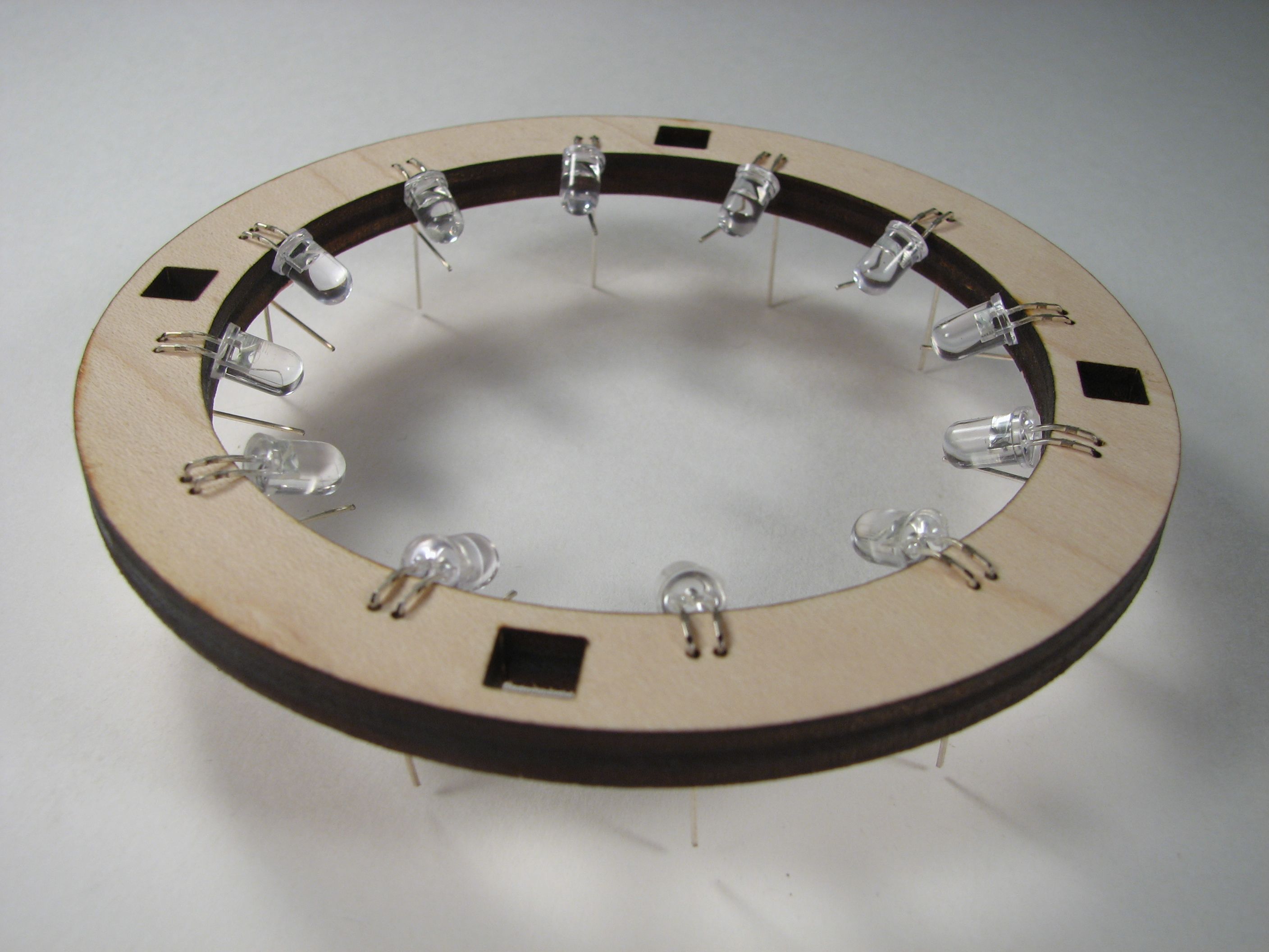
Each of the rings gets stuffed with 12 LEDs, with the correct orientation and spacing– long enough leads– that they can point towards the rod (and make good shadows) once they are in place.
Since each LED is only supposed to be on one at a time, we can drive the whole array pretty easily, and directly from the microcontroller, Here we are turning this array of LEDs into a single common-anode unit, by hooking all of the LED anodes together. Likewise, after we stack these, we connect the cathodes — vertically for the three rings– and hook those up to the microcontroller as well. For three rings (colors) and 12 cathodes, that means that we need 15 pins to control the array.
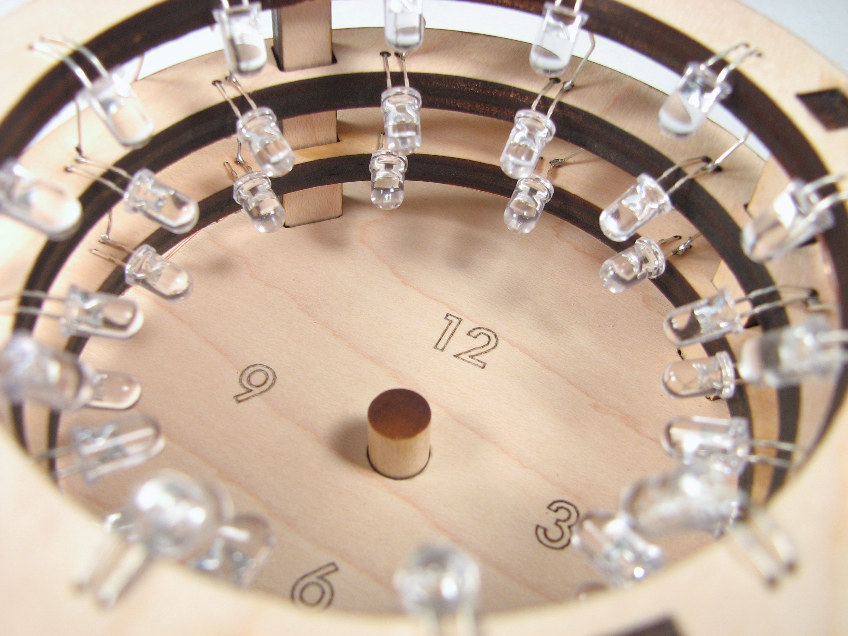
And the stack up is complete.
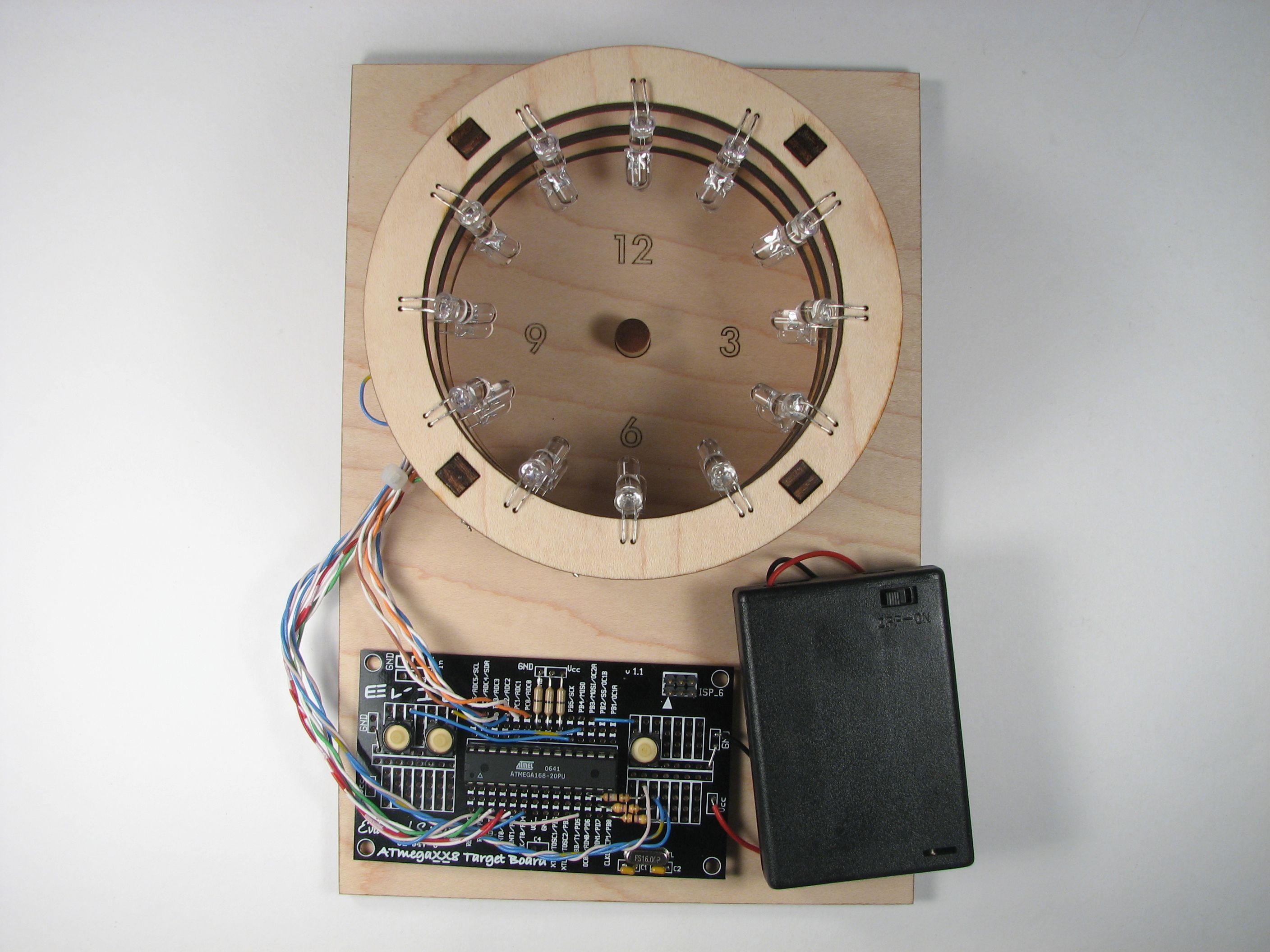
The next step is to add the control electronics. I used one of our business card boards, an ATmega168 microcontroller (programmed through a USBtinyISP), along with a 16 MHz crystal oscillator, a 3xAA battery box with switch and three tactile button switches. Not to mention a snarl of wire. There are also three resistors, two 50-ohm and one 100-ohm, which are used when driving a red LED, or blue or green, respectively. Because only one LED is on at a time, we only need one resistor for each color.
Of the three buttons, two are used for setting the time– one is fast advance, one is slow advance. The other button turns on or off the LED, but does not turn off the microcontroller. When the LED is on, the circuit uses about 26 mA of current. When the LED is off– just timekeeping, not displaying — it uses about 11 mA. These could both be reduced by using larger resistors and reducing the speed of the microcontroller.
(Aside: These parts were chosen principally for being the ones lying around. However, they’re mostly the right kinds of thing. The microcontroller is about the right size for the number of pins that are needed for this project, but we probably could have gone with one that had less memory– the control program is pretty small. A quartz crystal oscillator is nice because it’s *a clock* and shouldn’t lose much time. But 16 MHz is much faster than is needed, and the power consumption of microcontrollers depends on clock speed, so I’d pick (maybe) a 1 MHz crystal next time. The battery box is actually just right– 4.5 V provides comfortable headroom for driving blue and green LEDs, but not too much, and AA cells give sufficient capacity to make a non-annoying battery powered device, once we tweak that power consumption a bit more.)
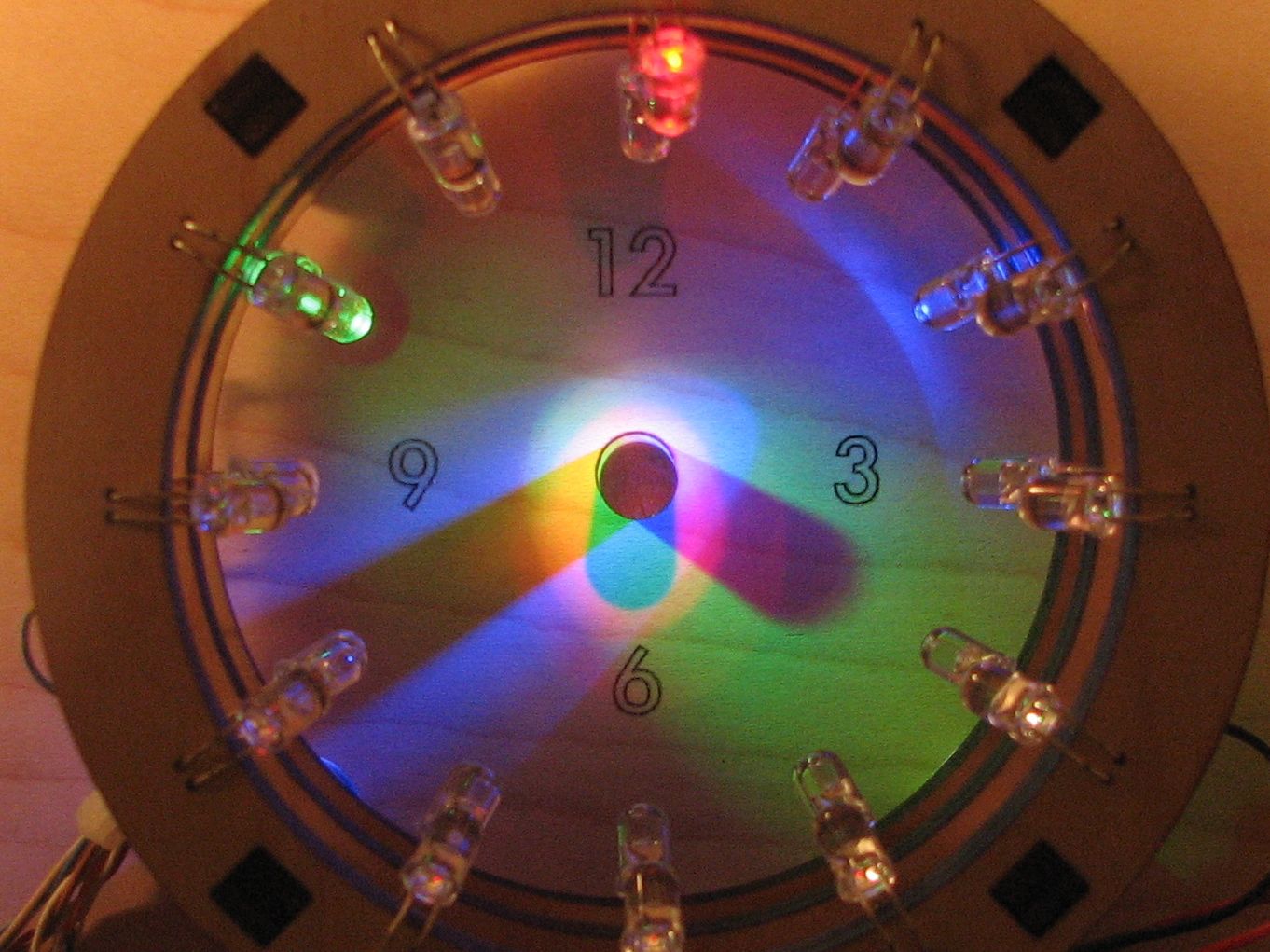
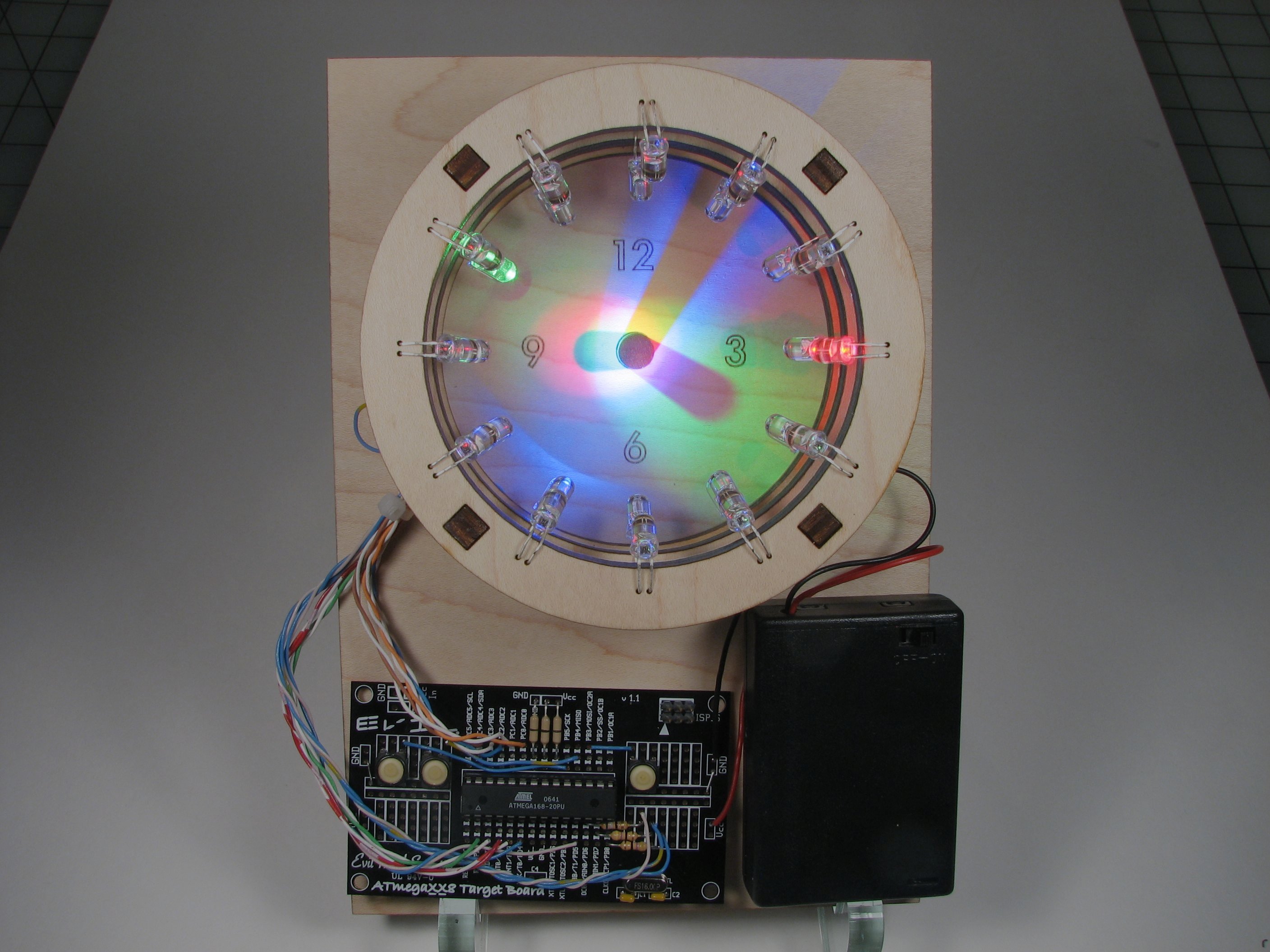
As we have noted, it’s pretty tricky to get good photos of LEDs, but you can kind of get the idea here– just imagine that the colors are bright and vibrant.
In this photo the time is about 6:20:40. (Like many clocks, it’s hard to read with high precision. Even so, the seconds help to create the sense that something is happening.) The short hand, the hour hand, is created by the shadow of the red LED, and points to 6, indicating 6 o’clock. The medium hand, the minutes hand, is created by the shadow of the green LED, and points to 4, indicating 20 minutes past the hour. The seconds hand, the longest one, is created by the shadow of the blue LED, and indicates about 40 seconds past the minute.
What’s *really* neat about this is how the colors interplay. Where all of the LEDs hit, a white color (additive RGB) is produced. Then, as you subtract one of those three colors– as in the shadow of a single LED, the results are subtractive colors, and the hands on our clock face are in the colors cyan, magenta, and yellow. It’s just magical.
So that’s our new bulbdial clock; you can see additional a few photos in our flickr photo set here.
One more thing: We are thinking about making a kit version of this project (under license from David Friedman)– and we’d really like to have your feedback before we go further. There are a few obvious things that we’ll take care of– like a circuit board with dedicated (and labeled) buttons, a lower-frequency crystal oscillator to reduce power consumption, and holes to hang it on the wall. But we’d like to hear your other suggestions as well. :)
Update (December 2009):
We’ve listened pretty extensively to all of the feedback here (Thanks!) and reworked the project from the ground up. Amongst other changes, the new version has a plug-in power supply and classy outer case. We have just released the kit version, and you can read more about it here.
How close are you guys coming to actually making a kit for this? I’m just curious because I’m so anxious. 2 weeks? 2 months?
That’s so cool,I want to have one
You might consider playing with the shape of the gnomon (center post) to make the shadow shapes a bit less "baseball-bat"-y.
whoaw, this is one of the coolest things i’ve ever seen…
need this kit, i’ll buy it immediately :)
soo pleeeease publish this kit
Please do go ahead with the kit, and make it available for Indian customers, I’ll be the first to purchase it…. Awesome idea man!!
I want one! I will commit to the Kit!
Jules
How about going the whole hog and dimming the LEDs so that it cant be read in the dark
How about going the whole hog and dimming the LEDs so tat it cant be read in the dark. Id still have one
I think most (if not all) of the AVR xx4’s have a secondary clock input for a standard 32 khz clock crystal to keep time without worry (my 164 does, at least). The one they’ve used in the Arduino Mega does too, and that thing is just bristling with IO pins (though they seem to have left the clock pins unconnected). :(
—
I think I am, therefore I am… I think
It looks gorgeous!
And with exposed electronics it looks geeky. :)
If you hide all the electronics and diodes, it’ll look cheap-chineese :(
Kit is most wellcome.
A sundial that doesn’t use sunlight!
Now make it run on an endangered plant species!
Sorry, I couldn’t resist. :-)
It’s an awesome project.
That’s the coolest thing ever! I would totally make one if there was a kit available! :)
Make it into a kit!!!!!!!!!!!!!!!!!!!!!!!!!!!!!!!!!!!!!!!!!!!!!!!!!!!!!!!!!!!!!!!! I’ll buy 2!!!!!!!!!!!!!!!!!!!!!!!!!!!!!!!!!!!!!!!!!!!!!!!!!!!!!!!!!!!!!!!!!!!!!!!!!!
Please create the kit. I absolutely would buy one.
I would SO buy this kit. Probably 2 – wait – 3, I have loads of geeky friends.
i really like it. A great use of the high brightness and low cost leds we have available these days. I’d happily buy a kit when its available..
Ben
I want one! Make a kit available and I’ll buy one.
http://www.lotusinvention.cn/ART/arm/RotatingColorWheel.htm
Making the electronic part is EASY. Thats not hard at all. basic knowledge of the atmega (using a timer) and multiplexing should do. However, I have NO way of making such a nice wooden structure. Lucky you have a laser cutter -_-
If you could post some solidwork files/any type you use on how you made the wooden "components" and I would be your best friend. I REALLY want to build this.
Personally though, I would have it fade from one led to another…. that way the shadow is moving slowly :P
I’d by a kit, or just the electronic parts as a kit.
Clock Accuracy:
To increase clock accuracy you could use a the 60Hz from the power company as a time base. Use a 110 to 9V AC power blob, and pick off the 60Hz before rectifying, filtering, and regulating the DC to operate the clock. The power company goes to great lengths to ensure that over time their 60Hz signal is very accurate. A 9V button battery could provide the backup power to keep the voltage regulator from dropping to zero. You can buy Extremely accurate crystals too, but even these will drift if the temperature changes.
No-ish…. actually a 32.168Hz is PERFECT for accuracy since clock cycles on IC’s would work with the 2-bit integers.
I think you mean 32,768, (not 32,168) and even these crystals will lose up to 4 seconds per day.
The Power company accuracy is much better than that. They usually are accurate to about 1 or 2 seconds per year. (Provided the power doesn’t go out), and with a 9V battery backup even that issue is handled.
Simpler Construction.
If you use a piece of 4 inch pvc pipe you don’t need to cut out 3 rings. Just mark an drill the holes at the proper angles (30 degrees for hours), (6 degrees for minutes and seconds), if you add additional LED’s as suggested above. I am thinking of building one using this idea. Laser cutting is not as easy as cutting a piece of pipe.
I have an Idea that would make the clock hand resolution better and simplify the wiring as well. If you had only two rows (rings) of LED’s one row has 12 LED’s for hours , and one row has 60 LED’s for minutes and seconds. For the 60 LED row, each of these 60 LED’s is a bi-color led. Using charlieplexing you can drive all 132 LED’s independently with only 12 microprocessor pins. Since charlieplexed LED’s are always wired in pairs of inverted polarity the 60 LED’s that make up the Minute and Second hands would be automatically wired back to back (the standard configuration for a bi-color LED. With this configuration you still get Hours, Minutes and Seconds. The Minute and Second hands would be of the same length (post shadow height) but would be of different colors, so it would be easy to tell them apart!
So what’s the scoop on this? Have you come up with a kit yet? Would be interested in a kit or at least instructions on how to build it.
Great project! I’m always looking for unique projects to build.
does anyone know if there is a kit for this??
There is not yet; there will be soon.
—
Windell H. Oskay
drwho(at)evilmadscientist.com
http://www.evilmadscientist.com/
My electronics skills are quite rusty, but I’d love to be build this clock for my gf for Christmas. Could you provide more detailed instructions on stuff like the LED programming programs and all that? Or do we have to wait for the kit? Thanks.
We’re in the process of redesigning this, and we’ll release the design for hardcore DIY when we release the kit.
—
Windell H. Oskay
drwho(at)evilmadscientist.com
http://www.evilmadscientist.com/
Is there a projected date for the completion of the kit?
It would be great to have the kit in time for Christmas…
Think of each of the 36 leds as a cell in a spreadsheet of 3 cols (A-hours, B-minutes, C-seconds) and 12 rows (1-12). 3 cols + 12 rows = 15 ‘wires’. To select any cell requires two inputs, a col and a row. Always select 3 cells. Some examples:
12:00:00 – A1, B1, C1
03:15:00 – A4, B4, C1
06:30:45 – A7, B7, C10
09:41:32 – Cannot do exactly, because minutes and seconds must be multiples of 5. It would take 60 leds to cure this. I assume this time would round down to 09:40:30 – A10, B9, C7
A followup on the spreadsheet comment. If you look at the picture above with the hand holding one of the wooden rings, you can see the copper wire connecting all 12 LED’s on the ring. Let’s connect this copper wire to pin A; the other rings will similarly connect to pins B and C respectively. The second lead from each LED on a ring can be connected vertically to the other two corresponding LED’s when the rings are stacked, and connected to the microcontroller. Now we have 3 vertical LED’s connected to pin 1, and 3 vertical LED’s connected to pin 2, etc., thru pin 12. We thus have our 15 wires. (Note these ‘pins’ are not literally pins of the microcontroller). Since the article says the whole array can be driven directly by the microcontroller, perhaps ‘persistance of vision’ is used in the code as follows:
loop
switch all 15 pins open # all LED’s go out
switch pin A closed # enable only the ‘hour’ ring
switch one pin closed from 1-12, depending on the hour
delay # one A ring LED is ON
switch all 15 pins open # all LED’s go out
switch pin B closed # enable only the ‘minute’ ring
switch one pin closed from 1-12, depending on the minute
delay # one B ring LED is ON
switch all 15 pins open # all LED’s go out
switch only C closed # enable only the ‘seconds’ ring
switch one pin closed from 1-12, depending on the second
delay # one C ring LED is ON
end loop
Although only one LED on each ring is pulsing ON and OFF, and only one of the 36 LED’s is ON at any given time, persistance of vision will allow three LED’s to appear statically ON if the loop is repeated quickly enough.
For the kit version, are you planning to run this clock with an ATmega168/328 with the Arduino bootloader? I know that you will have to change the settings for the slower clockrate, but that’s easily done by editing a line inside the boards.txt file. I don’t know about others, but it would definately be easier for me to hack if it had the Arduino bootloader loaded onto it. Really cool project BTW.
Yes, the kit version has a ‘168 with the Arduino bootloader.
—
Windell H. Oskay
drwho(at)evilmadscientist.com
http://www.evilmadscientist.com/
Nice. I’ll have to get me one of these.
Thanks.
it’s just… this thing is beautiful but… of Radio Shack’s contributions to society (pushy cell phone clerks, questionable brand-everything, etc..) i think their black plastic project enclosure is truly a curse on all of Earth.
But what a beautiful and clever project!!!