


With all the cool things that you can do with LEDs today, there is still one thing that’s lacking: simplicity. If you want to run a bunch of LEDs at a time, you usually end up spending a fair bit of time worrying about series and parallel combinations, matching brightness, and picking load resistors. Or, if you’re a beginner, maybe you only get one third of the way through the previous sentence– wondering if you’re already in over your head.
Suppose that you want to make a big LED display for your window or wall: maybe it’s your logo, a symbol, your favorite 8-bit character, or maybe even a sign that spells out words like “OPEN” or “ON AIR.” How do you go about it? The usual DIY solution involves drilling holes in a panel to fit your LEDs, then spending a heck of a lot of time wiring everything up– ending up with one resistor per LED (and a three-dimensional mess if you happen to look at the back side of the panel). And, if you do everything in the most obvious ways, it can even end up consuming a surprising amount of power.
While I have certainly spent my share of time constructing things with the aforementioned technique, at some point it becomes clear that there has to be a better way. In this day and age, shouldn’t LEDs be about as difficult to play with as, say, a Lite Bright? Today we are releasing a new open-source hardware and software design that takes some of the sting, complexity, and mess out of playing with LEDs. It’s a versatile and powerful light-emitting pegboard that lets you efficiently drive hundreds of LEDs in whatever configuration you like, without so much as calculating a single load resistor.

So how does it work?
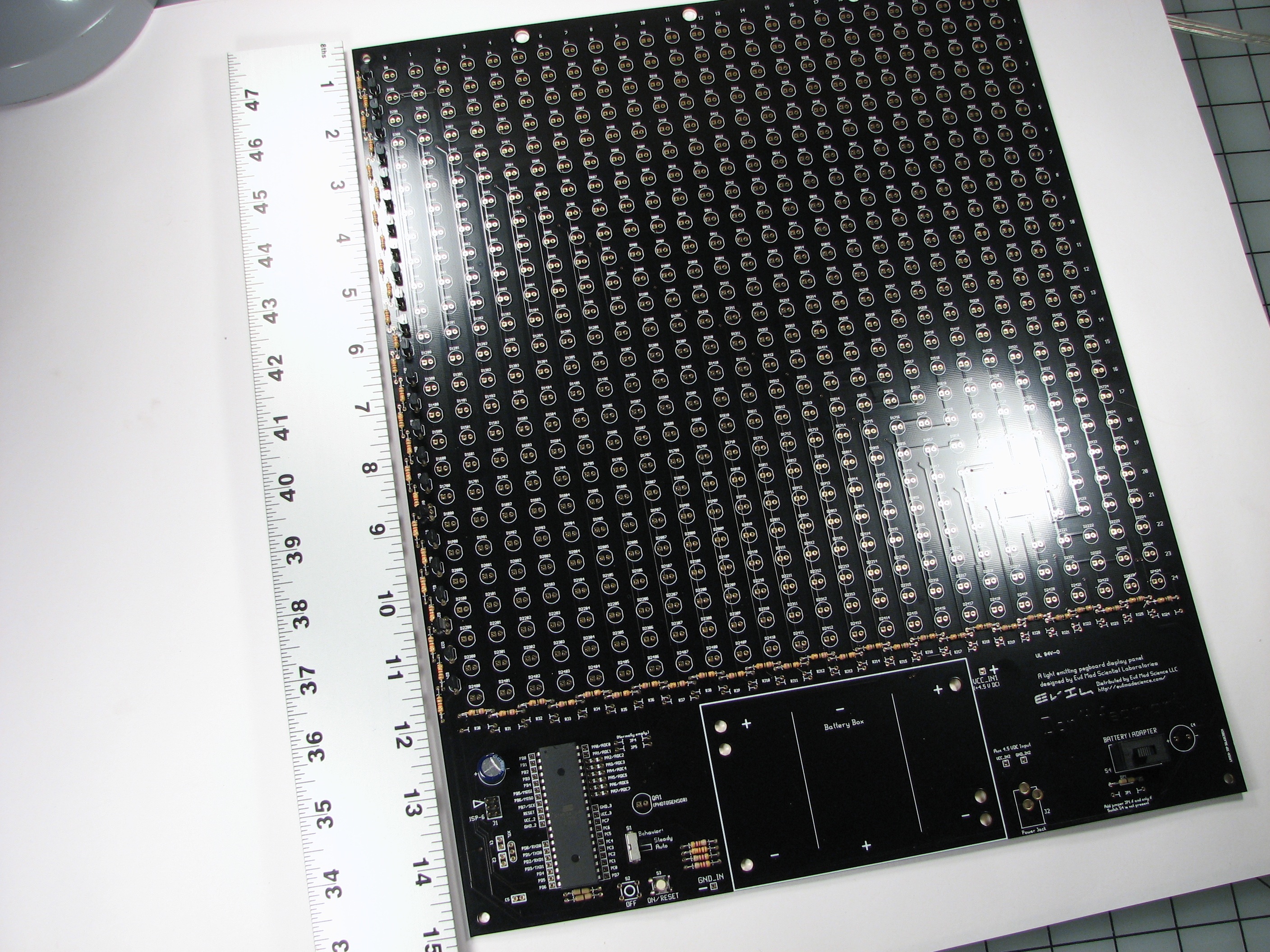
The design is based on a large custom printed circuit board that provides a 25 x 25 grid of locations for LEDs; 625 in all. Around the edges of this array go resistors and transistors that serve to control the array, driven by a large AVR microcontroller. Once those peripheral components around the edges have been added, every one of the 625 LED locations is active, and an LED placed there will light up and be efficiently driven.
Circuit theory
The basic idea is that we have constructed a multiplexed array where only one row of the display is actually turned on at any given time. However, the microcontroller scans through the different rows so quickly that they all appear to be on continuously. The anodes of the LEDs in each column are connected together, and through a single resistor to the positive voltage rail, 4.5 V. Since only one row is ever on at a given time, that column resistor limits the amount of current through just one LED– effectively providing one load resistor for every LED that is on at a given time. The cathodes of the LEDs in each row are connected together and are controlled through a single NPN transistor driven by the microcontroller. This design inherently does not care which LED locations are populated and which are empty– performance is not affected by the number of LEDs in a given row.
Microcontroller
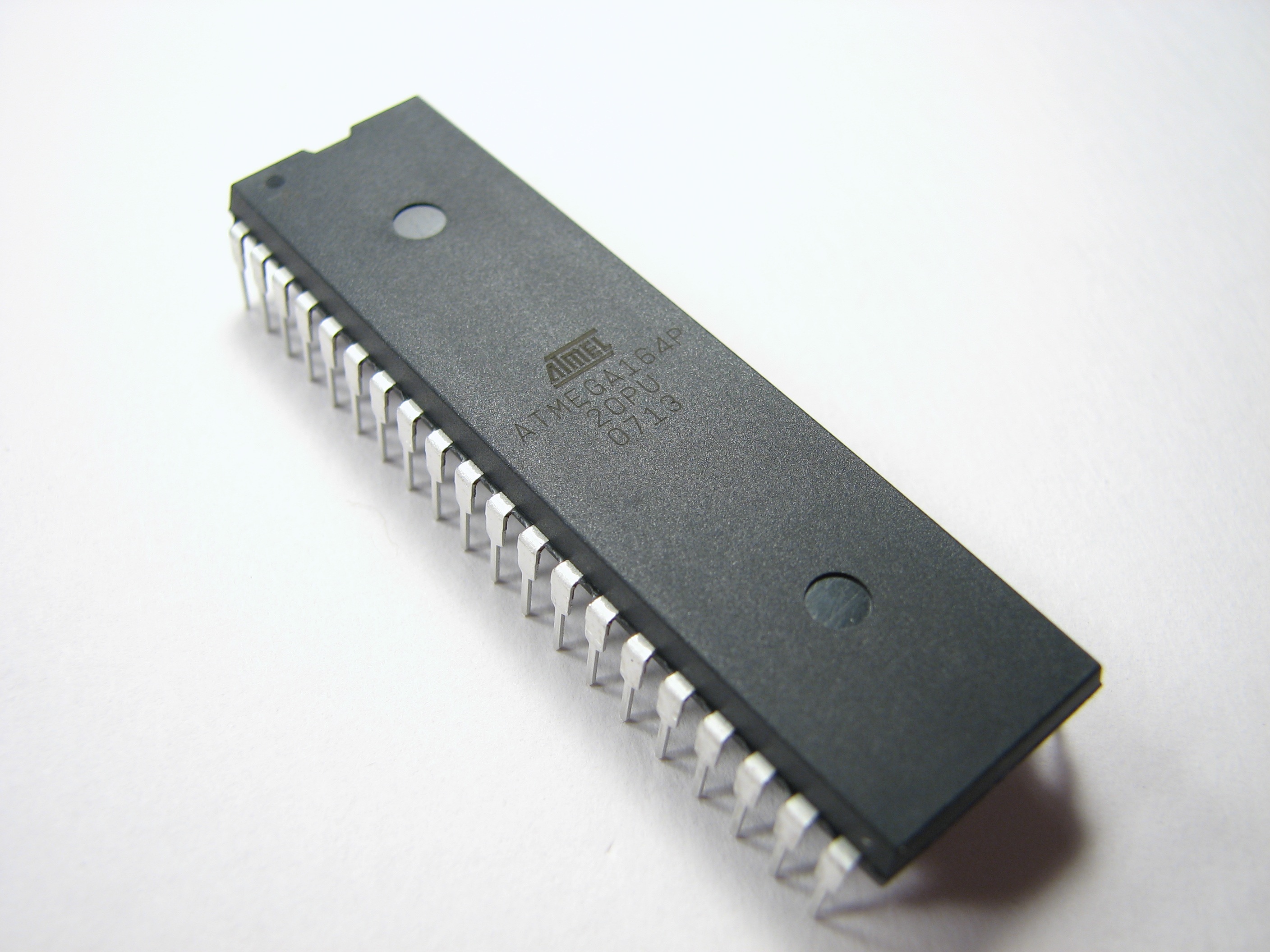
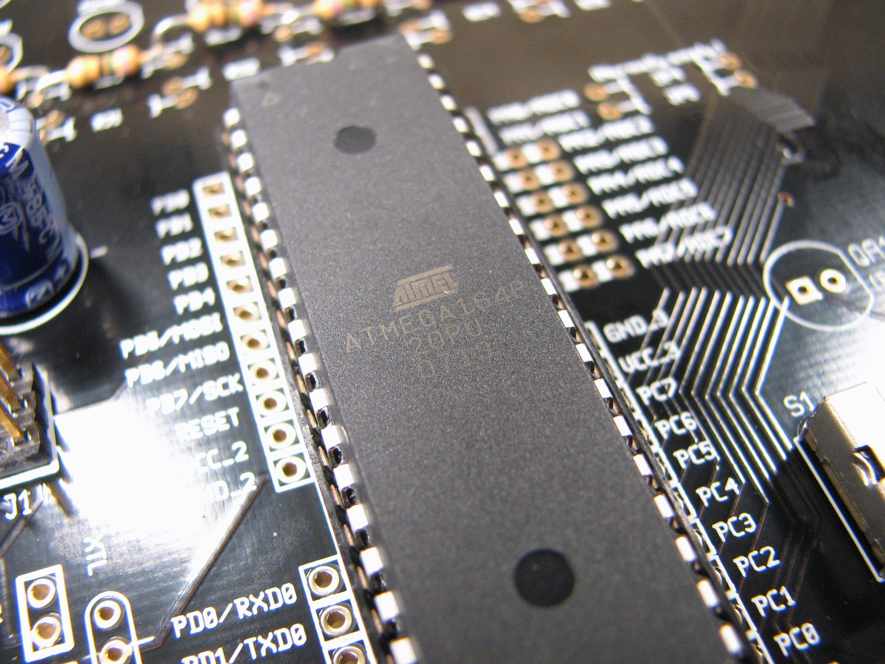
While there are some other ways that the circuit could be driven, we chose to use an ATmega164P microcontroller to drive the display. It is a relatively inexpensive AVR family microcontroller with 16 K of flash, hardly any of which is required for the basic row-scanning functions that we use. The most important thing is that it comes in a 40-pin package that can easily drive the 25 pins of the display and still have room left over for several extra I/O pins including analog to digital converters. One of the main reasons to pick a controller like that is that one of our design goals was for the whole circuit to be seriously hackable. What exactly can be done with that processor and its extra inputs is wide open. As a simple example, our default firmware uses a light sensor and can (optionally) turn off the display during the daytime.
What does it look like?
First of all it should be stressed that the circuit board is huge: 12 x 15″. That’s because we’ve left enough room at each LED location to fit a “10 mm” LED. The pegboard area itself covers nearly a square foot of space. Immediately below the LED field is room for a battery box (3 x D-cell). On the lower left is the microcontroller and on the lower right there is a place for a power jack and a switch to select whether the board is powered from an adapter or from batteries.
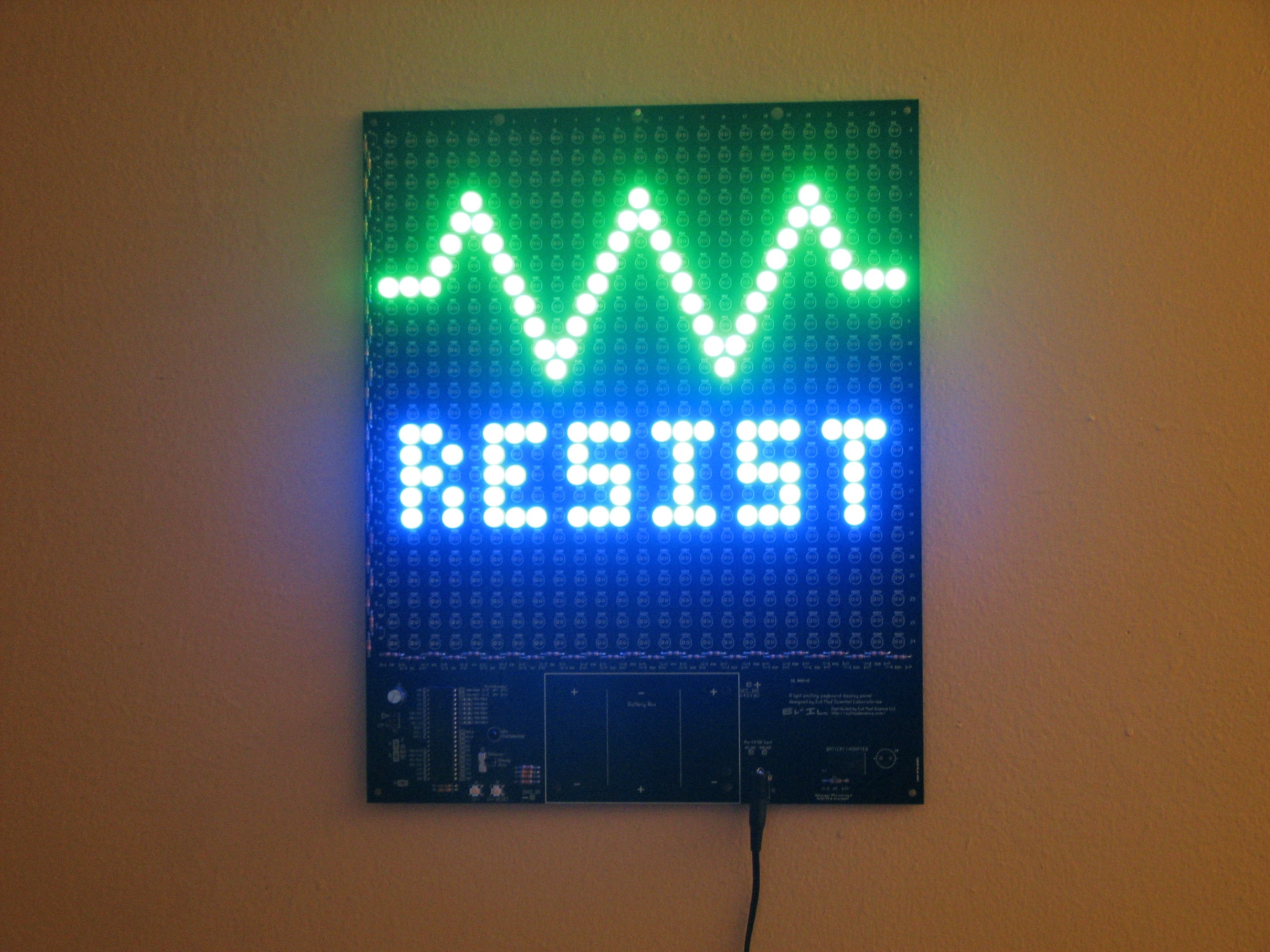
Of course, what we really care about is what it looks like when there are things on the circuit board:


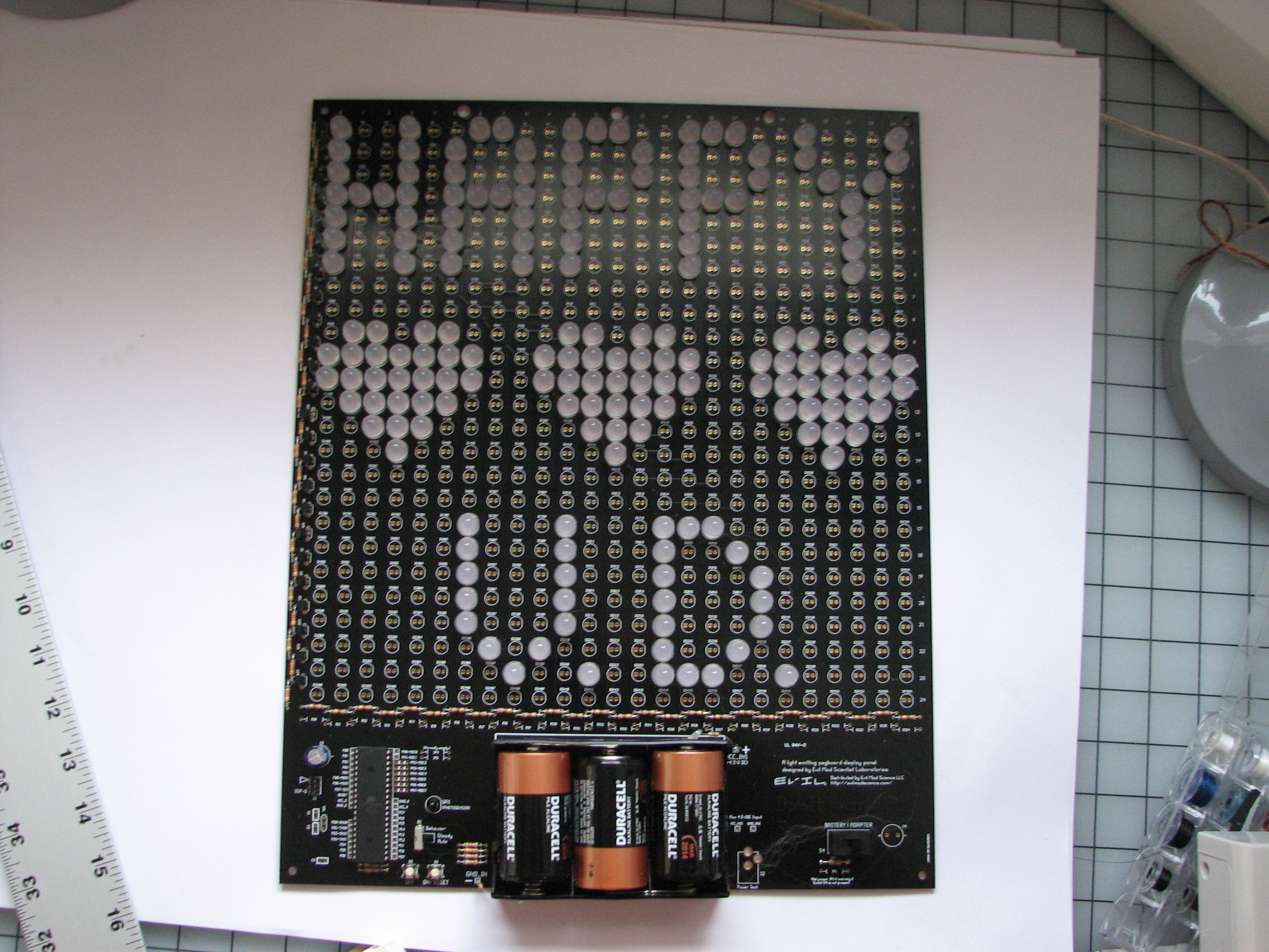
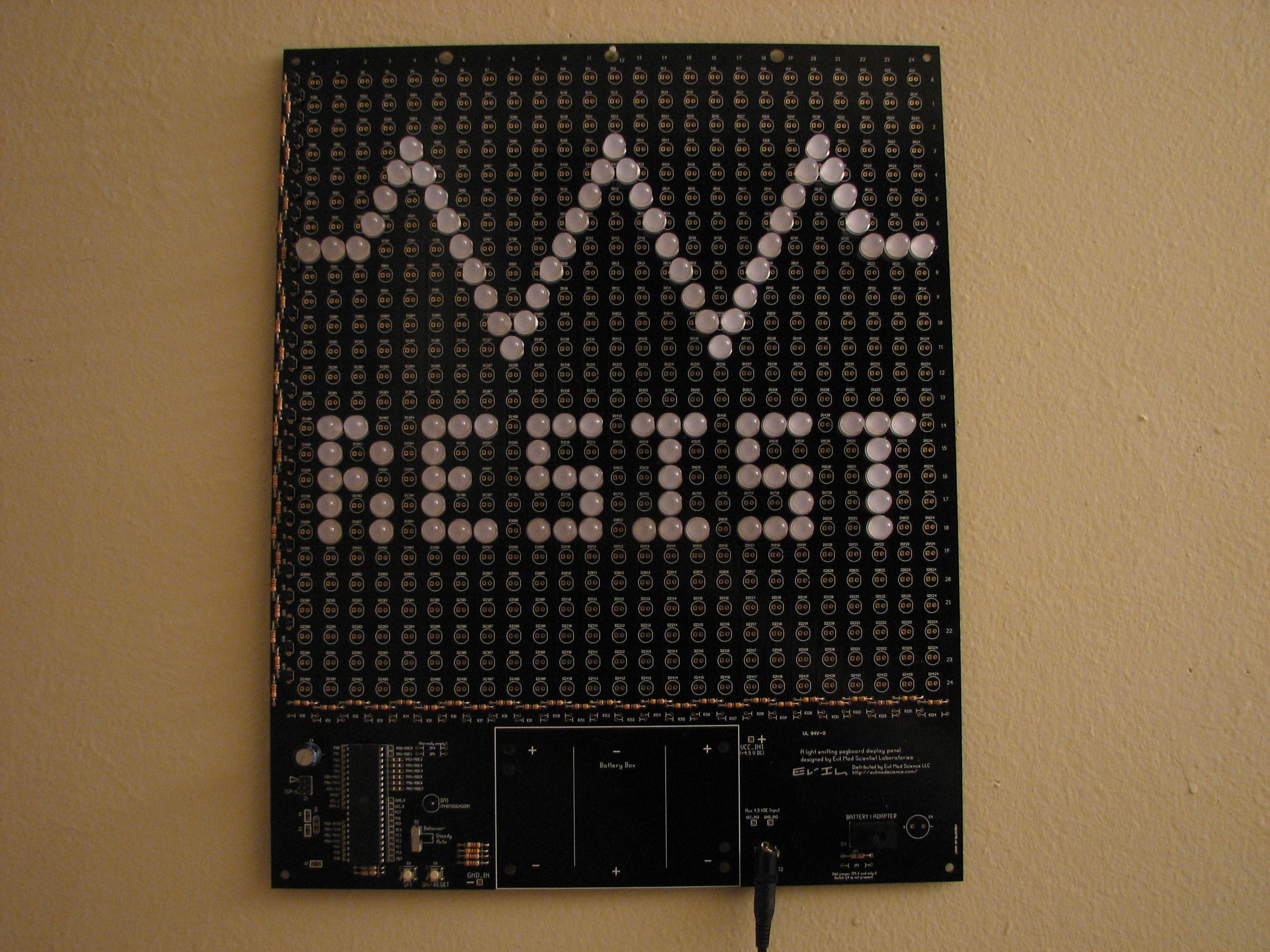

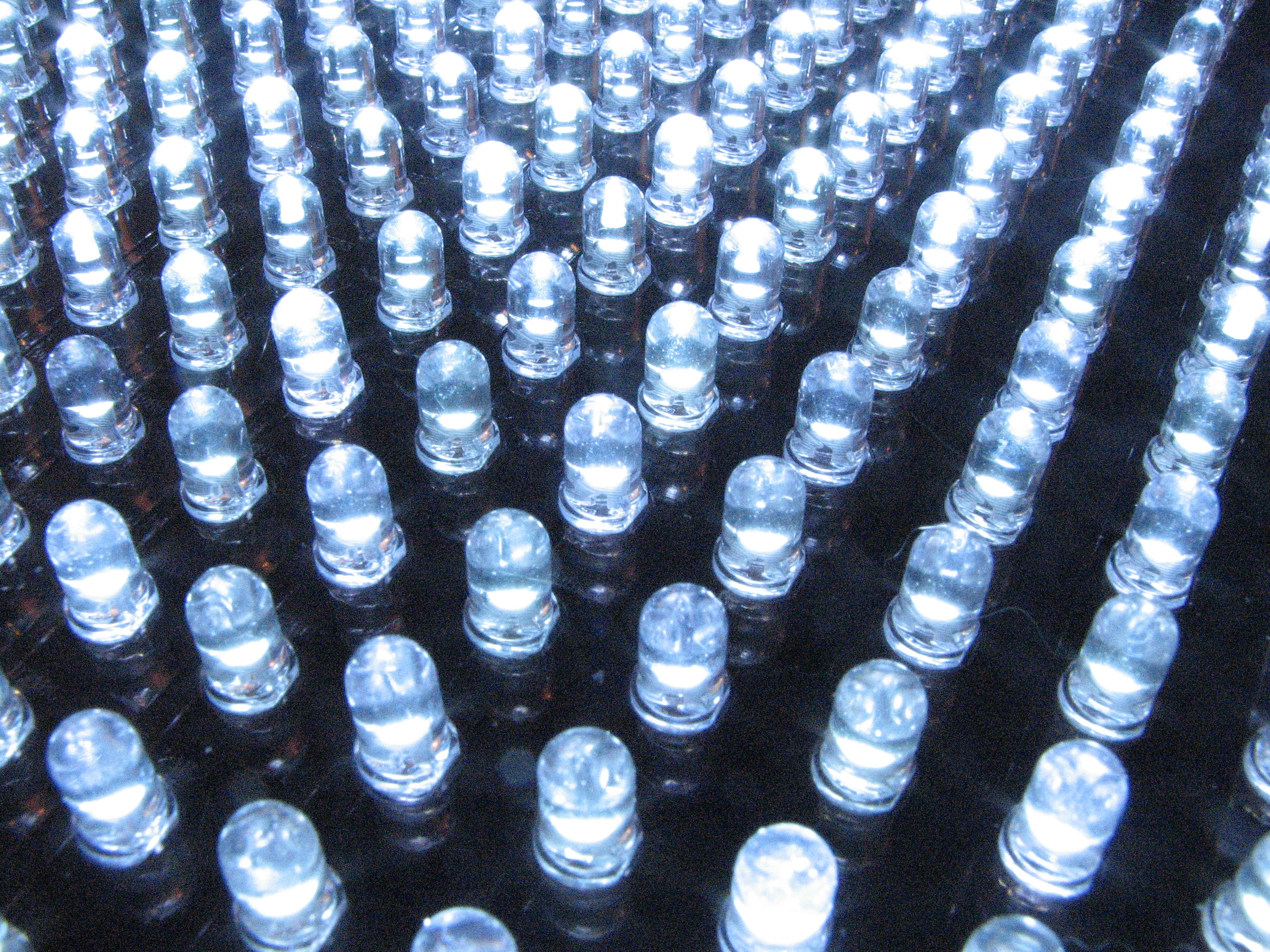

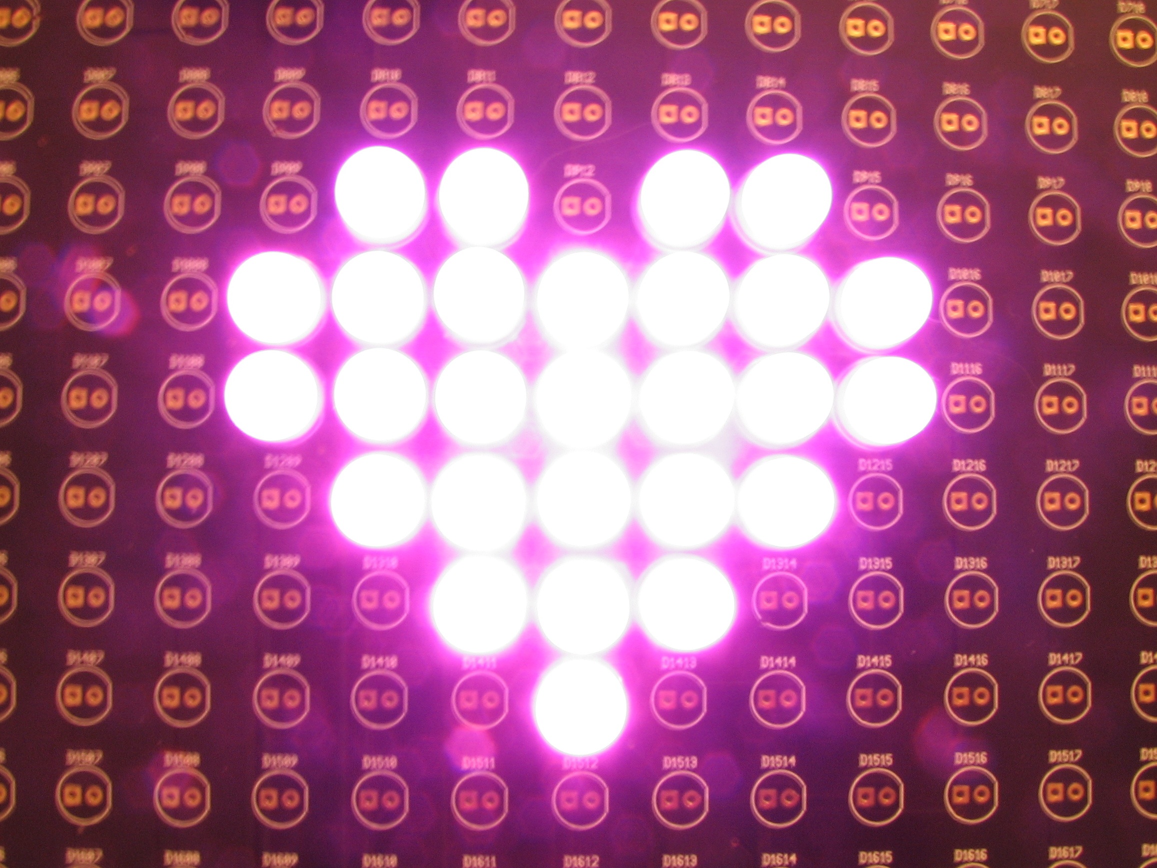

In the examples above, you can see our Evil Mad Scientist “Resist” logo, along with our electronic and sarcastic valentine’s day card. There are also closeups on 10 mm pink, green, and blue diffused LEDs, as well as 5 mm white clear LEDs installed in the panels.
How do you make it?
This project is fully documented, wide open, open source, and you can approach it from any direction you want. Start with the schematics and firmware, or start with a circuit board and a soldering iron. It’s all yours:
- Get a kit here.
- Build instructions and schematics are here (1.7 MB PDF File)
- Download the Bill of Materials (45 kB PDF File), featuring Digi-Key part numbers.
- Thrill at reading the painfully simple GPL-released firmware, written for AVR-GCC. It’s available for download here. (16 kB .ZIP file)
- The circuit board was designed in gEDA PCB, and you can download the original PCB file here; Fundamentally, it’s also source code; we are releasing it under the GPL.
- Want to talk about it? That’s what the forums are for.
FAQ:
1. What’s this all about?
This is an easy way to drive a lot of LEDs– up to 625– in a big matrix. You can make an LED sign for your window, a geeky valentine for your sweetie, one bad-ass birthday card, or freak the holy bejesus out of Boston. Your call. It’s a versatile, high-brightness display.
The display can run off an AC adapter or batteries (3 ‘D’ cells), and is designed to run as many green/blue/white/violet LEDs as you care to solder into the holes, all with excellent brightness. The board can accommodate LEDs in several common sizes: 3mm, 5 mm (standard T-1 3/4 size), and 10 mm. A photosensor is provided that can automatically turn off the display in bright daylight or incandescent light.
2. Do I have to put the LEDs on the grid, or can I position them exactly where I want to?
You do not have to place every LED on a regular grid. See the instructions for some tips on how to position the LEDs more arbitrarily.
3. What can I reprogram the display to do?
If you have an appropriate interface and like to program, you can control what the display does, either turning all the LEDs on and off, or controlling the individual rows (but not columns) of the display. Here are some basic ideas to get you started:
- Turn on only for a given period of time after it goes dark, or even after a given period of time.
- Blink or flash the whole display slowly or occasionally. Use it as a strobe?
- Add external buttons to control the display.
- Make an insane-o-tv-b-gone? (Yes you can!)
- Use the photosensor to make the display interactive in other ways– turns on for ten seconds when somebody walks by?
- Make an open/closed sign where either the top half or the bottom half of the display is on.
- Make a sign with a static logo in one half and blinking text in the other.
- Animate vertical waves, fading in and out through the display.
- Put different color LEDs in different rows, and alternate how much each of them is driven to make a color changing illumination panel, or a static panel with adjustable color.
- LED coffee table?
- 8-bit style electronic art for your wall or bicycle– it can run on batteries, you know.
- LED illumination panel for photography or even an infrared illumination panel.
- Use the light sensor, or other sensor with the analog inputs and make a scrolling strip chart that records and displays the history of that variable, plotted by the intensity of the rows of the display.
- Attach a sound sensor and make a display or sign that pulses to the beat.
4. What is the “charlieplexing” option/hack?
It’s an alternate configuration (well, a hack, actually) for the board that allows you to control individual LED locations to a limited extent. It requires you to change the hardware around a bit and reprogram the board. It is much dimmer, and doesn’t have enough speed to do anything really complicated. There are also some bugs to work out (A hack with bugs? Never!) that may not make it impossible– or at least very inconvenient– to drive a board that has a lot (note: purposefully left vague) of LEDs on it. So what *can* it do? It can allow very minor animation in limited cases– do you want to blink or wink the eyes on your giant happy face display?
4A. Do you recommend building the multiplexed (standard) or charlieplexed display option?
For almost everyone, the standard option is the way to go. It’s much brighter.
4B. Can I put in 625 LEDs and use this as a full animated display with charlieplexing?
It’s probably possible, but we don’t recommend trying that yet– again, there are some bugs to work out first, and we may need a more severe hack to make it work well.
Update: We released Peggy 2.0 in May 2008.
Very cool! I have to say though that "Happy V.D." took me a second to get the intended meaning.
Brilliant!
Is V.D. the gift that keeps on giving?
V.D. is.. ambiguous.
hopefully intentionally so.
The per character humor density is quite high.
—
Windell H. Oskay
drwho(at)evilmadscientist.com
http://www.evilmadscientist.com/
How hard would it be to solder LED sockets to the board, so that one could swap LEDs at any time?
About as hard as soldering the LEDs would be, along with the added effort of trimming the LED leads if you wanted them to fit flush against the sockets.
Still, it’s a good idea, and sockets ARE cheap enough in bulk.
Yeah, I’d like to see a version that used LED sockets. Preferably strip-type sockets that take multiple LEDs, to keep things sane.
This project is meant to take some of the pain out of driving LEDs– making something that’s easy to reconfigure as well is a somewhat different goal. It could certainly be done by adding sockets to a board like this, but it would really make this a much bigger project. There are two nice things about just using the solder holes like we have. First, these holes are pretty easily mass produced in the board assembly process– it only adds a few dollars per board to have that many holes drilled. Secondly, you don’t have to fill every hole with a connector– that *really* cuts down on assembly time.
There are some fine sockets that could be used if the board were redesigned with slightly larger holes– that part would be relatively easy. Then we just add some single-pin sockets. Specifications needed: Spring loaded to hold LED pins from 0.020" – 0.025", with gold plating for reliable long-term contact without soldering the LEDs in. I found some suitable ones that only cost $0.11 each when purchased by the 10,000– actually an okay price for things like that. But, there are 625 holes, so 1250 sockets are needed, which increases the cost of the *parts* for the kit by $137.50, meaning that the kit price would have to go from $80 to about $250. Also, the assembly time for the board goes from about one hour to about 6-7 hours. (Minor details…)
Rather than doing it "right," you could instead consider using parts of cheap DIP sockets instead, or possibly add parts of solderless breadboards. It would be an ugly mess, but ought to bring the added cost down to about $50 extra and 4-5 hours. You’re welcome to do that on your own– but it won’t be part of our kits any time soon.
—
Windell H. Oskay
drwho(at)evilmadscientist.com
http://www.evilmadscientist.com/
Exactly what I wanted to know, thanks!
You know, you don’t really need a socket for every possible position right away. For the first effort, you solder in the sockets for the LEDs used by your first picture; it takes about the same amount of time as soldering in the LEDs (plus the time to install the LEDs into the sockets.) Poof; done. Now your project sits around for a few months, or years, and you decide it’s time for a new picture. So you pull the LEDs out of the sockets, figure out where they’ll go next, and solder sockets into just those places that don’t already have sockets; again, this isn’t much more difficult than creating a new board. Repeat as needed, buying more sockets as necessary; eventually the whole matrix will have sockets, and each picture will only take a maximum of the number of LEDs in THAT picture.
What you need is a cheap ugly socket that can mount on the backside of the board, probably using an extra set of pads, so the LED legs can go through the normal mounting holes and into the socket. No ideas there :-(
This is very cool. It occurs to me that rapidly moving bars of light could be used to make a Dreamachine, which usually uses a record player to produce a flickering pattern of light at around the rate of alpha brain waves. The dreamachine is said to induce fantastic visual illusion — http://en.wikipedia.org/wiki/Dreamachine.
To make a dreamachine would, of course, take some programming. I’ve programmed an Arduino but I don’t have much experience with programming in C and would prefer to avoid the hassle of learning. Could the chip be programmed on an Arduino board and then moved over to the Peggy. I suspect not but perhaps someone could suggest a way.
What a good idea. Perhaps the next run of boards should do the silkscreen in a more subtle color? (Hmm. Do silkscreens COME in subtle colors?)
Yes, it is a pretty bright silkscreen. It’s a mixed blessing– it makes the assembly easier, but gives some background noise. Red silkscreen is available too, so we could try that in the future… our “EVIL” logo would look pretty good!
One of the hints that we include in the instructions is that you can actually build it with all the LEDs coming in from the backside of the board, where there’s no silkscreen– for a seriously black board. One pad is a square and one is a circle, so you can still tell which way to put each one in.
—
Windell H. Oskay
drwho(at)evilmadscientist.com
http://www.evilmadscientist.com/
I am not usually one for special occasions, so it took me some time to understand what VD was referring to; but I expect it has very high humor density for character.
Kevin
LANL
ps Nice board.
pps I only give people gifts if they contain LED’s…hopefully the light will bring them illumination (in more ways than one).
>I only give people gifts if they contain LED’s
Hi Kevin,
Excellent policy!
—
Windell H. Oskay
drwho(at)evilmadscientist.com
http://www.evilmadscientist.com/
I am a bit confused, have looked at the schematics but still do not quite get what is going on. Normally I would expect to get full row and column control over a 25 by 25 array you would need 25 + 25 port bits or a trick. Could you explain just a bit more?
As we discuss above, this particular board is not really intended for animation– it’s principally a static display. Reprogramming it, it’s also easy to blink or get full grayscale control of the display as a whole or by one row at a time.
Finally, if you want to go beyond what the supported features of the board are, you *can* hack it to be a "charlieplexed" display (look that up) where every LED is individually addressable. (The trick is that every I/O line from the microcontroller is tristateable….)
—
Windell H. Oskay
drwho(at)evilmadscientist.com
http://www.evilmadscientist.com/
your missus gave you a vd?
can i control single LED through above circuit
rajasekaran
I am trying to construct a frequency independent light display and i need all the help that i can get. my email is vikisy_org@yahoo.com