


You’ve got your components, and your datasheet, and you’re read to start hacking. But which way does the chip go? Pin 23 is where? If you’re lucky, the orientation is clearly marked, or perhaps diagrammed in the datasheet. But if it isn’t, or if you’re simply new at this, it’s helpful to know what to look for.
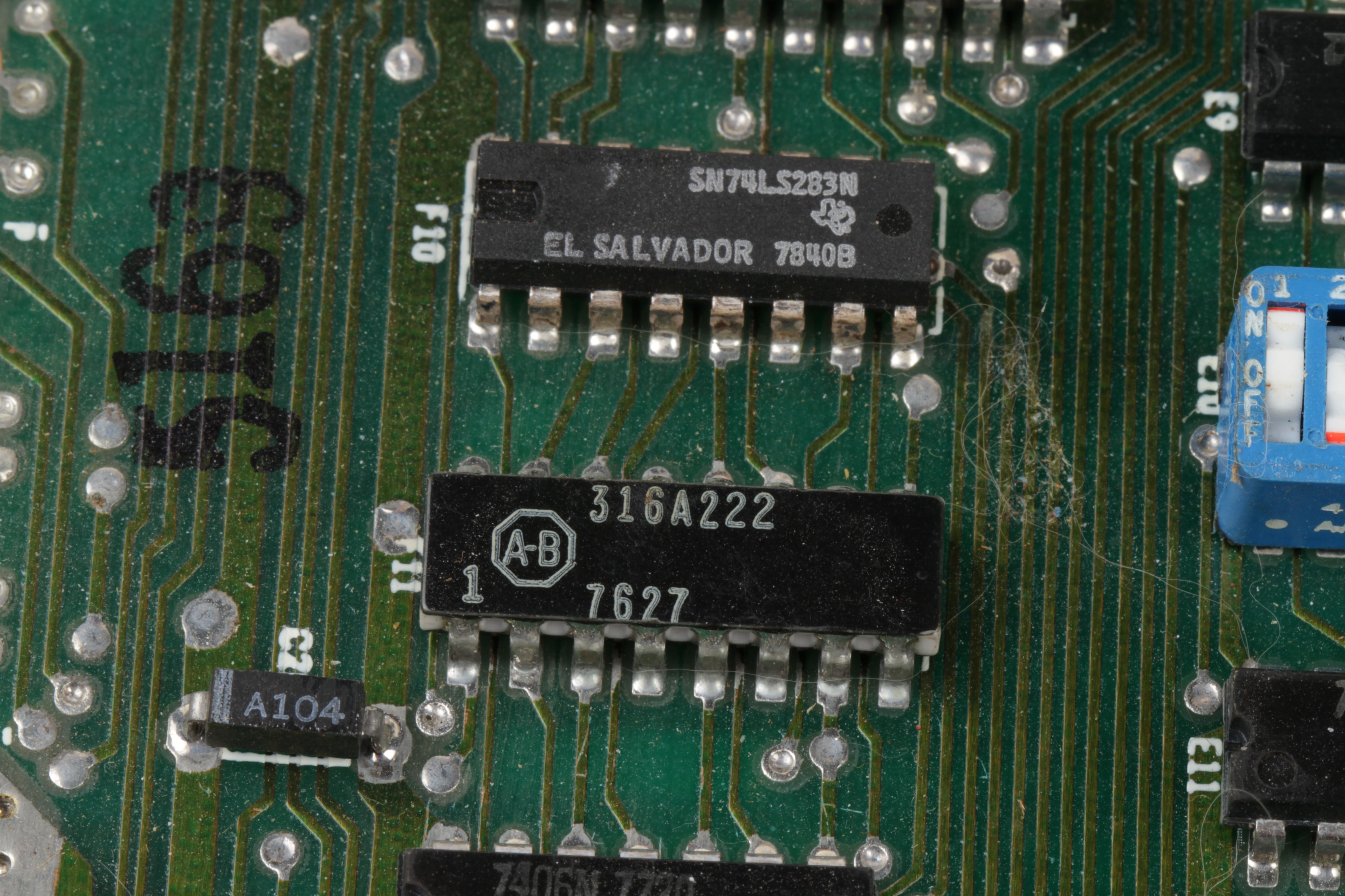
In the picture above, pin 1 is clearlymarked on the Allen-Bradley resistor pack. And for better or worse, this is the exception, not the rule.
Here is a basic rule that applies for mostintegrated circuits: There’s a polarity mark somewhere. From that polarity mark, move counterclockwise around the chip, and number the pins starting at 1.
A common polarity marker is a half-moon shape at one end of the chip. Another is a small dot by pin 1, or sometimes a small triangle or tab instead. Sometimes several of these marks can appear.
Often pin 1 is in a corner of the chip, and it’s only that corner— not the pin itself –that is marked by the small circle or triangle.
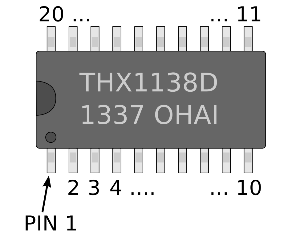
In this sketch, we’ve drawn an imaginary part number “THX1138D,” manufactured in week 37 of 2013, and it has a mysterious lot or internal code “OHAI” that may or may not be explained in the datasheet. The polarity marks are a half-moon indentation on the left hand side as well as a dot by pin 1. This device has 20 pins, numbered counterclockwise along the two edges from 1 to 20.
As we’ll see, there are plenty of examples of this, or close variations on it. But there are also cases where there are *no* direct marks, but you can instead rely on the orientation of the text to understand the numbering. The text orientation is consistent, and for chips of this shape (with pins on two opposite sides), you can reliably assume that the polarity mark goes to the left of the text.
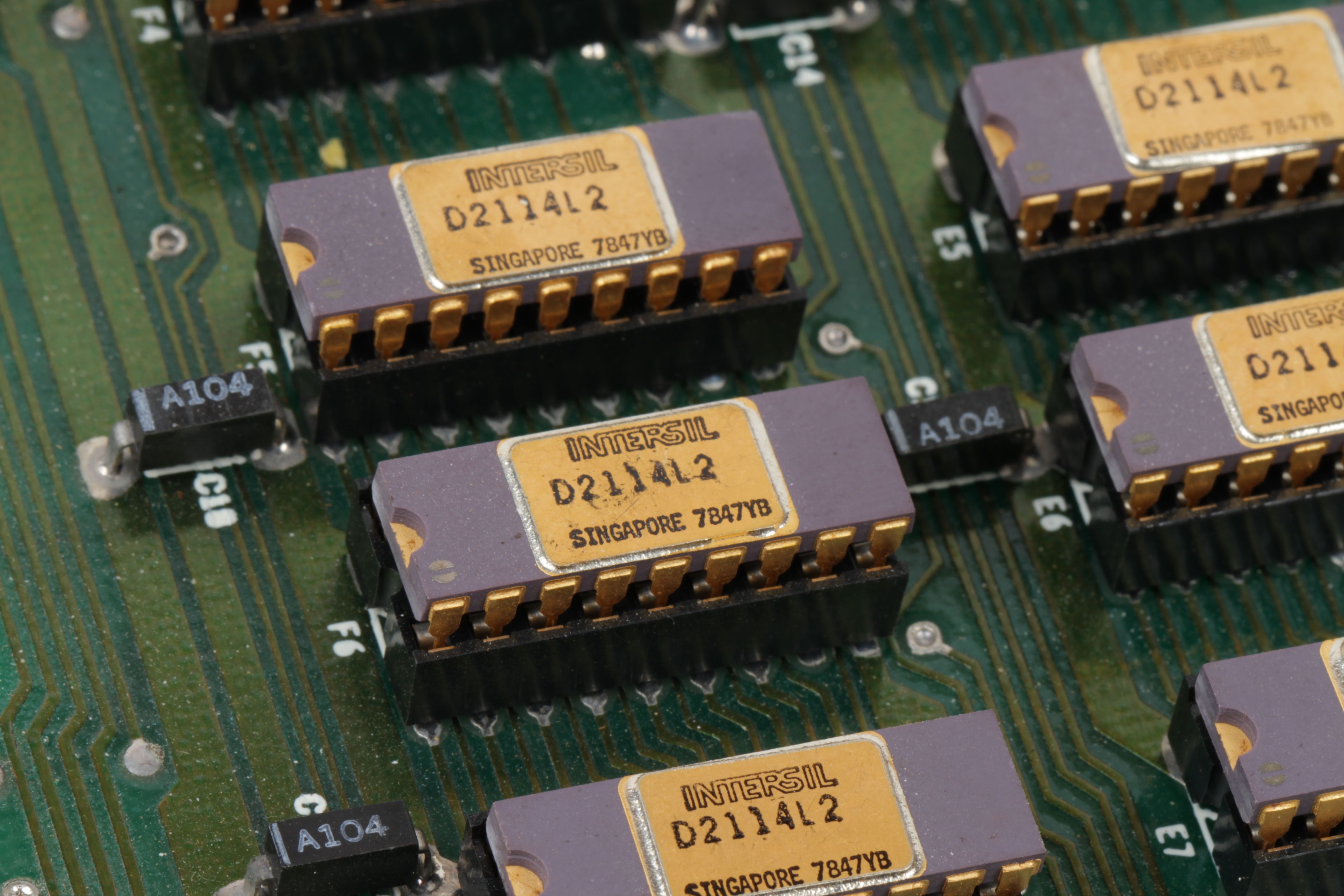
Here are some classic and beautiful examples of chips with well-marked polarity. These are “ceramic DIP” integrated circuit packages, dated from the end of 1978. Each has a molded half-moon shape as well as a more subtle dot by pin 1.
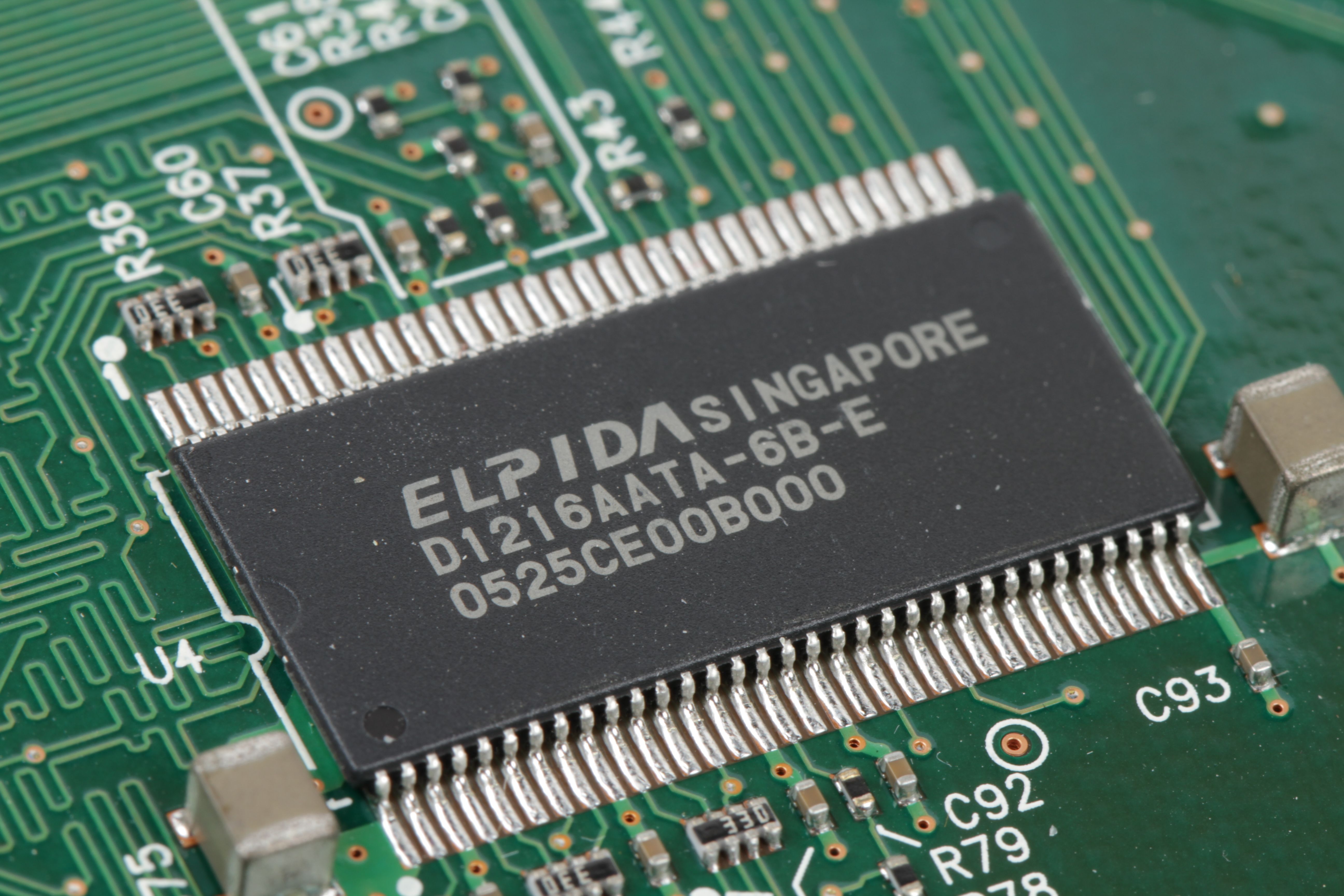
This is a modern higher-density variation on the same design. It’s a wide, low-profile plastic package called a 66-pin TSSOP (and a 128M bit DDR SDRAM, if you’re curious). The orientation is given by the half-moon shape on the left hand side and by the dot in the lower left corner. Now, that dot actually looks like it’s closer to pin 2 than to pin 1– Again, the marker often labels the corner where pin 1 lives, not the individual pin.
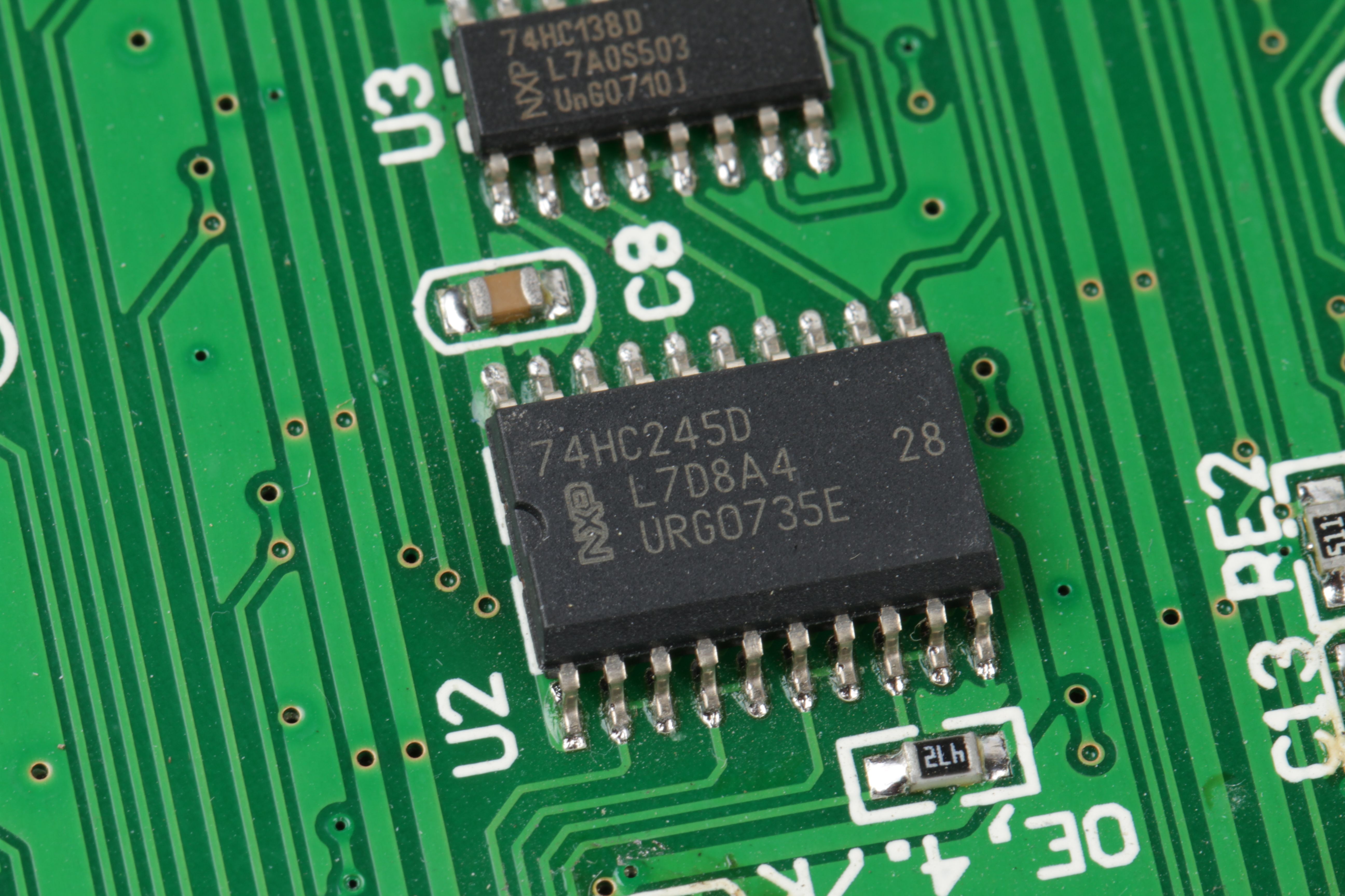
This 74HC245D “octal bus transceiver” chip from NXP has the half-moon shape on the left hand side, plus a slightly more unusual polarity marking feature. The entire front edge of the chip– the edge containing pin 1 –is slightly beveled.
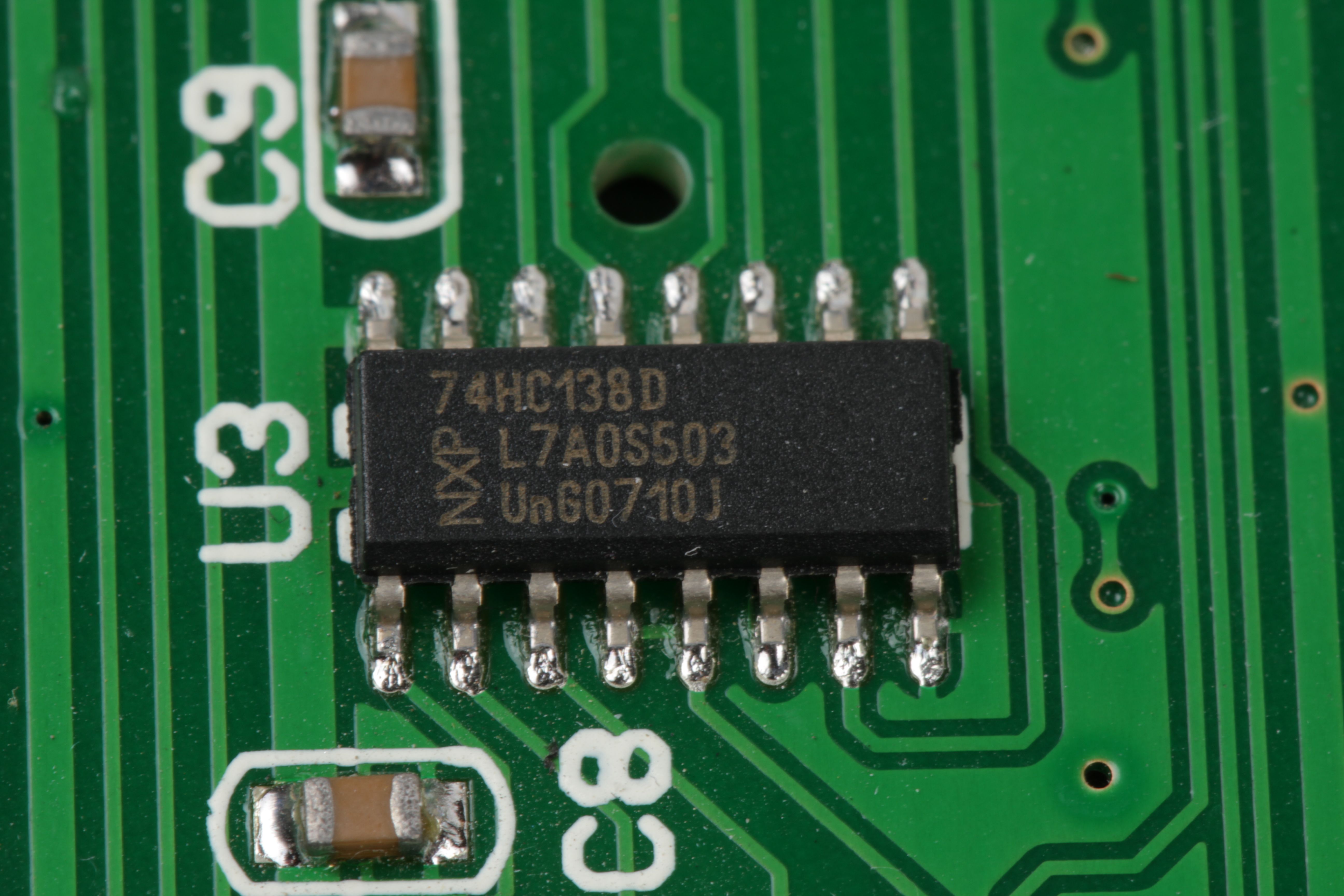
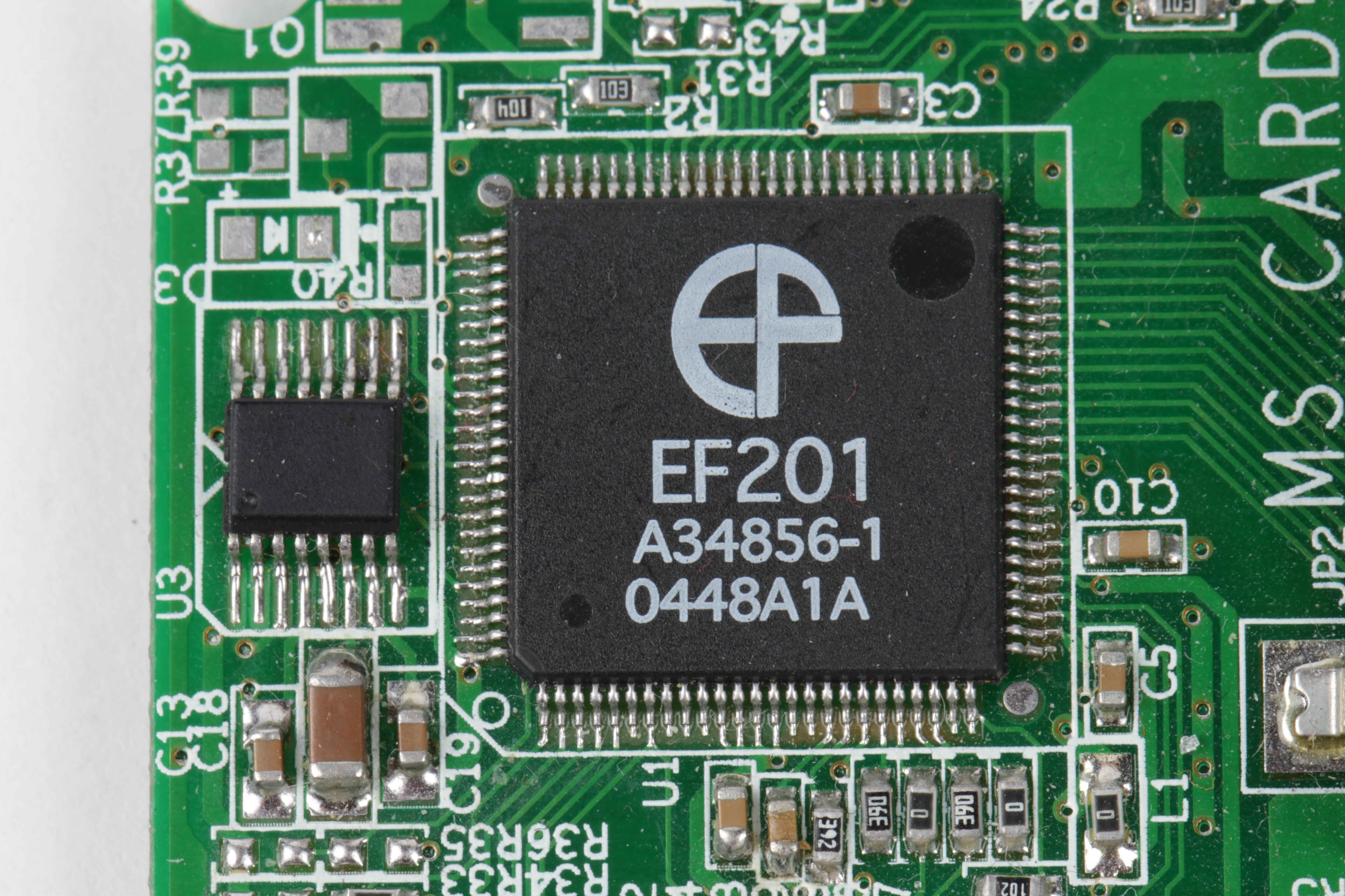
And now here is a chip that has less of a “direct” indication of its orientations– no dot or half-moon shape. As we discussed earlier, you can rely on the orientation of the text in cases like this, and imagine an effective polarity mark on the left hand side of the chip. Pin 1 is on the lower left hand side.
If you look very closely, you’ll see that there is one additional polarity marking feature, in that this chip also has a very slightly beveled front edge.
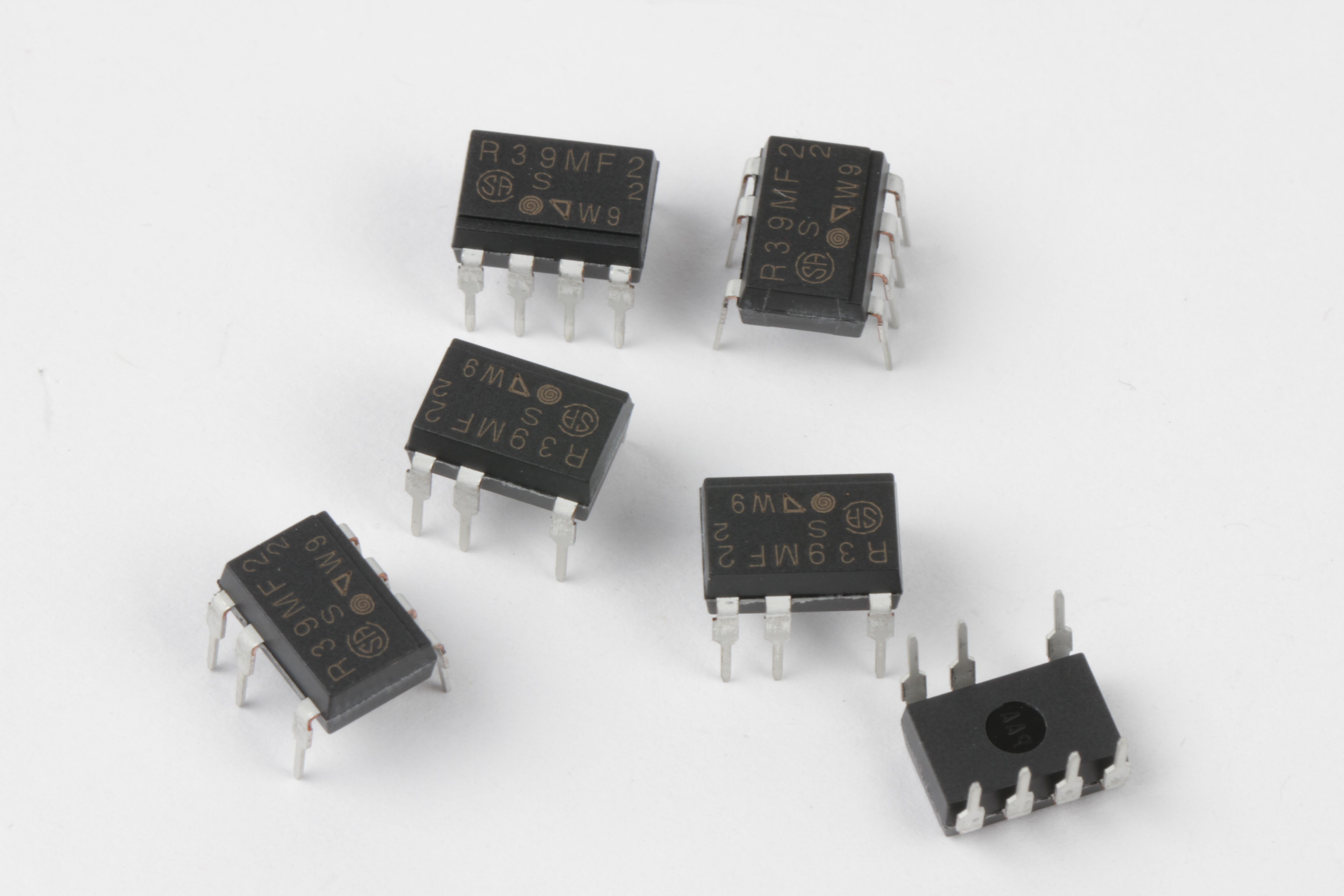
This is a somewhat unusual seven-yes-seven pin DIP chip. It’s a neat little solid-state relay capable of switching small loads on AC line voltage (0.9 A at up to 240 VAC) from a low-voltage digital input. Presumably, it has seven pins so that you can’t put it in backwards. This chip also relies on a combination of text orientation and a bevel at the side with pin 1.
Careful: That apparent “dot” is not a polarity indicator; pin 1 is still at the corner of the chip.
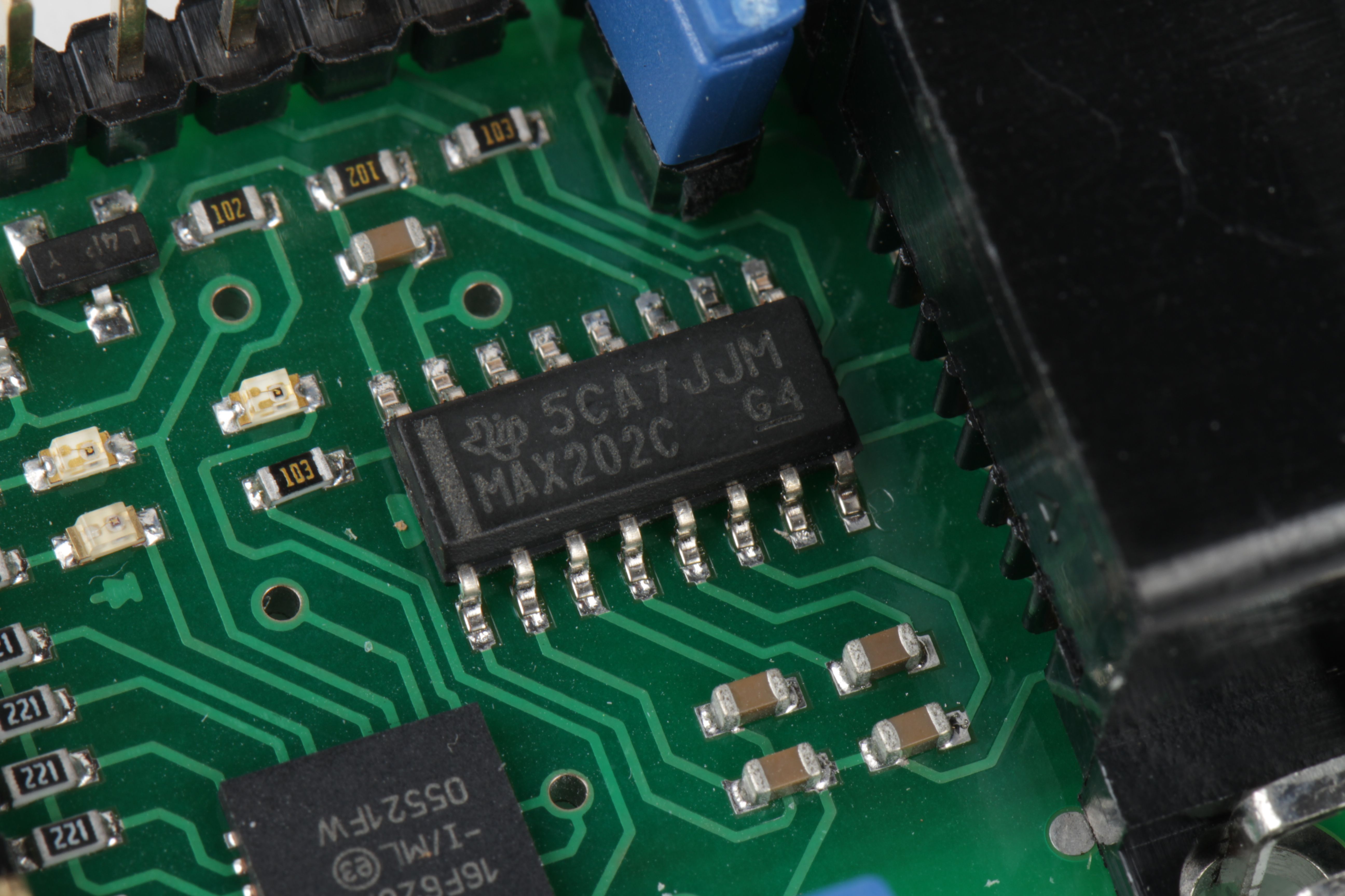
Here’s one more variation. There’s a printed bar on the left hand side of this chip to act as a polarity indicator, taking the place of the half-moon shape.
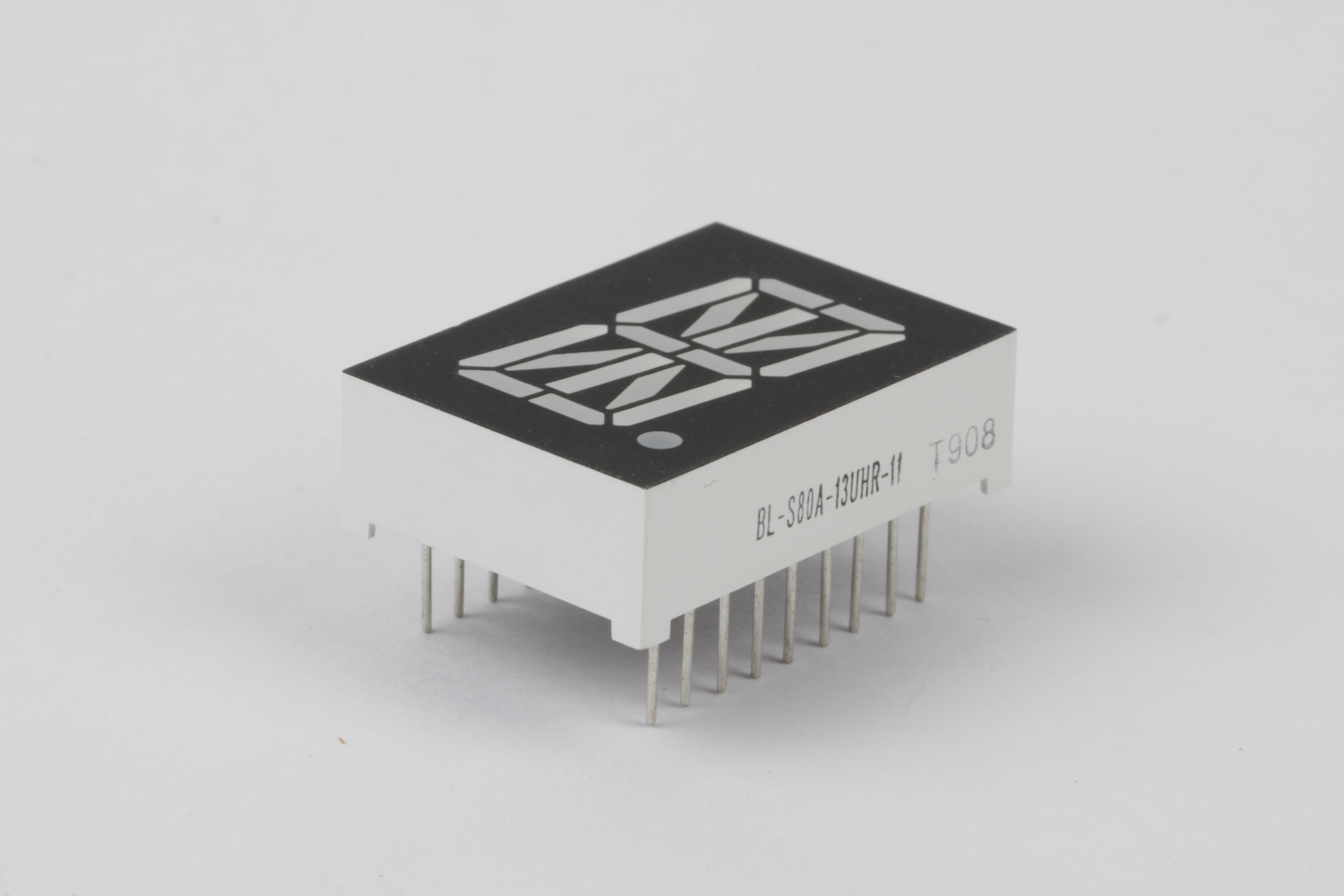
Here’s one that we get asked about quite often: A 17-segment alphanumeric display. LED displays can be pretty baffling, because the pin 1 location is not explicitly marked, and there’s no half-moon shape or other obvious polarity marker. However, the label itselfis a polarity marker and it’s important to remember that.
Edit: We initially had written down that these follow the label-orientation rule, but that turns out not to be the case. While you’d normally expect that the pin to the left of the label would start at pin 1, this device (and apparently some other alphanumeric/7-segment displays) follows a convention where pin 1 is in the upper left of the display– opposite the decimal point. That’s a big “+1” for checking the datasheet!

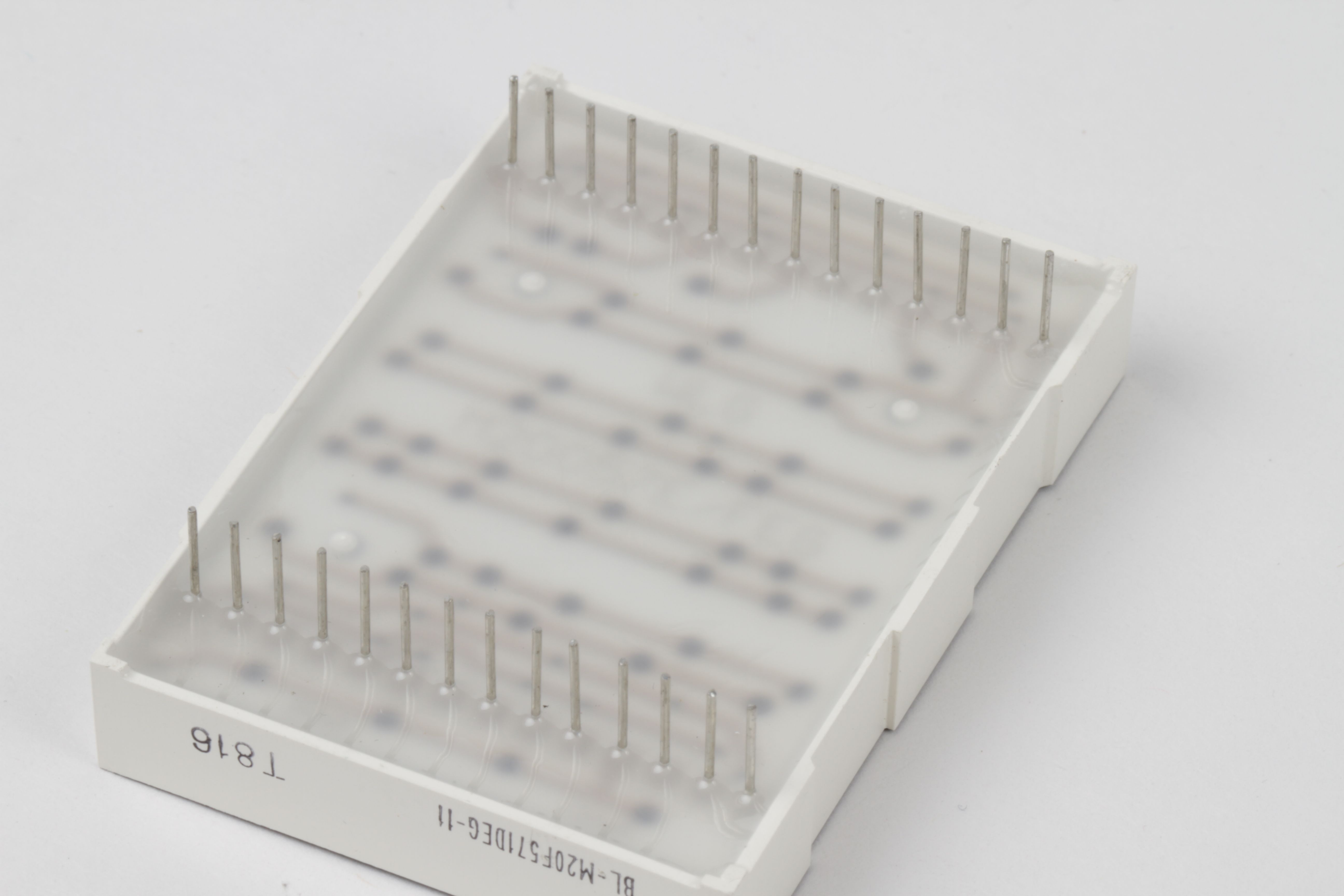
Here’s a 5×7 LED matrix display. You can sort of make out marks on the back side beneath the epoxy, so it’s tempting to look for orientation hints there, but these types do normally follow the label-orientation rule. When you orient the part such that you can read the label, the effective polarity mark is on the left-hand side.
In the left photo, where the display is upright and the label is visible, pin 1 is beneath the lower-left corner. In the right photo, where the label is visible but the part is upside down, pin 1 is visible on the lower-right hand corner.
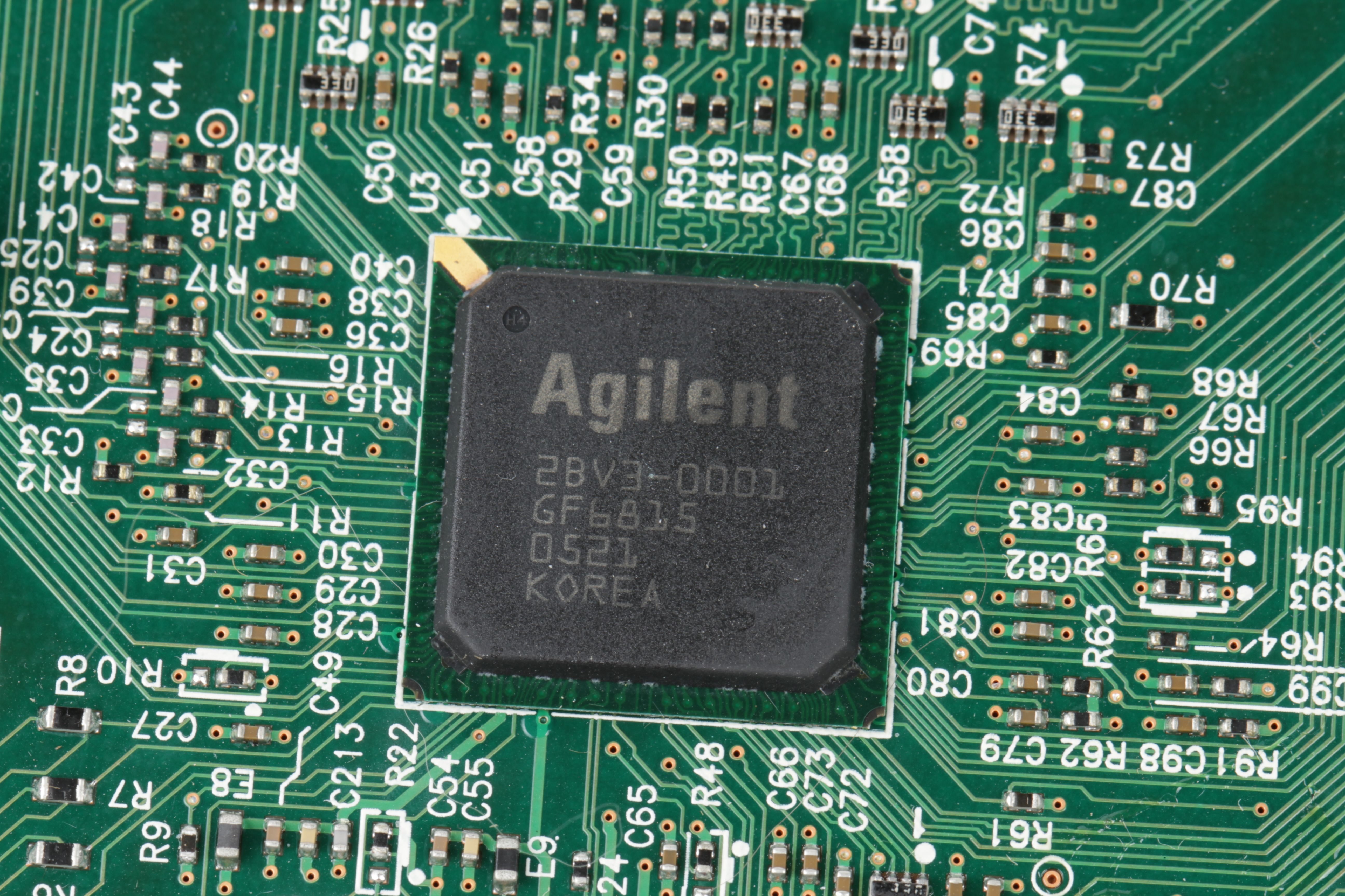
Sometimes you’ll come across very different looking chips with very obvious polarity markers. This chip from Agilent has a gold stripe on the upper left hand corner.
Sometimes a chip has a notched corner to indicate where pin 1 lives. The white silkscreen on the circuit board shows an exaggerated picture of this notching, by the lower-left corner.
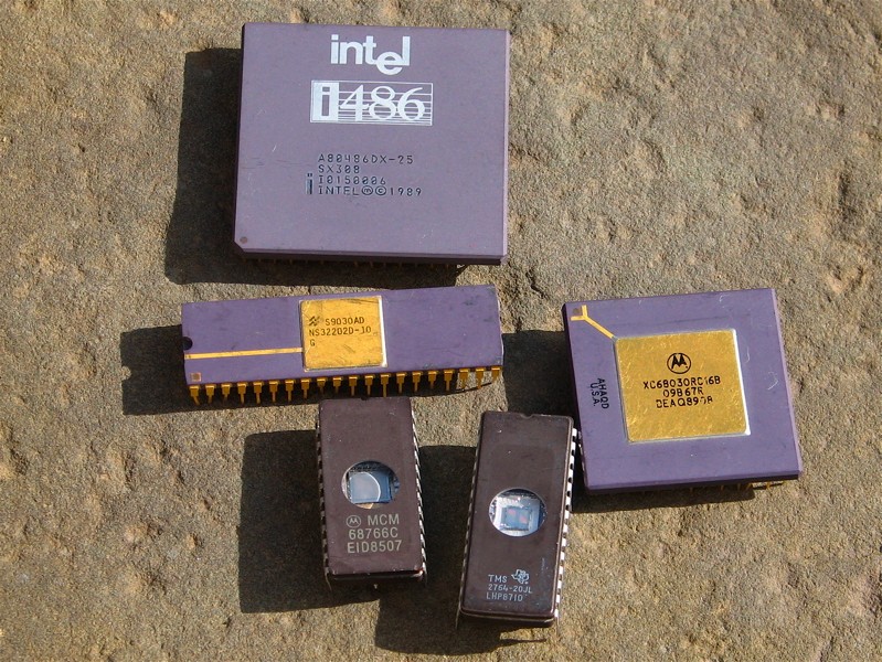
The 486 is a good example of a chip with a notched corner, while the 68030 has a gold stripe to indicate pin 1.
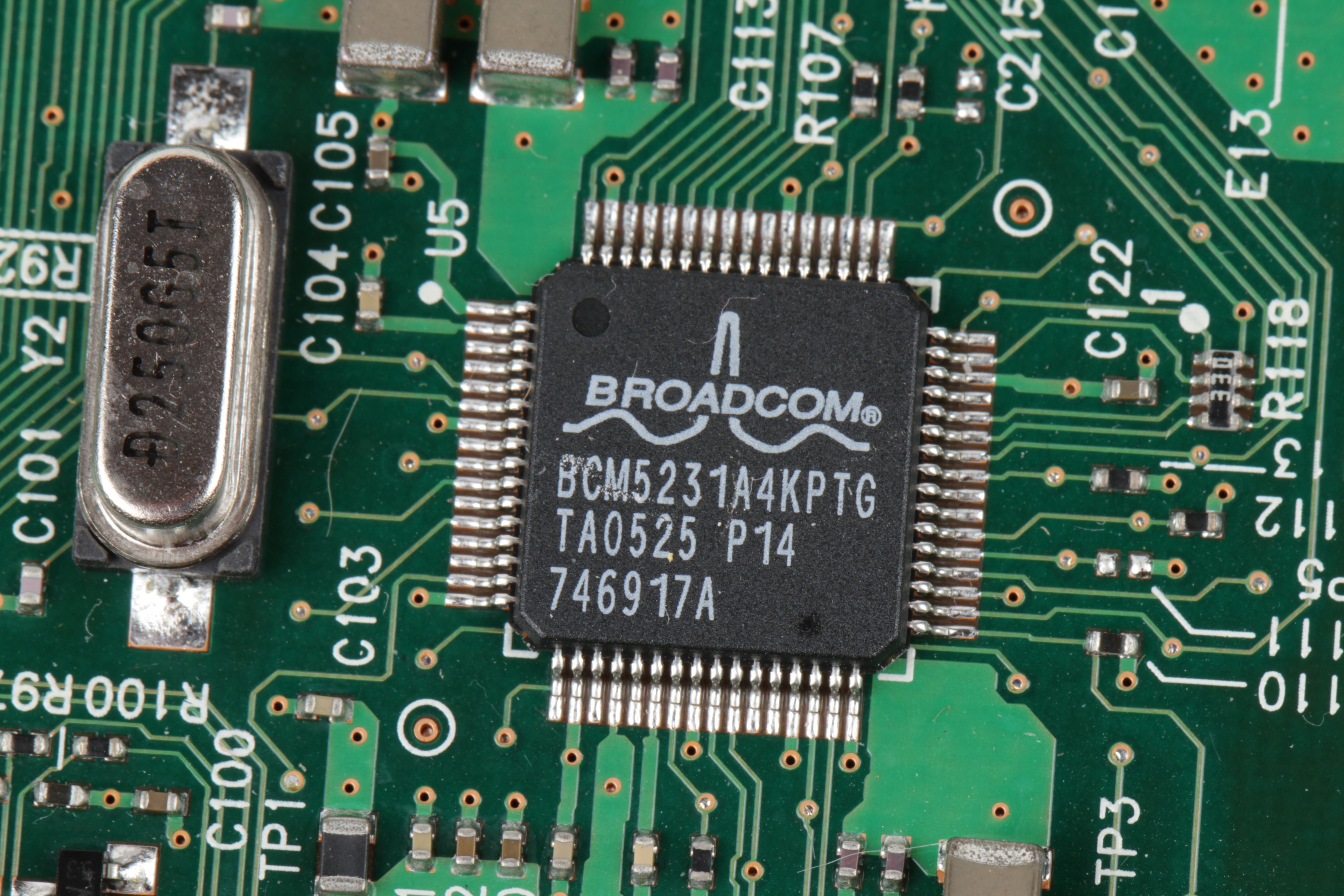
This Broadcom chip has a dot by the corner with pin 1, but that’s a pretty subtle mark. If your chip is already mounted to a board, that can provide some better information to verify the orientation. For example, pin 1 of this chip is also marked by a white dot on the circuit board, and the other three corners have a mark, as though those corners were un-notched.
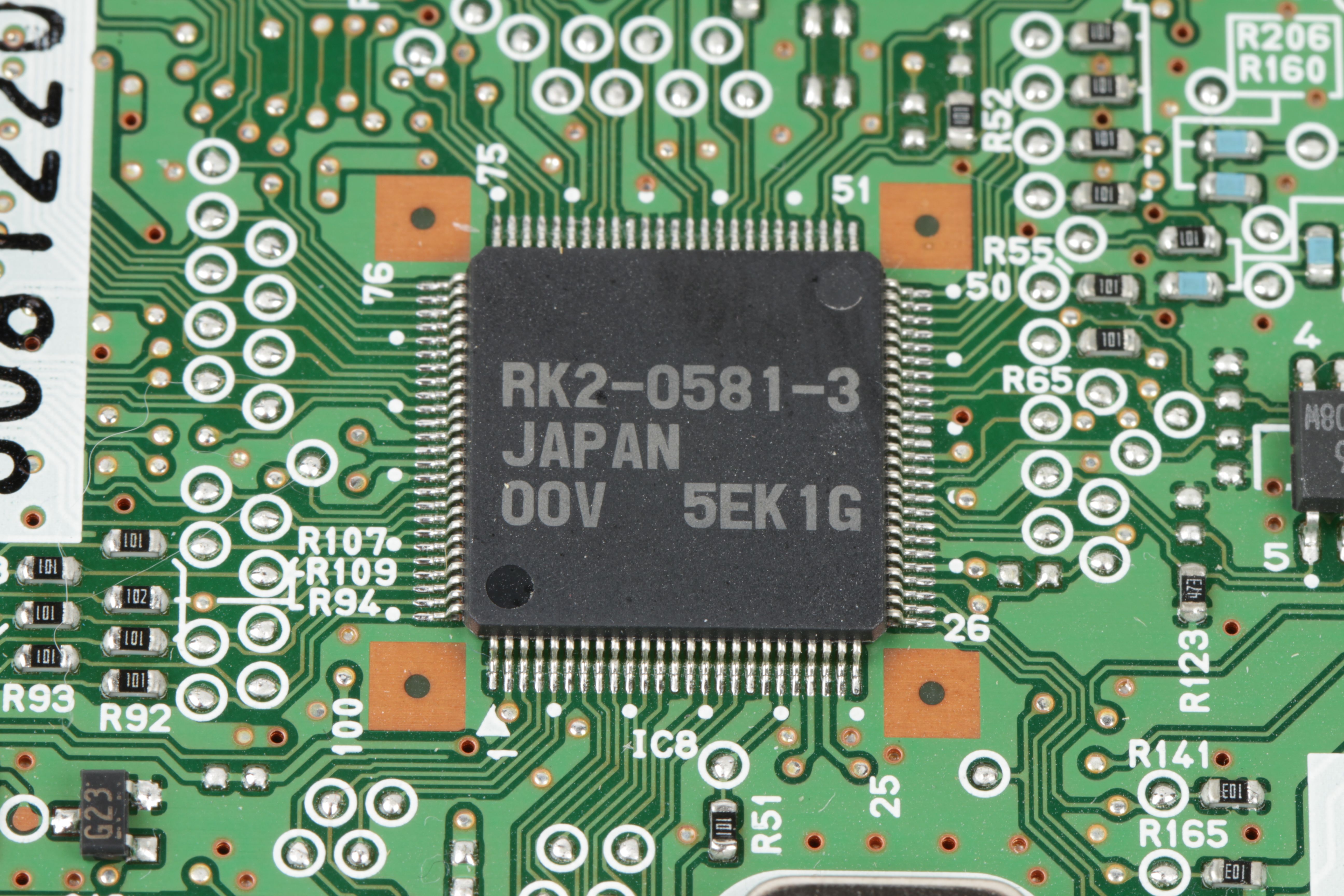
Here’s another chip that’s somewhat ambiguous. Pin 1 is clearly marked with an arrow on the circuit board. If the chip were loose it would be a little less clear because not only is there a dot by pin 1, but there is also apparently a dot by the opposite corner. It may be just a coincidental mold mark, but it’s still potentially confusing.
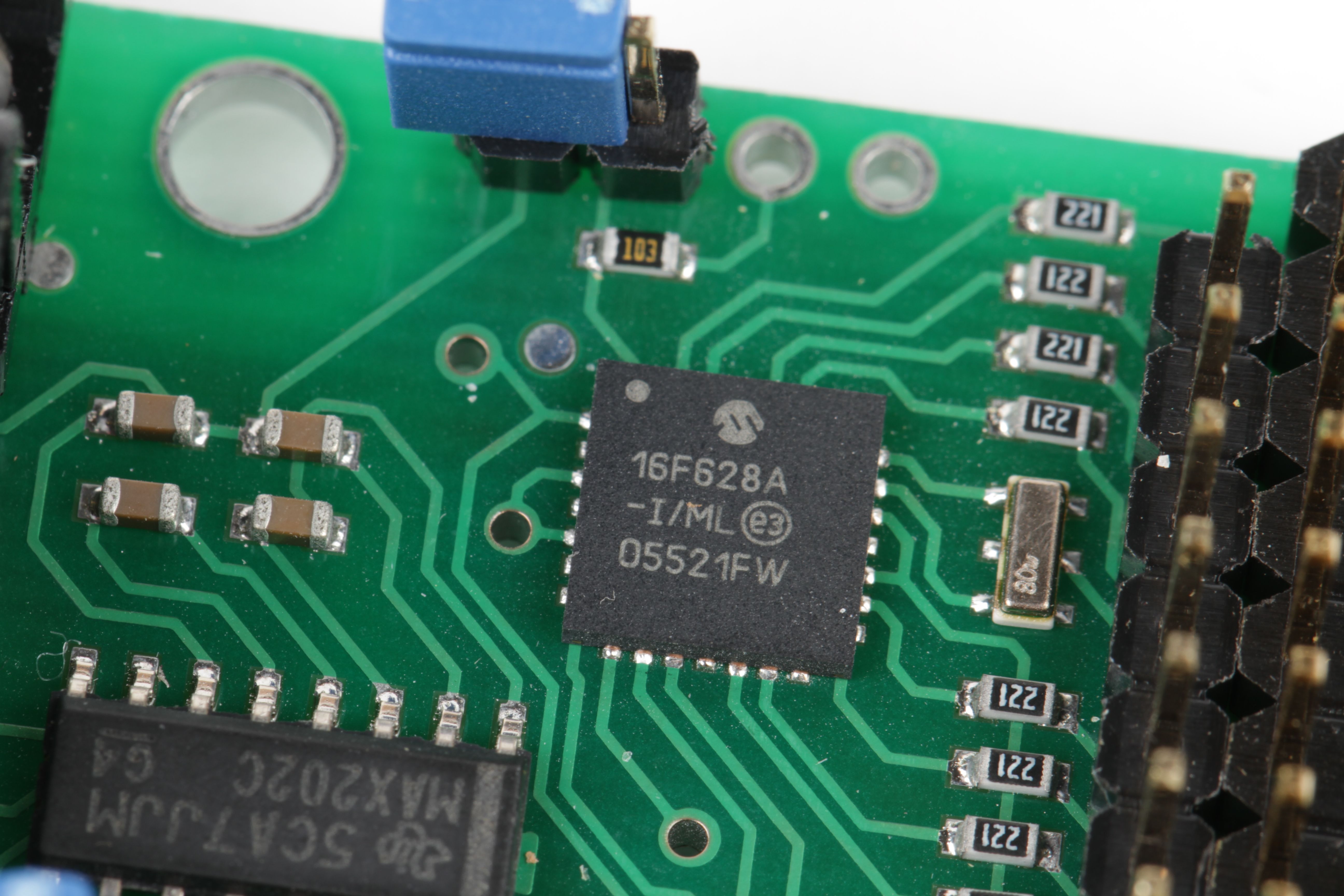
And here, a simple dot to indicate the orientation.
This is far from an exhaustive list, but is meant to show off some of the common ways that chip orientation is differentiated. If you have corrections or links to other interesting chips, we’d welcome them in the comments.

A handy article!
This is conjecture, but the missing pin on the seven pin DIP could be to create a gap between the high voltage AC pins rather than for orientation. We have to be a bit careful to space tracks out here in the UK with our 230V mains.
Beautiful photos make this article interesting even for those who already new all this!
I ‘d like to throw in a CLCC44 (Ceramic Leadless Chip Carrier) package, sadly I have no chance to take a picture right now. Pin 1 is the center of the pins on one side, the count goes around counterclockwise as usual. The corners of the package are notched except for one, which is between pins 6 and 7.
It’s a prototype with a detachable lid and the frame where the lid sits on has a tiny triangle also pointing to pin 1.
Great article. Here is a suggestion for your next article: could you please add the polarity for capacitors and diodes? I hate how smt tantalum capacitors are opposite of the diode markings.
Yes, that’s a good suggestion. There’s unfortunately *way* too little standardization about this.
It’s a big topic, though, so it should certainly be separated into a new article.
Windell H. Oskay
drwho(at)evilmadscientist.com
http://www.evilmadscientist.com/
Great article, thanks for photographing, writing and sharing :)
what is the part number of the SSR? Sounds like an interesting part.
This one is a PR39MF22NSZF. There are many similar parts though. They’re useful and inexpensive parts.
Windell H. Oskay
drwho(at)evilmadscientist.com
http://www.evilmadscientist.com/
Pin 1 is not always on a corner as one might expect.
For example on a PLCC the first pin is always at the middle of the upper side.
Nice 2114 SRAM chips.
The ceramic/metal package that the 2114s were in was exploited to make some early, experimental camera chips. To do this, a DRAM in such a package had the metal top ripped off to expose the Silicon chip. Then, data was written to the chip (either all 1s or 0s, depending upon the particular chip), and it was progressively read out. As the light caused the charge to bleed off, the data would gradually decay, and this could be used to determine how much light was falling on each memory cell. By the appropriate manipulation of the data read versus the decay rate, an image could be created.
Dave
Great article.
Although i dont think the finding pin 1 for the 17 segment display is correct. Looking at the 17 segment you have in your store, pin 1 is indicated in the opposite corner, not under the DP. With the 17 segment displays i have used, pin 1 has been in the top left corner (when looking from above).
Oops-yes-thank you!-edited-fixed.
Windell H. Oskay
drwho(at)evilmadscientist.com
http://www.evilmadscientist.com/
Isn’t that a decimal point on that alphanumeric display?
You hardly ever see those away from the lower right corner of the character. (Built too many digital displays ….)
If you know what the chip is supposed to be, quite often it might be useful to start tracing the ground plane.
At least, I seem to run into chips where the markings are between "nearly illegible" and "completely obliterated or obscured."
But for simpler circuits, you can generally figure out which pins are connected to ground. This can apply to many uses of the various three-pin transistors as well – where the key information is buried in thermal compound and mounted in a heat sink.
I would assume that the seven legged beast has seven legs NOT to make it imposible to put it in place "backwards" but to provide the needed spacing on the AC side of things. (as far as I remember
6 mm are needed / mandated for 230 VAC).
"THX 1138D
1337 OHAI"
LoL!
Gosh. You guys better have your own college, cause that’s where I wanna go when I grow up.
Generally when trying to discern between polarity markings and other molded indentations the deepest mark is the polarity marker.
I had been trying to find info on “finding 1st pin” on SOIC with “bar” mark for some time and wondered that that’s a quite rare information. Even wikipedia knows nothing about it). So happily I’ve found your site =) Thanks a lot!