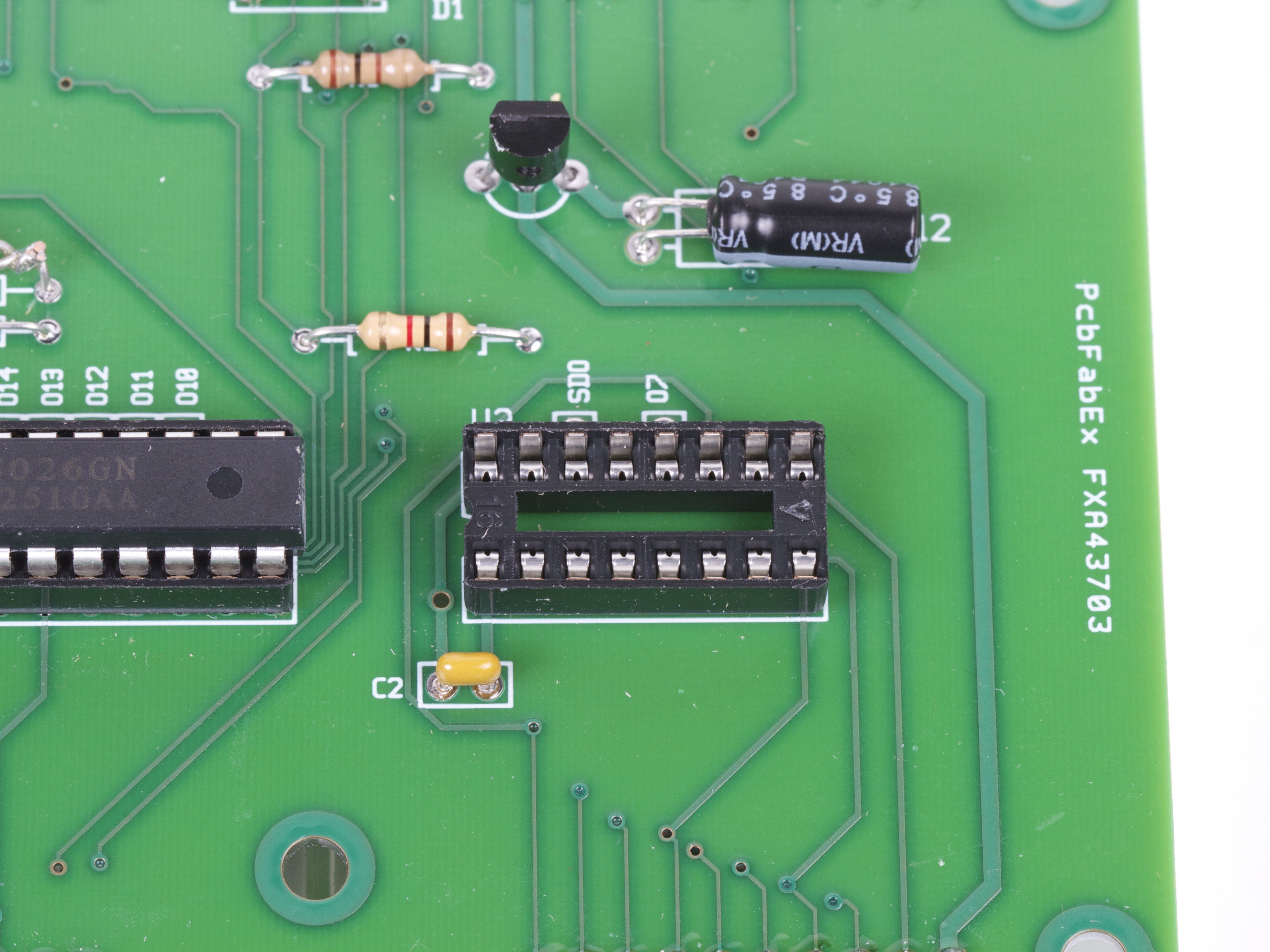
So, you’re almost done building the new circuit board when suddenly…
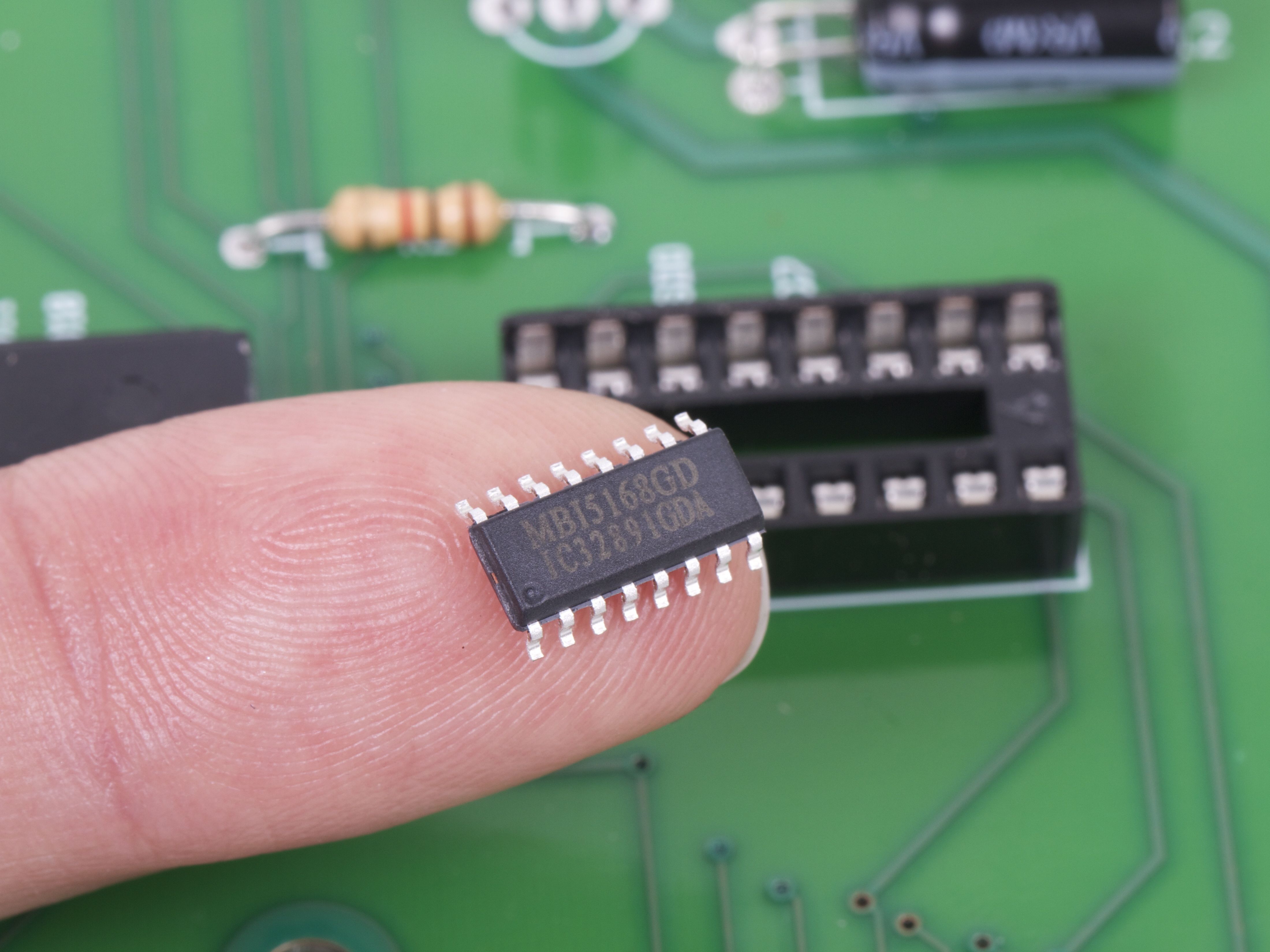
Doh! We’ve got the right chip handy, but only in the wrong package!
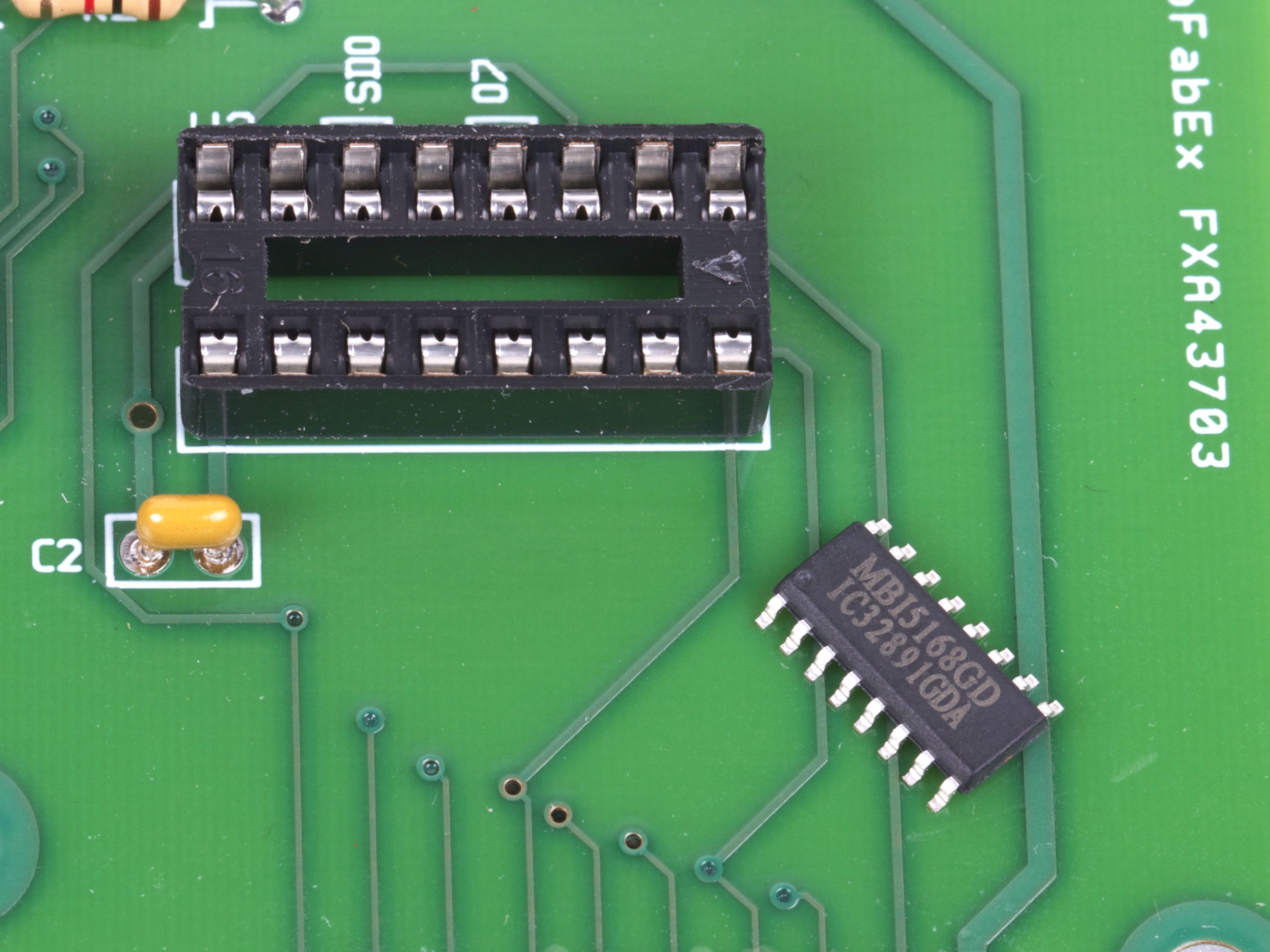
No siree, that chip will not fit in our socket. :(
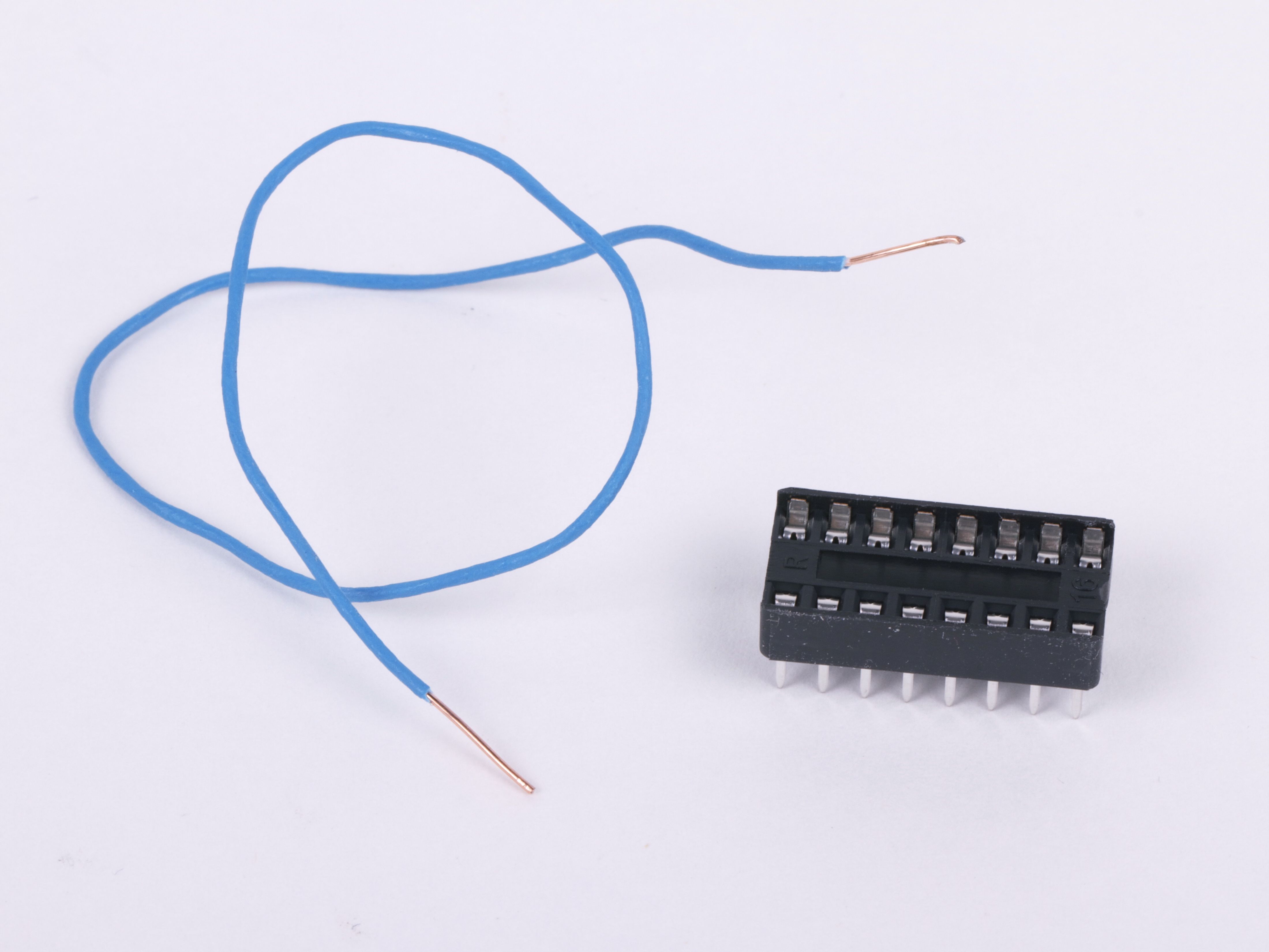
Fortunately, we’ve got tools: some thin copper wire, a spare DIP socket, and a few minutes of time. So, even without a readymade SOIC-to-DIP adapter, we’re still good to go.
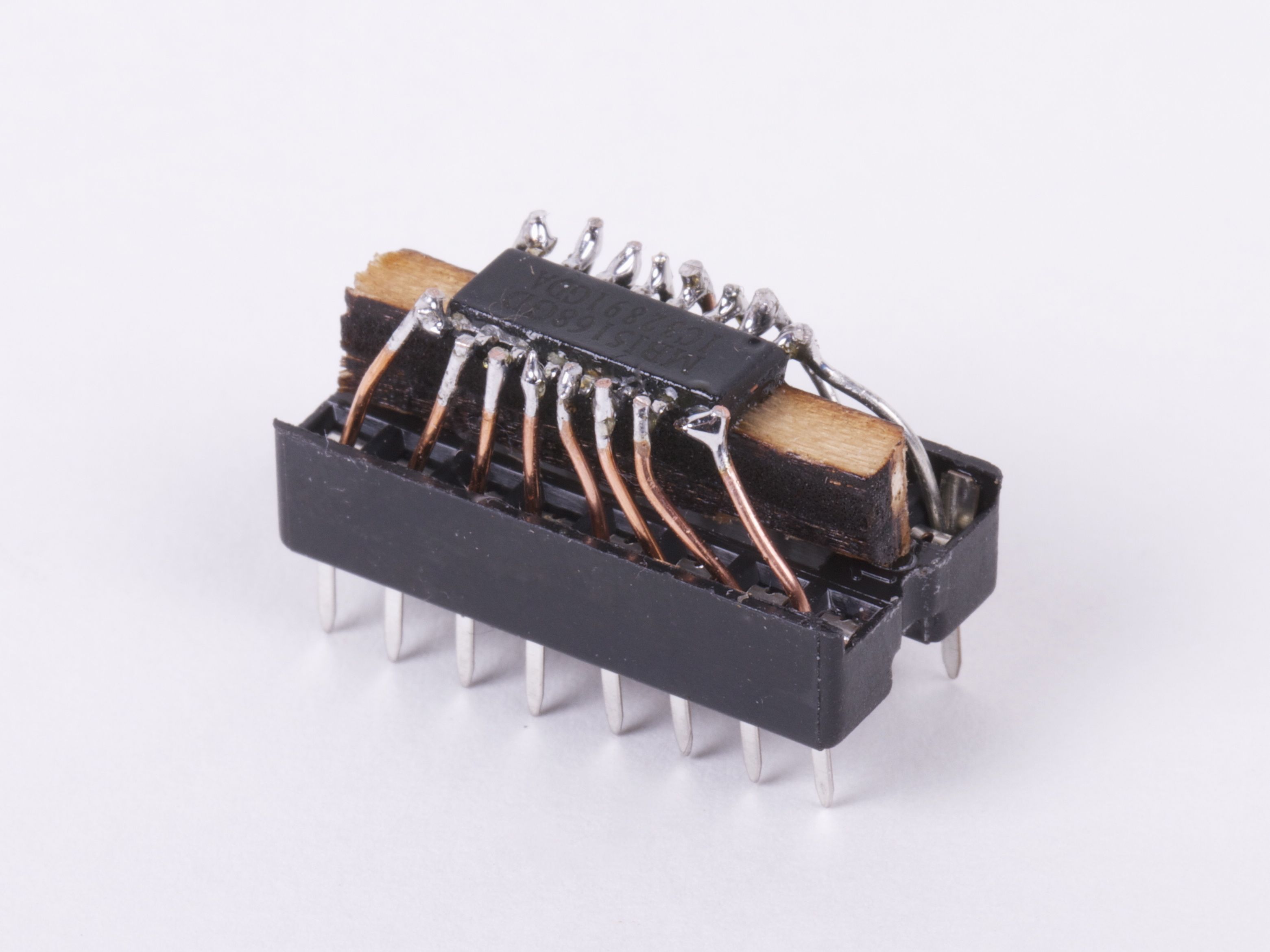
It’s helpful to raise the little chip up a bit with a wood or plastic shim, and then to fix it in place with hot or super glue. Strip the insulation off of the wire, and cut into small sections. Starting at the center of the chip, insert one end of each little wire into the socket and solder the other end to the matching pin of the IC. Trim the leads just above the chip.
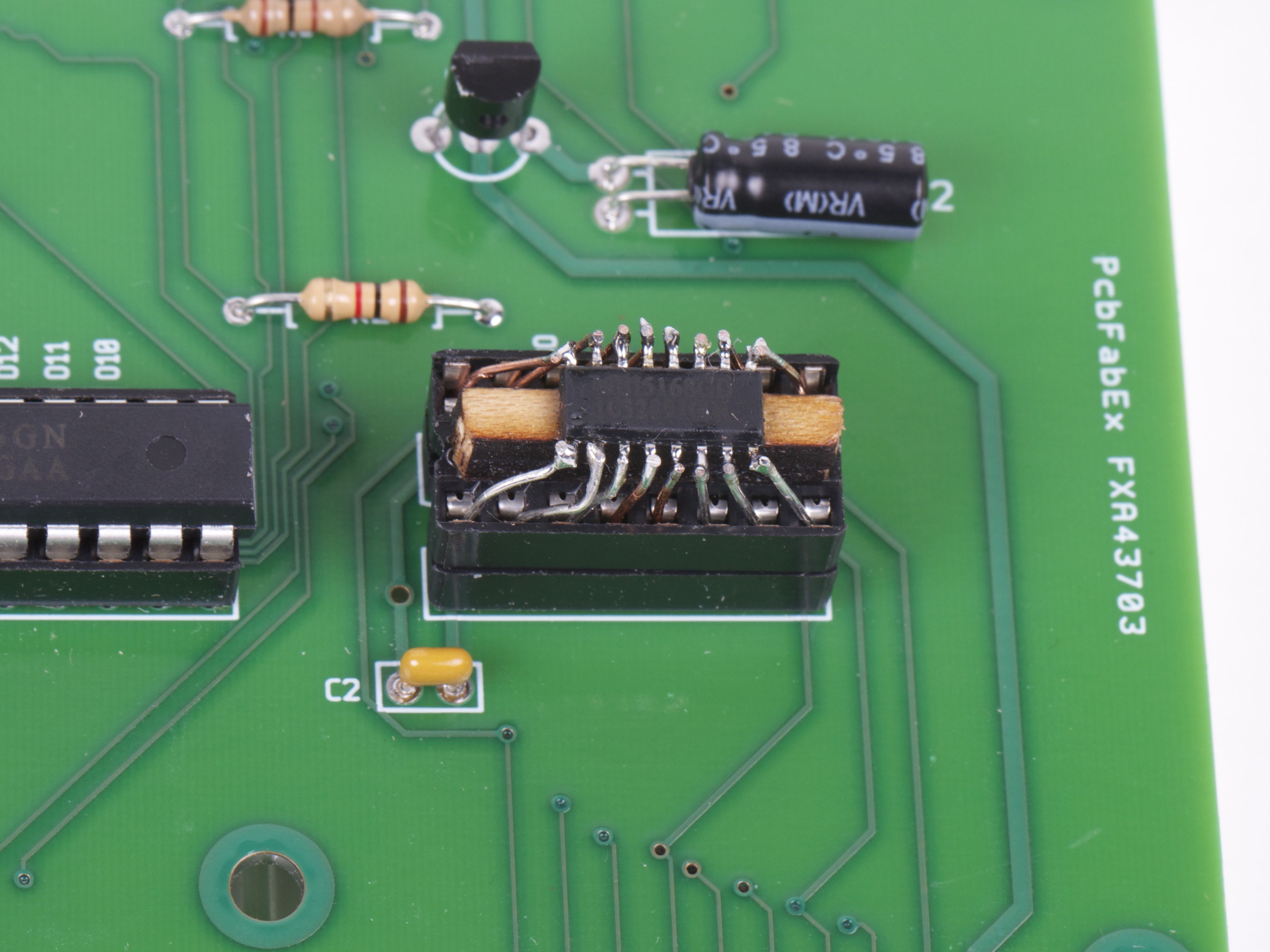
And (poof!) it fits in the circuit board after all.
Beautiful? Heck no. (More like
slimy but satisfying.) But finding a way to get your circuit board to light up
without a few more days for the “right” chip to show up can be a wonderful thing indeed.


I had to do the same thing, with a tiny transformer (!)
http://farm7.static.flickr.com/6049/6299973130_d770467d20_z.jpg
http://farm7.static.flickr.com/6034/6300647773_4f212063b7_z.jpg
http://farm7.static.flickr.com/6104/6300648163_3d9e412599_z.jpg
some hot melt as a ‘bed’, then some wire wrap (like you used) on a socket. my approach was to make the chip into a carrier and then that whole thing plugs into the socket on the board, below.
solder the wires into the socket holes, first. then bend and cut them to exact position. the leads hold themselves up and you can tack solder this way.
would not want to do this very often, lol.
These are great! Hot melt glue and tiny, tiny solder joints!
Windell H. Oskay
drwho(at)evilmadscientist.com
http://www.evilmadscientist.com/
I think I wouldn’t start by cutting the wire into short segments. I would leave it long so I have something to hang onto, then after soldering it to each leg clip it off.
Still, this is an amazing idea!
You did that in 5 minutes?! I wouldn’t call myself a slouch but it would be a draw between my finishing that and getting the differently packaged version in the mail ;) But then I waste a lot of time in the motivational stages before soldering actual begins…
May not be beautiful but has a sort of cannibalistic-spider-chip charm about it. Wouldn’t make too many in case they start trying to take over the world, however.
Kudos for a nifty kludge, which ranks only slightly behind an elegant hack.
I did get confused by one thing though: the angle and lighting in photos 5 and 6 just happen to make the chip markings a little hard to see. For a couple of minutes I thought you’d flipped the chip over (dead bug style) for better access to the pins. That would have reversed the chip’s pinout though, and that wouldn’t work in the circuit. If I’m the only doofus who tripped over that, may you continue to be blessed.
As a side note, I tend to use 30 gauge wire or smaller for similar jobs. For distances less than an inch or so, phone wire (24 gauge) is pretty stiff.
My rule of thumb is "the span should be at least 50 times the diameter of the wire." That’s roughly where beam theory says wire will stop acting like a bar that has to be bent (plastic deformation dominates) and will start flexing (elastic deformation dominates).
Great hack, but when it comes to dealing with semiconductors, I’d say "Poof" is probably not the best choice of words.
;-)
Nobody seems to be asking what to me is the obvious question here…. what is this new project?
Clearly it involves some LEDs because an MBI5168 in any other package still smells like an LED driver. However, it seems unlikely that it’s a mass LED project like the peg-boards etc because there’s no apparent bank of these drivers and you probably wouldn’t bother doing the hack if you needed to do dozens of them…. humm.
Moving on, besides what appears to be a power supply Vreg & capacitor there is a resistor or two and a further capacitor which tell us (me at least) nothing. We then have a fragment of a part number "251GAA" on a DIP package. Now we know how mad scientists like thier microcontrollers and there happens to be a part that comes pretty close to this : TSC87251 (G1A is the closest I find to GAA but I’m sure that’s insignificant).
Now the ‘251 is an 8-bit microcontroller that comes in a 40-pin DIP package (check!). But why use this rather than the familiar ATtiny/ATmega controllers that we are so familiar with? Well, the main difference apperas to be the ability to use up to 256K in external memory, accessable thought four 8-bit interface busses which take most of the pins on the chip. An interesting point is that pins 23-27, are alternatively designated A10-A15 respecively, and would correspond to the "D10-D14" PCB marks we can see.
So, overall, I think we can conclude that this is a microcontroller project using a TSC87251 or closely related processor. It uses probably only one 8-chanel LED display, such as a 7-segment, and it likely requires more data that can comfortably fit in the 32K of an ATmega 328.
Anyone else with a better guess?
All will be revealed soon. :)
Windell H. Oskay
drwho(at)evilmadscientist.com
http://www.evilmadscientist.com/
Of course, I could be totally wrong and the "026" could be another LED driver – MBI5026 or similar. But why two different types of LED drivers?
Who knows? I shall wait with interest!
This method works very well, I have used it a few times when I only had the SMD version of a TTL oder CMOS chip I wanted to use (or just wanted to get rid of an SMD IC that I would probably never use on an SMD board). I use 0.2mm enameled copper wire and solder both ends (the IC sockets can be soldered to very easily, without the socket melting), then put a strip of insulating tape between the socket and the SMD IC. Here’s an example: http://elektronik-kompendium.de/public/arnerossius/schaltungen/mitics/countdown-oben.jpg
This is a valuable technique when you are in a pinch, especially since it can work for "any size" chip.
But it’s also worth noting that SOIC/SSOP to DIP16 adapters are around $1 on Sparkfun (with qty10 being super cheap on ebay… with DIP8 ones costing $3 for qty 10). That’s cheap enough to order a few for the toolbox. Well, it’s worth it for me… what you soldered here in "5 minutes" would easily have taken me 20, lol.
Or… you could sand down an unneeded plastic-pack DIP chip until you’re at the pin framework level, dremel out the actual center-placed die, and solder the legs of the wrong-package chip to the exposed pin leads.
Lot cleaner looking & stronger.
If you can do that lot in 5 minutes, you’re a better man than I!
Good plan thou’.
This is just the quick kludge, and it only had to last two days until the correct chip package arrived. No need for elegance! :)
Windell H. Oskay
drwho(at)evilmadscientist.com
http://www.evilmadscientist.com/
Also, this way is a wee bit more Mad, if not necessarily Evil.
I think I am, therefore I am… I think
great, I gonna try it, thanks.
Probably worth mentioning that sometimes the SOIC pinout is subtly different to the DIP so its worth checking!
Ian