


Several years ago, we came across this interesting artifactat one of our local electronics surplus shops, and couldn’t really make heads or tails of it. But after the passage of the aforementioned several years– along with several dozen interesting suggestions from our readers –we haven’t been able to get much closer to an answer.
But then, at this month’s Electronics Flea Market, we came across what appears to bea related chunk of hardware:
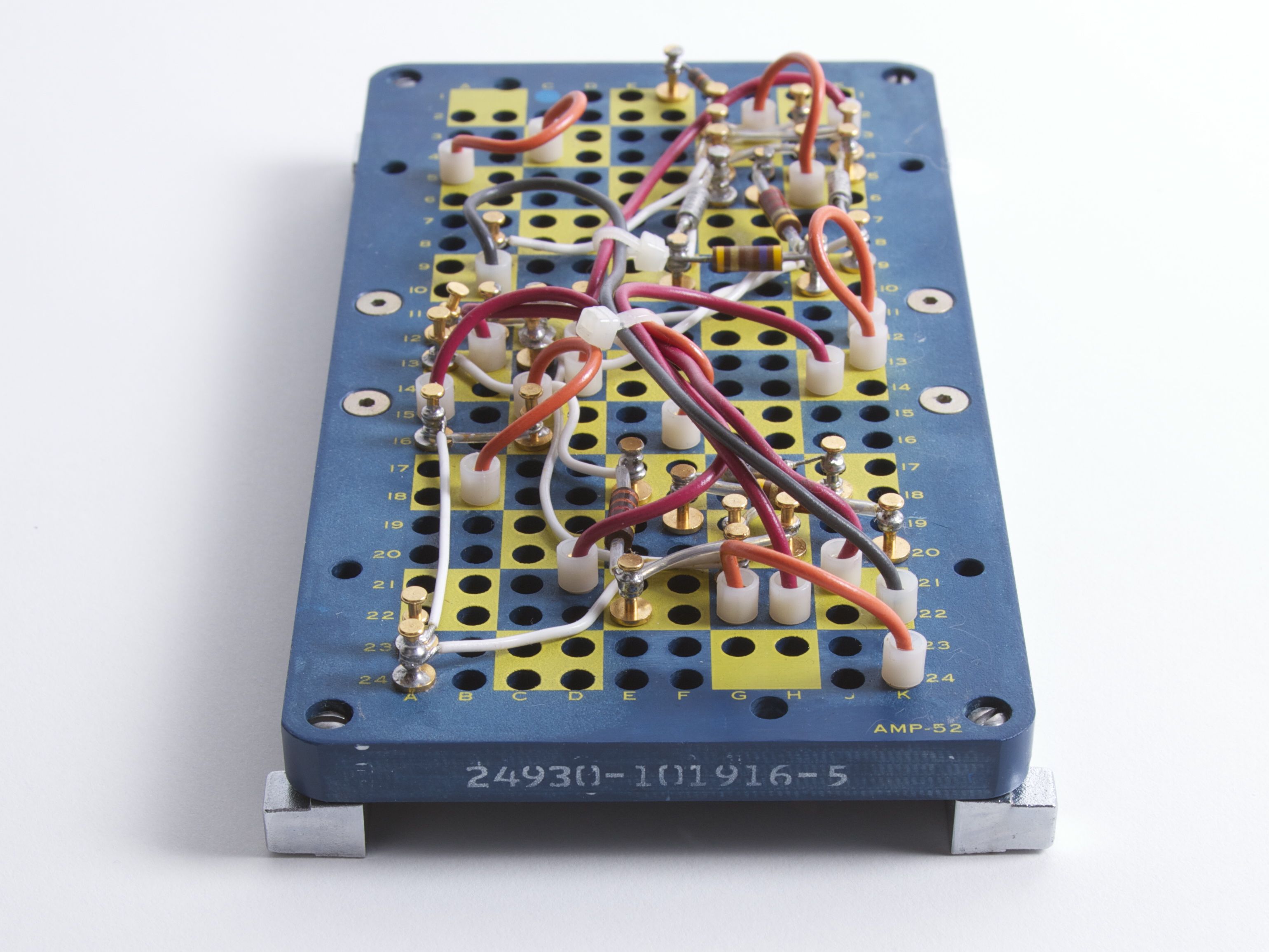
While we do not have the original “artifact,” the thickness and hole size of this new board are reasonably consistent with that of the other board. Certainly, the layout pattern is the same, suggesting that they serve the same purpose, if maybe not the same brand or manufacturer.
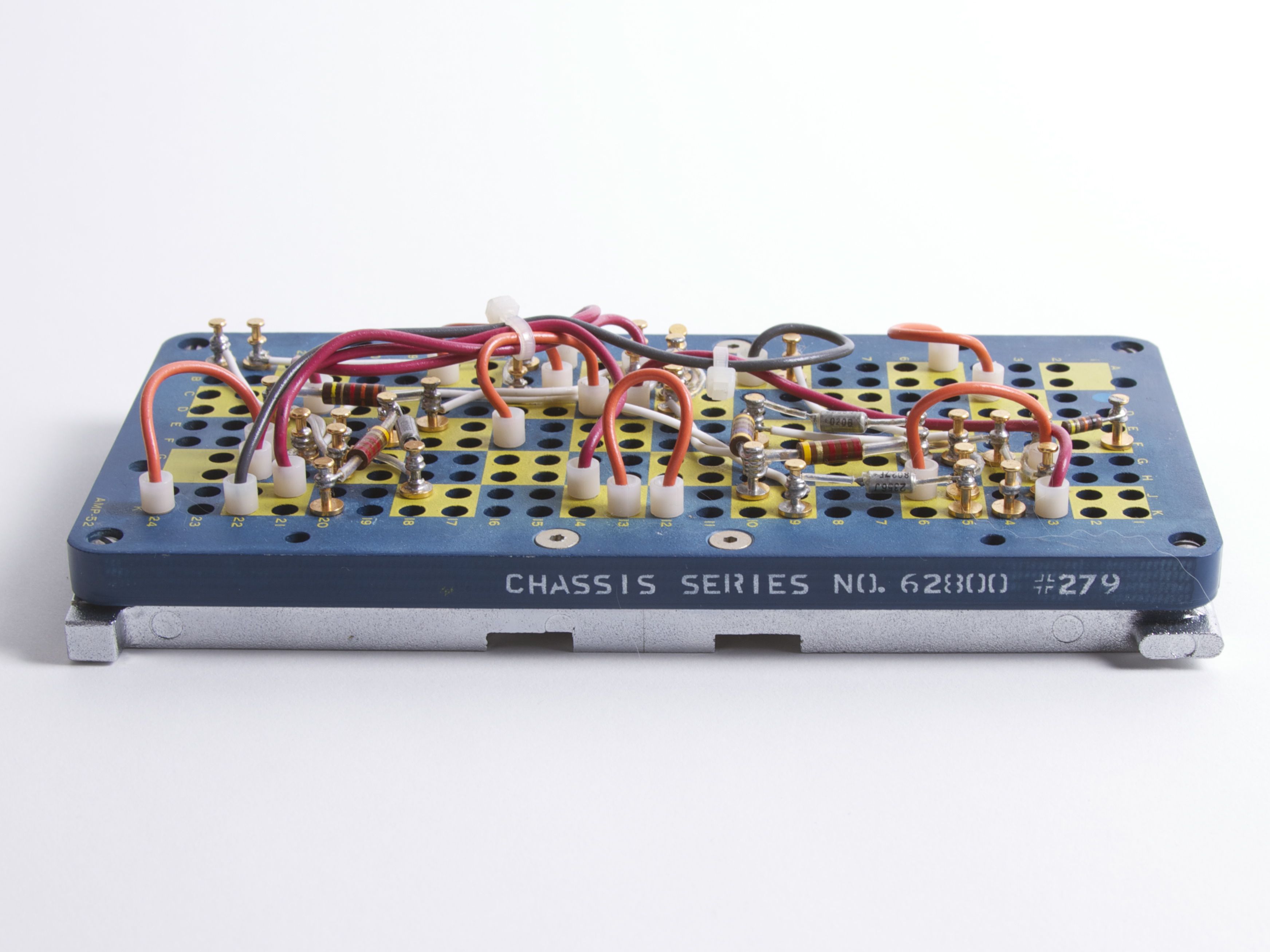
The visible markings on the different sides of the board are as follows: Chassis series No 62800 #279, 24930-101916-5, AMP-53, AMP 397503-4 8128. Amp is the manufacturer (they still exist, as a brand of TE Connectivity), and 8128 (week 28 of 1981) appears to be the date code.
The elements installed on the board– clearly some kind of electronic patchboard –come in a few different varieties. First, there are binding posts, anchored semipermanently into certain locations, with electronic components such as resistors, capacitors, and permanent wiring, soldered between them. There are also movable “patch” cables (the ones with the plastic rings on the ends) that can be moved from point to point.
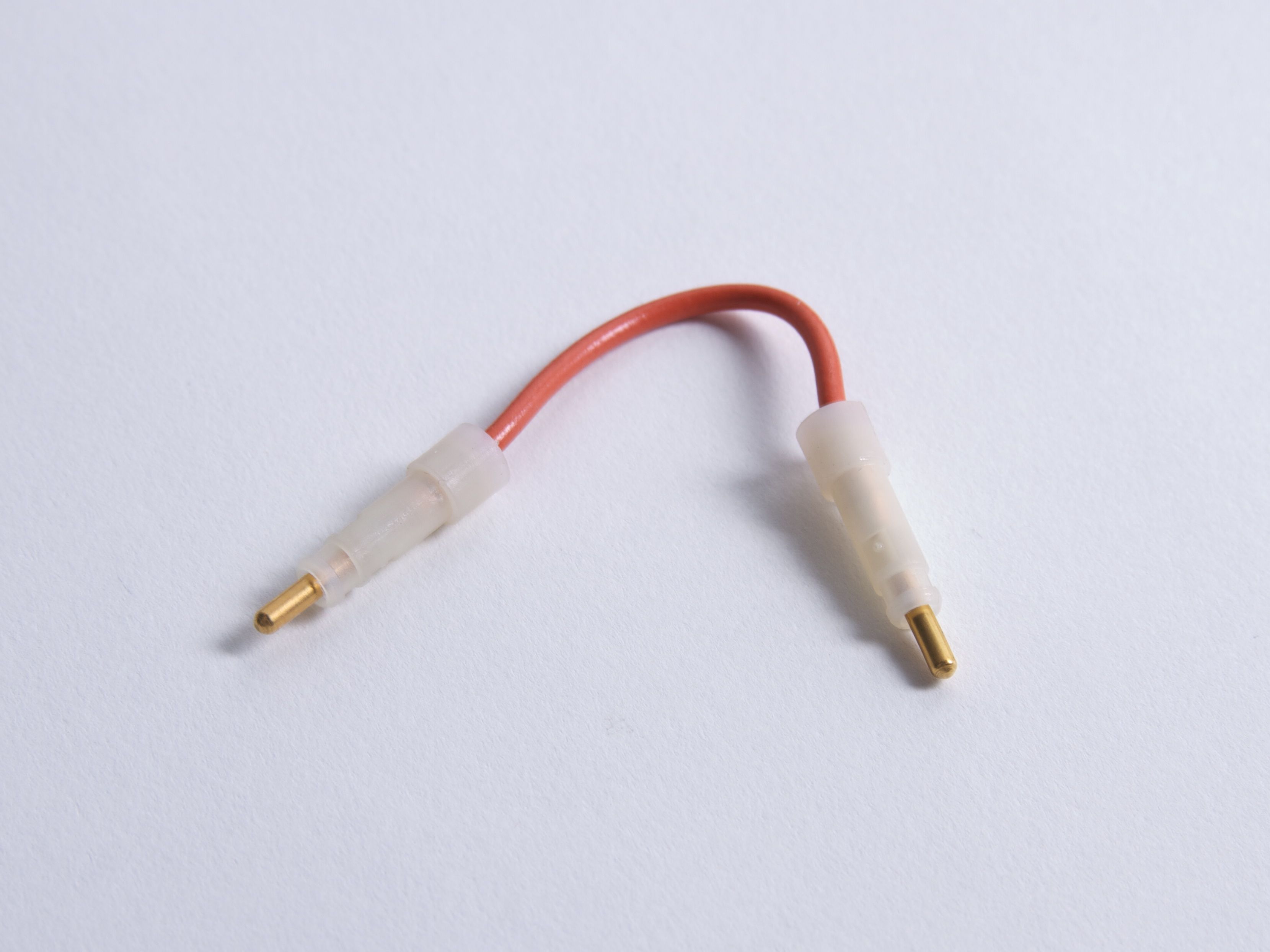 Here’s what one of the movable patch cables looks like: just a single insulated conductor, that snaps into place.
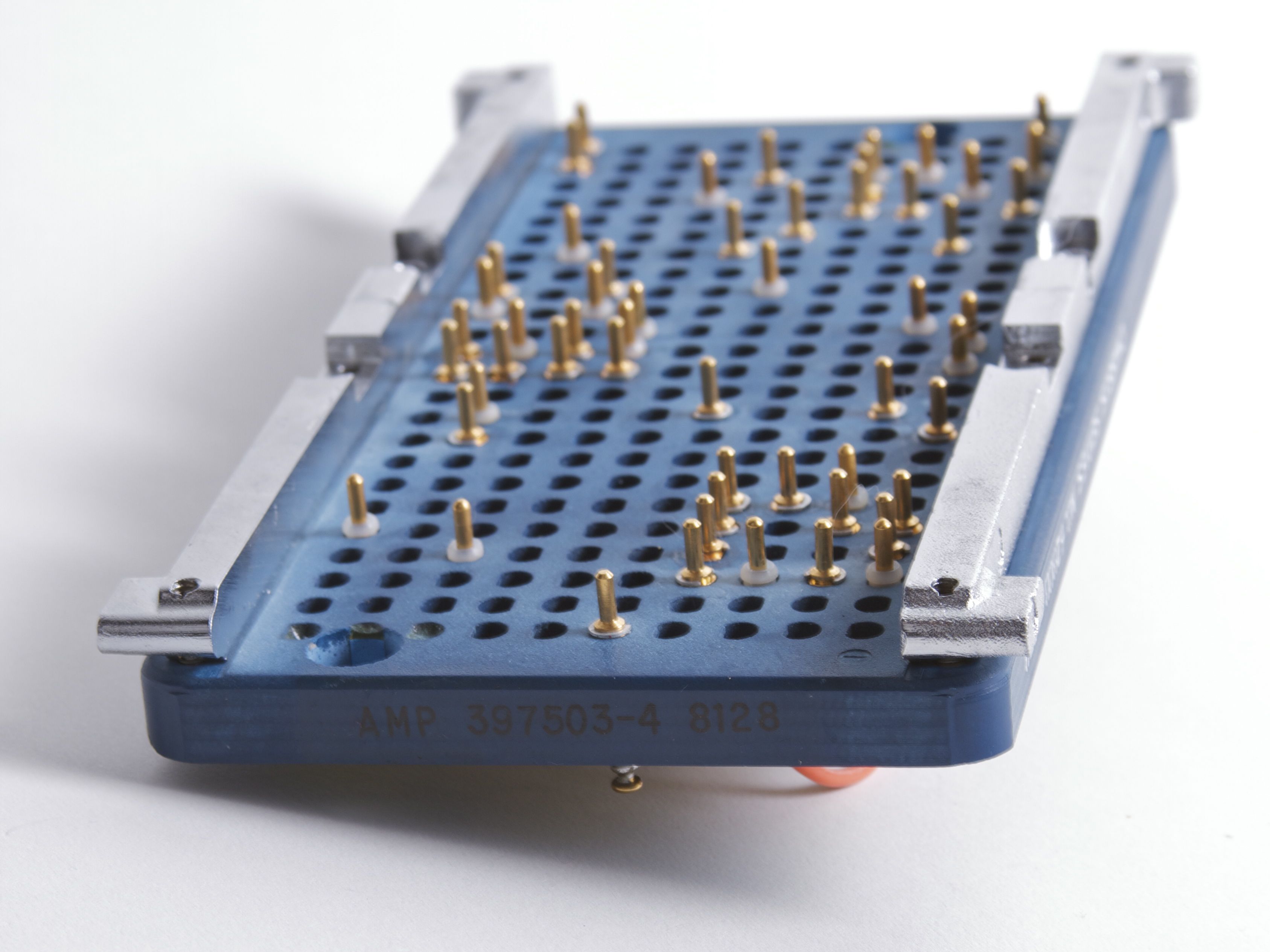
Every binding post and cable inserted from the top sticks all the way down through the bottom, with a gold plug showing through on the other side. The blue patchboard itself is just a passive chunk of plastic– there’s no internal wiring. So it’s clear that this whole assembly itself actually plugs into something else: some kind of backplane that connects the electronics together in a prescribed manner, and can be reconfigured with the movable patch cables.
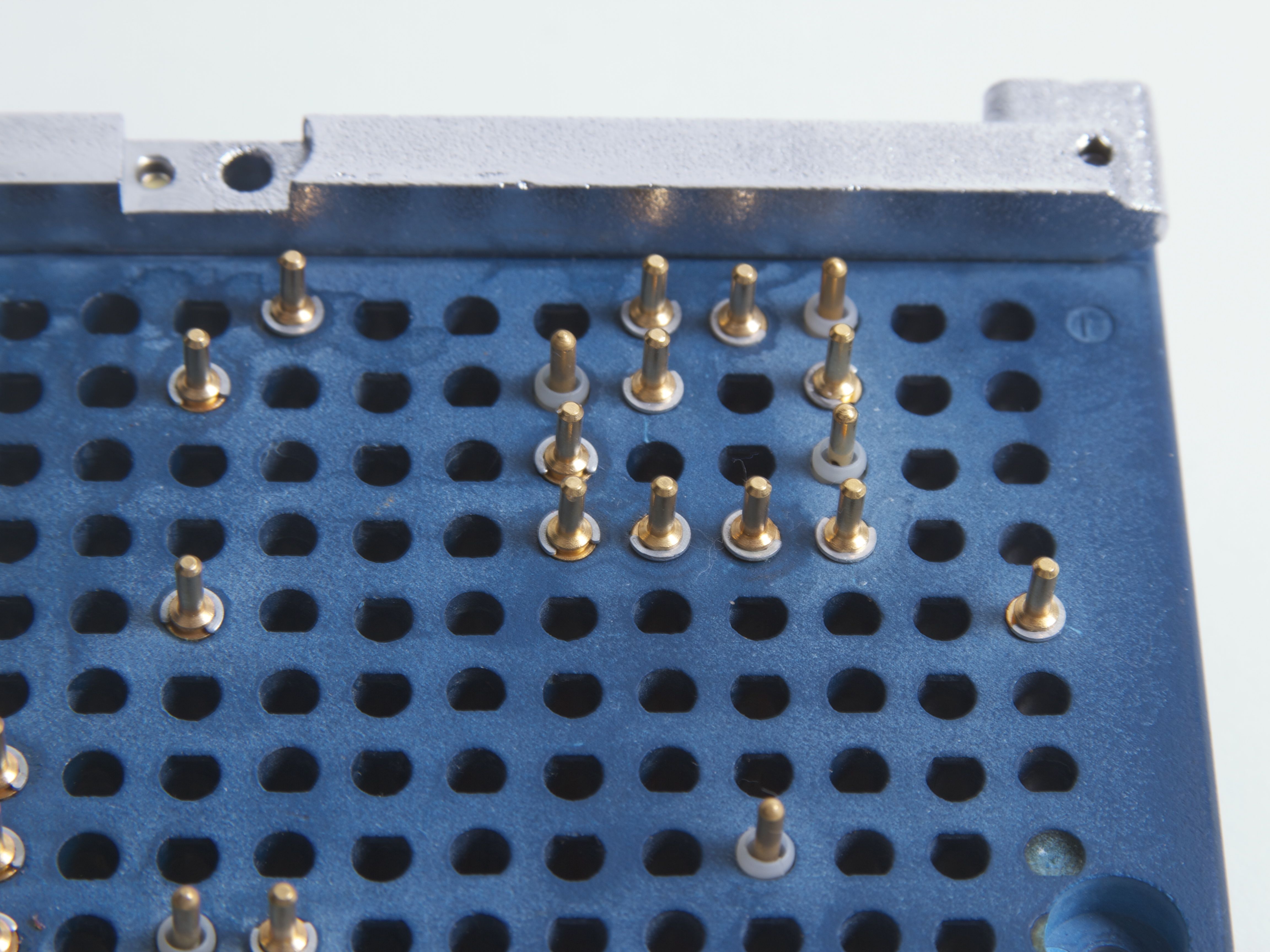
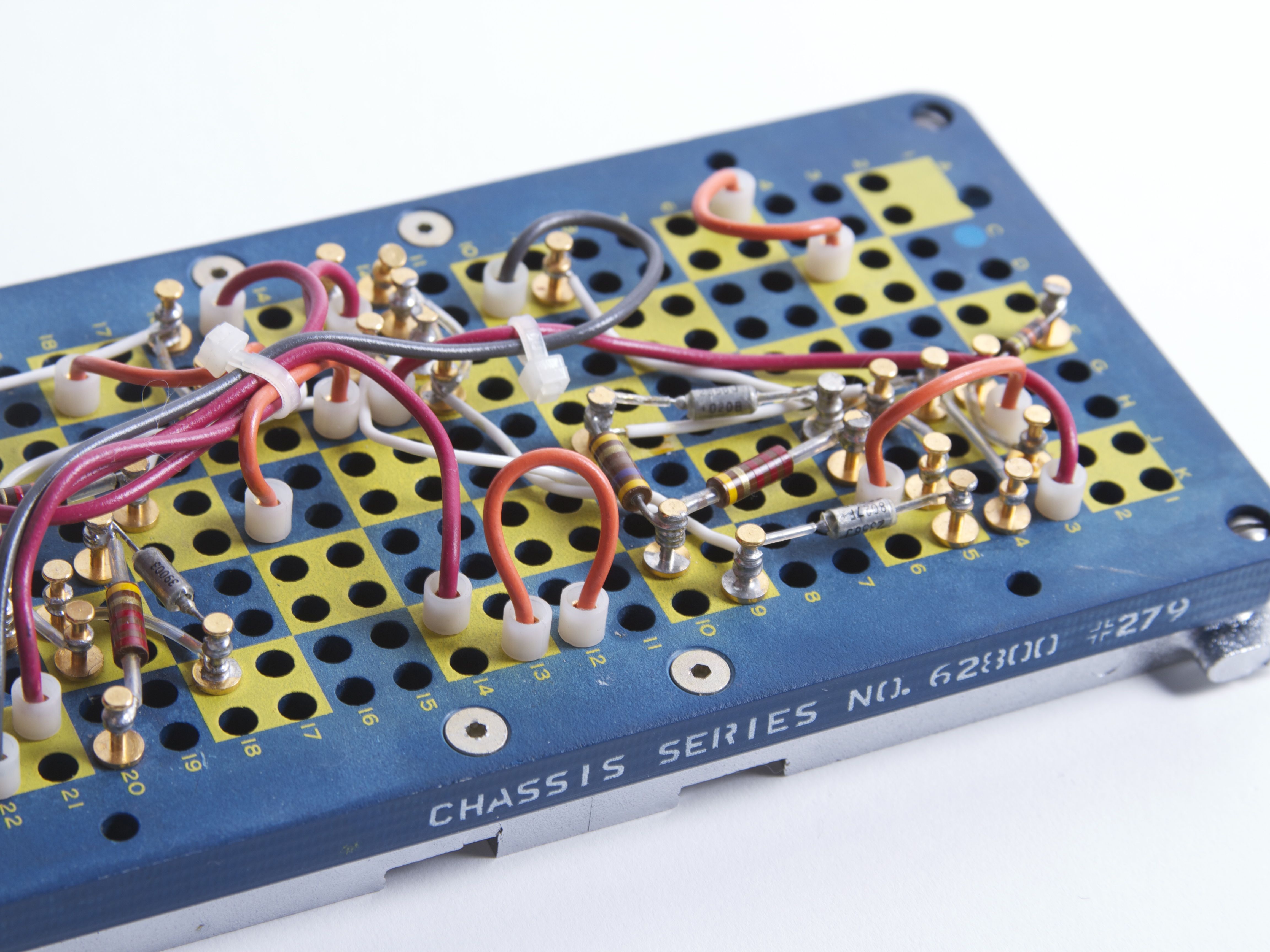
If you look a little closer at the back, you might notice that the holes appear to be D-shaped. It turns out that the hole is circular until the very bottom, where there’s just that little lip on one side. This lip provides a little snap-action detent when inserting or removing a patch cable, and probably also prevents the semipermanent components from rotating. You might also notice why those binding posts are “semipermanent”: each one is held in place with a little snap ring.
In a sense what we’ve found looks like the military-grade version of the common electronic breadboard. But some of the big questions still remain. What kind of instrument or machine did this come out of? What did this board actually plug into? Was its “backplane” the interface to a complex system, or just a simple block that connected together the four pins in each checker-square together? And, why so rugged?
Armed with the manufacturer name and the new certainty that this is some kind of patch panel, we did some more searching and turned up what appears to be an actual usage example of one of these panels, at the scale of our original artifact:
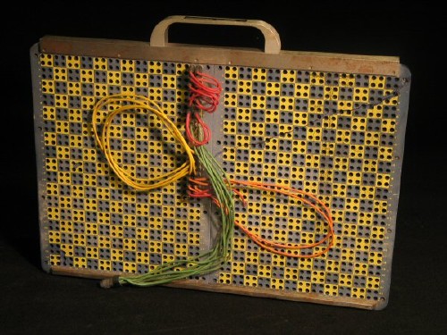
This patchboard cartridge— this one consisting of two of these AMP panels together in a frame with a handle –is one of ten created for a set of art and engineering performancesin the mid 1960’s. The engineers devised a way to quickly reconfigure stage wiring between different acts going on stage, all of whom needed different wiring.
For each act, they configured the stage wiring appropriately the patchboard: Mike 1 goes to Effects Processor 3 to Amp 2 and so forth. Once the wiring for a given act was complete, all that they had to do was remove the front panel– as a cartridge — and set it aside for later use. Because the custom wiring is attached to the removable cartridge, it’s easy to quickly switch between customized setups. And with the rugged design, it will survive repeated insertion and removal without dislodging the patch wires or any semipermanent electronics installed on board.
(Photo: Éric Legendre. From The Daniel Langlois Foundation for Art, Science, and Technology, 9 Evenings: Theatre and Engineering fonds.
http://www.fondation-langlois.org/html/e/page.php?NumPage=294)
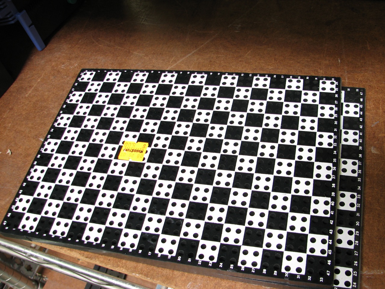
Now, to revisit our original mystery object.
This one was made of modern injection molded plastic. These things often show their age, and those didn’t appear to date back even as far back as 1981. The design is in the style of those older patch panels, and it is very likely that it was used in the same way– as an interchangeable faceplate for a patch bay of some sort.
There are some differences, however. For one thing, the holes sizes and spacing don’t appear to be an exact match with the Amp panels. Perhaps more importantly, the holes are circular all the way through, without any D-shaped retaining lip. The retaining lips are necessary in the Amp boards, because there is significant insertion force when the patchboard cartridge was plugged in and all those pins (including the movable patch cables) need to make contact with the corresponding pins in the backplane– and not pop out in the process. But these don’t have that feature– so it’s reasonable to suppose that the insertion force from swapping cartridges was much lower.
So what does it all add up to? Here is our conclusion: This a fiber optic patch panel, part of an interchangeable faceplate system, that allows the operator to quickly switch between different fiber optic “wiring” configurations. The faceplate brings the fibers up to the backplane, which they butt up against, rather than insert into. An old solution to the modern version of an old problem.
So once again, we’ll open it up for questions as well: Have you ever come across any of these? Got one to show us, or a different conclusion? We’d love to hear about it in the comments.
Broken link "this interesting artifact" – has a stray double quote at the end.
Fixed, thanks!
Windell H. Oskay
drwho(at)evilmadscientist.com
http://www.evilmadscientist.com/
http://bluebook.state.or.us/images/facts/scenic/work/work14.jpg
it was probably a telegraph / telephone operator switch
These are programming patch panels from unit record equipment. These were the hardware predecessors to an early programming language called Report Program Generator (RPG). One wrote programs by filling in pre-printed sheets of paper with codes which selected the fields to be printed, sort order, and filtering, then a technician would take the paper and wire up the patch board with the program, which would then be plugged into the “computer” (really more of a card sorter / printer driver). They continued to be in use well into the 80s, then disappeared when cheap replacements in the form of PCs became available.
It seems likely that the Amp board that we found is of the same type used in those machines. However, the original "artifact" does not appear to be the same thing.
Windell H. Oskay
drwho(at)evilmadscientist.com
http://www.evilmadscientist.com/
It’s been a long time, but the Amp boards look more typical of some of the later IBM accounting machines, whereas the checkerboard ones look reminiscent of older (and larger) Honeywell (or whatever the predecessor company was) machines. Don’t get confused by the manufacturing dates, the patch boards were produced for years after the machines themselves were obsolete. A typical IT shop back then had racks of pre-wired boards for performing various canned functions. The patch cables are often missing when they show up as surplus, as the gold plated tips made them worth recycling.
The boards in IBM’s machines were usually marked on the front side with the plug area names (column numbers and the like). They came in different sizes for different machines – accounting machines had large boards, but reproducing punches had small ones. The plugs were generally round-tipped and not locking, because they had to be easy to remove and rearrange. There were ones for connecting adjacent holes where the tips were permanently connected as a block, and splitters of various kinds (when you needed to send the same signal to several places).
(Why, yes, I am a computing dinosaur.)
You are right, I remember these plugboards that worked in IBM collators and sorters I remember were in the back of the datacenter in 1974. I had friends that had programmed them.
Some people I worked with also used similar boards with ‘accounting machines’ that had used them. and had printers associated with them. Unit record machines were very powerful, and state of the art ‘back in the day’.
The folks I worked with said they would generate programs and would purchase additional boards, so the number of boards would add up as the number of programs companies used on them increased.
In the ’80s I found lots of them in surplus stores.
We use these to pre wire all fiber connections back to the optical network(sonnet). Then as customer orders come in we patch to the coordinated positions on the front of the panel(called cross connect). When the word doc is sent to the central office, a Co tech or radio video tech will then place the patch cord or loop test from the front position, completing the circuit.
It definitely reminds me of the patch bay on this old Synthi:
http://www.flickr.com/photos/sentman/5662093421/
If you do a google image search on "analog computer" you can see that a lot of them have these kinds of removable plugboards.
Essentially a analog computer is a bunch of operational-amplifier circuits that can wired into different configurations (adder, difference amplifier, integrator, differentiator, …). Also they provide referencce voltages, input/output amplifiers/converters, maybe a built in oscilloscope and voltmeter.
They can be wired up to solve (differential) equations, so that you can -for example- balance some unstable mechanical setup, play pong, move a gun so that it will hit a target taking wind and gravity into account and so on…
As these "programs" consisted of a *lot* of cables being plugged in, connecting the inputs/outputs of the single modules, they were made removable to be able to change them faster than un- and replugging all the time.
So, that’s my guess: Plug panel for an analog computer.
It looks like the backplane of the professional (not the kids-toy version) Denshi Blocks:
http://www.denshiblock.co.jp/
These used to be used on old test equipment where I work. Specifically, on an old In-Circuit Test (ICT) system made by HP, model number 3065. That board really is a large breadboard of sorts.
It is used on the bottom of board-specific test fixtures. The holes are loaded with pins, which are wired up to specific test probes on the fixture. The probes make contact with various points on the board under test, which is held down using either a clamp or vacuum pressure (depending on the board). The pins loaded into this board plug into an interface on the HP3065.
Inside the HP3065 are hundreds of parallel relays, multiplexers, buffers and measurement instruments. The ICT is capable of testing individual resistors, capacitors and inductors on the board, as well as digital components. Of course, it also checks for shorts and continuity.
So, if you are a large manufacturer you’d have dozens of different fixtures, one for each different board. Each fixture would plug into the HP3065, and software is loaded up to test that particular board. And on the bottom of each fixture is one of these boards.
>> "patchboard cartridge"
I think that this sort of "cartridge" must have been a pretty common concept in various early "computing" environments. I remember my dad bringing home a similar-but-different panel with jumper wires (plain panel, metal frame, ~3mm plugs on single-conductor cables that extended THROUGH the panel, handle at the top, etc.) for me to play with in the early to mid 1970s. He worked for an oil company; I don’t know whether the device came from the IT department or from the refinery/technical side of things, but I can picture either one.
Actually, it came from an HP-3060A and is called a mac panel. The panel held pins which contacted gold plate fingers on the fixture receiver. Wire wrap wires were used to connect between the patch panel and the test pin sockets on another panel above the patch panel. The fixtures are still available: http://www.stentech.com/054~Test_Fixtures/002~Agilent See http://www.hpl.hp.com/hpjournal/pdfs/IssuePDFs/1979-03.pdf for a description of how the tester worked.
This is the kind of interesting stuff I love coming here to see. Thanks!
Sorry, I can’t help you with identifying the original artifact, but at 34 bits deep by 24 bits wide it would make an interesting wireboard ROM to program a tiny computer, perhaps one implemented on a small FPGA.
I work for a company that uses these (or something quite like it) in a customizeable electronic tester. It is called the Digalog 2040 tester, produced in the 90’s in New Berlin, WI. You are right that the pins are generally "one time configureable" and configured to interface the testing jig on top and the tester on the pin-side. It looks like the larger one is missing an aluminum frame that would be used to lock it to the tester. (If it were to be installed in a 2040 tester) The 2040 interface is about the size of your large board (I can’t really tell the size from you picture) and is sometimes instead comprised of two smaller boards mounted to the aluminum frame. The board is meant to lock into the top of the tester, and the pins are contacted by leaf-like contacts that are flexed when the board is unlocked, and gently press on the side of the pins when the board is locked onto the top of the tester. The pin-leaf configuration is important to the tester because the leafs interface with the cards, shortening the signal path from the test jig to the analyzer, reducing chances for noise. The tester is also configureable with add-in cards, etc. to accomadate the device testing needs. These testers are no longer in production mainly because the leaf-like interface pins are no longer produced. But they are still strongly supported at Digalog. Some of these parts pop up on Ebay occasionally, do a search for "Digalog" on ebay and you may see something like your mystery part.
http://www.analogmuseum.org/english/examples/spiral/
BTW – your stupid catchpa has no way for anyone to distinguish 0 from O
I used similar plug boards in college (c. 1980) in my digital circuit design class. The professor would give us a weekly lab assignment with a mapping of the holes to discrete digital components (NAND and NOR gates, FlipFlops, clocks, LED’s, pushbuttons, toggle switches etc.)
The board plugged into a machine that had the equivalent digital components in it.
You wired up the board using the plug wires to match the design for the project, dropped the board into the machine (about the size of a full equipment rack, and tested your design against the lab criteria.
http://en.wikipedia.org/wiki/File:JT_Switchboard_770x540.jpg
This looked vaguely familiar so I had a look at an old photo on one of my websites. You can see it if you go here – http://www.editorsbench.com. Select Photos, and Polivideo. Click on the top photo to enlarge it.
The black panel on the back wall with the white grid used pins inserted into holes to switch an audio/video router. If my memory is correct, the pins had multiple rings and each hole had 3 or four layers. By using pins with different sets of rings, and in different holes you could route the video and 2 pairs of stereo audio tracks independently. The narrow blue strips below the black panel were RS422 patch panels to route control data between the VTR’s and the CMX edit controllers. They had sets of 4 sockets together and patch cords with 4 pins on the end. I also came across this type of patch panel in France and Holland.
These sort of patch panels were once fairly common and in many versions. I’ve seen them used in equipment ranging from drum machines to Jacquard looms where they replace a heavy mechanical programming chain.
Just a thought. Breadboards we have today are fairly low voltage. maybe this could be a high voltage breadboard? The overall thickness and rigidity, along with the nice chunky wires gave me this idea
One possibility, given the "newness" of the original, is that it’s part of an MDF (Main Distribution Frame), DDF (Data Dist…) or similar from a telephone exchange – basically the mother and father of all patch bays (100k positions plus on big ‘uns). Still very much in use worldwide, either populated with twisted copper pair wire or, in the exmaple of the "holy board" in DDF frames, using coax cables terminated with connectors which push-thorough from behind to lock in place on a panel like this and then hooked up on the front by grid reference.
Lots of different styles from the invention of the telephone onwards.
http://en.wikipedia.org/wiki/Main_distribution_frame
http://www.flickr.com/photos/9479603@N02/sets/72157602824218178/with/4103809300/
I agree with others, these are not the boards from IBM accounting machines, at least not the ones I remember, but are somewhat similar. The IBM boards played a role in my first lesson on buy low/sell high. Dad brought them home for me to play with in the mid 60s. A few years later, an acquaintance of his started a company with money he’d made in the stock market. He had bought shares of a company that specialized in something related to the IBM boards at $3 and sold them not long after at $75. The price tanked at $82 and the company went bust when the popular IBM machines stopped requiring the boards (I think they then switched to loops of punched paper tapes—I have a large wall-mountable board with scores of 3" +/- diameter by 2" deep round holes that had been used to store the rolled-up programs). After the tapes at Dad’s office came punch cards and general purpose mainframes. He had the highest female/male ratio department, having maybe 15-20 young women operating key punch machines and two male systems programmers. Might have been nice for the programmers but for the asphyxiating clouds of cigarette smoke. Talk about random posts… thanks for reminding me of all that.
It reminded me of the boards on the old IBM 407. For an action programming shot:
http://www.columbia.edu/acis/history/407.html
That in turn reminded me of the old Monroe Calculators go to war ads back during WWII. I’ve always assumed that the soldier in the ads was wearing his helmet in the event of enemy attack, not as required for the normal operation of the machine, though they could get pretty spunky.
The artifact in question lacks a rigid support frame. I assume this is because it is made of particularly sturdy plastic, as opposed to that old bakelite stuff they used in most of these things.