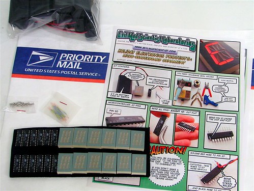
As if the kits were not cool enough, the (2) loose components arrived taped to a vintage unused programming punchcard.
Gotta love it!
Thanks evil Mad Scientist. Your not as Evil as they say.
I got my 3 kits today! I soldered one up during lunch and only had one slight problem. I didn’t have a good solder joint on one pin, so I tracked down the LED datasheet to figure out where to look. A little more heat and solder did the trick and it’s working great!
I can’t wait to finally get all my stuff out of the garage and setup a workspace so I can start playing with stuff like this. I’ve been seeing tons of microcontroller projects lately and can’t wait to start my own. I’ve read through the source code, but any pointers on good tutorials?
I’m glad to hear it! As a reminder, I’ve collected the technical data for
these projects here, including pin locations and links to the
datasheets.
I can’t say that I’ve been terribly impressed with the tutorials that I’ve
seen, and so I can’t really recommend any of them. But, since you’re
happy to track down datasheets to check pinouts and you are
(voluntarily) reading source code, you’re clearly ready to dive right in
without a formal tutorial. If you don’t already have an AVR programming
setup, you might want to get one– and you might need a tutorial for that
part. I have a few pointers about where to start in the main article. (I
strongly recommend using a USB programmer and avr-gcc for
programming, no matter which platform you are using.)
Once you are able to program a chip, your best bet is to take an existing
program– a set of sample code– that you understand, and begin to
modify it. Something like the readerboard project is an excellent place
to start; you can begin by making simple changes like the text strings, but
you can move on from there to animation and then to much more
interesting things. One thing that you’ll want to do is get a few chips to
play with (ATtiny2313’s are cheap!) and install sockets on your target
board– which could be the back of an alphanumeric LED display, for
example.
I’ve already looked through your programming posts, so I’ve started thinking about that. I also have some ideas for modifying the Christmas Ornament project. I bought three of them for just that reason. I put one together as is and will play around with the other two. My first idea is to add a DIP socket instead of soldering the chip directly, to make it easier to experiment with.
Have you done any programming of PIC devices from microchip.com? I’m assuming I’d need different hardware/software to program them. I’ve seen them used in one of the projects I really want to try, a Hard Drive clock. Of course, another guy used the ATmega32 for his HD clock…..
Also, are there any kind of simulators for testing code before I am able to get a programmer set up? I’d really love to start playing around.
Thanks!
Obviously both PIC and AVR are capable of running something like the
hard drive clock. Unless you really want to maintain setups for
both PIC and AVR, however, I suggest that you do a careful comparison.
Ladyada has a great PIC vs. AVR smackdown, and if you’ve seen her
projects based on both, you might give it your consideration. There is
some weirdness in the PIC memory architecture, but the most important
difference (so far as I’m concerned) is that the AVRs have much better
tools and support from the open-souce community. And, since you’ll be
spending your time programming, the tools make a
big difference.
There are indeed simulators out there. For projects with a lot of LEDs,
I find that I rarely have trouble debugging, because it’s clear what’s going
on. Regardless, you can Google “avr simulator” and you’ll find a bunch.
The top hit is AVR Studio 4, Atmel’s windows-
based IDE, which uses avr-gcc and includes a simulator.
Great! Thanks for all the pointers. Since my last comment I’ve been looking at both PIC and AVR specs on their websites, and see that they’ve pretty comparable capabilites. It looks like I have some reading and research to do in the next few months while finally getting rid of all the moving boxes from the garage.
I’ve also just found the Atmel Applications Journal, with archives on the
Atmel website. I’ve glanced through the first issue and complete the 1st novice intro using assembly. It’s pretty decent and my college assembly language class is coming rushing back!
There seems to be some good info in the journal archives.
I thought you might be interested to know that because of the kits I ordered, I decided to jump headlong into AVR programming. I bought an STK500 and 8 AVRs in addition to the 2 that came with it.
In the 2 weeks between getting the kits, deciding to order the STK and actually getting it; I’ve been playing around with AVR Studio almost every day at lunch. I’ve really gotten into it, especially working in assembler, which I haven’t done since college.
I’ve made one "improvement" to the ornament.c program. I wrote a check for an external reset (grounding the unused pin) and go into a special demo mode that cycles through all the LED segments in a circular fashion. The only problem is that I had to remove 5 of the predefined strings and also compile it with -Os optimizations to make it fit in the 2K of Flash on the Tiny2313! I’m working on an assembly language version, which should be a fair bit smaller, as I should be able to remove a lot of extra instructions by keeping everything in registers instead of in and out of SRAM.
Thanks again for the great kit and the push it took to finally make me order my first parts.
Thanks, I’m glad to hear it!
I wish that I’d had assembler in college; it’s really a lot of fun.
I finally finished the assembly version to my satisfaction. You can find it at my website. I’ve included a pretty verbose README that explains a lot of what, how and why I did in assembly. Would you believe that everyone I try to explain this to can’t understand that I find this to be fun? :)
I’m going to try to take a short video of it in action, especially the reset login, and make it available in the next day or two.
Cool, but the link doesn’t seem to be working just yet…
It’s up there now. I forgot to move the zip file into the right directory.
Hey, very nice! I particularly like the switch for common anode/common cathode. *I* should have thought of that!
It’s a tough choice, when distributing kits with the code, whether to use assembly or C. While the assembly version will usually faster and smaller, it’s easier for *most* people to modify the C code, so that’s how I wrote it.
Very true, and your C code helped me understand assembly on the AVR.
I forgot to point out that one of the first things to go was the interrupt table, which is a good couple of dozen bytes at the very beginning of the program. Since there’s nothing going on but a reset, it’s completely unneeded.


As if the kits were not cool enough, the (2) loose components arrived taped to a vintage unused programming punchcard.
Gotta love it!
Thanks evil Mad Scientist. Your not as Evil as they say.
I got my 3 kits today! I soldered one up during lunch and only had one slight problem. I didn’t have a good solder joint on one pin, so I tracked down the LED datasheet to figure out where to look. A little more heat and solder did the trick and it’s working great!
I can’t wait to finally get all my stuff out of the garage and setup a workspace so I can start playing with stuff like this. I’ve been seeing tons of microcontroller projects lately and can’t wait to start my own. I’ve read through the source code, but any pointers on good tutorials?
I’m glad to hear it! As a reminder, I’ve collected the technical data for
these projects here, including pin locations and links to the
datasheets.
I can’t say that I’ve been terribly impressed with the tutorials that I’ve
seen, and so I can’t really recommend any of them. But, since you’re
happy to track down datasheets to check pinouts and you are
(voluntarily) reading source code, you’re clearly ready to dive right in
without a formal tutorial. If you don’t already have an AVR programming
setup, you might want to get one– and you might need a tutorial for that
part. I have a few pointers about where to start in the main article. (I
strongly recommend using a USB programmer and avr-gcc for
programming, no matter which platform you are using.)
Once you are able to program a chip, your best bet is to take an existing
program– a set of sample code– that you understand, and begin to
modify it. Something like the readerboard project is an excellent place
to start; you can begin by making simple changes like the text strings, but
you can move on from there to animation and then to much more
interesting things. One thing that you’ll want to do is get a few chips to
play with (ATtiny2313’s are cheap!) and install sockets on your target
board– which could be the back of an alphanumeric LED display, for
example.
Have fun!
—
Windell H. Oskay
drwho(at)evilmadscientist.com
http://www.evilmadscientist.com/
I’ve already looked through your programming posts, so I’ve started thinking about that. I also have some ideas for modifying the Christmas Ornament project. I bought three of them for just that reason. I put one together as is and will play around with the other two. My first idea is to add a DIP socket instead of soldering the chip directly, to make it easier to experiment with.
Have you done any programming of PIC devices from microchip.com? I’m assuming I’d need different hardware/software to program them. I’ve seen them used in one of the projects I really want to try, a Hard Drive clock. Of course, another guy used the ATmega32 for his HD clock…..
Also, are there any kind of simulators for testing code before I am able to get a programmer set up? I’d really love to start playing around.
Thanks!
Obviously both PIC and AVR are capable of running something like the
hard drive clock. Unless you really want to maintain setups for
both PIC and AVR, however, I suggest that you do a careful comparison.
Ladyada has a great PIC vs. AVR smackdown, and if you’ve seen her
projects based on both, you might give it your consideration. There is
some weirdness in the PIC memory architecture, but the most important
difference (so far as I’m concerned) is that the AVRs have much better
tools and support from the open-souce community. And, since you’ll be
spending your time programming, the tools make a
big difference.
There are indeed simulators out there. For projects with a lot of LEDs,
I find that I rarely have trouble debugging, because it’s clear what’s going
on. Regardless, you can Google “avr simulator” and you’ll find a bunch.
The top hit is AVR Studio 4, Atmel’s windows-
based IDE, which uses avr-gcc and includes a simulator.
—
Windell H. Oskay
drwho(at)evilmadscientist.com
http://www.evilmadscientist.com/
Great! Thanks for all the pointers. Since my last comment I’ve been looking at both PIC and AVR specs on their websites, and see that they’ve pretty comparable capabilites. It looks like I have some reading and research to do in the next few months while finally getting rid of all the moving boxes from the garage.
I’ve also just found the Atmel Applications Journal, with archives on the
Atmel website. I’ve glanced through the first issue and complete the 1st novice intro using assembly. It’s pretty decent and my college assembly language class is coming rushing back!
There seems to be some good info in the journal archives.
I thought you might be interested to know that because of the kits I ordered, I decided to jump headlong into AVR programming. I bought an STK500 and 8 AVRs in addition to the 2 that came with it.
In the 2 weeks between getting the kits, deciding to order the STK and actually getting it; I’ve been playing around with AVR Studio almost every day at lunch. I’ve really gotten into it, especially working in assembler, which I haven’t done since college.
I’ve made one "improvement" to the ornament.c program. I wrote a check for an external reset (grounding the unused pin) and go into a special demo mode that cycles through all the LED segments in a circular fashion. The only problem is that I had to remove 5 of the predefined strings and also compile it with -Os optimizations to make it fit in the 2K of Flash on the Tiny2313! I’m working on an assembly language version, which should be a fair bit smaller, as I should be able to remove a lot of extra instructions by keeping everything in registers instead of in and out of SRAM.
Thanks again for the great kit and the push it took to finally make me order my first parts.
Thanks, I’m glad to hear it!
I wish that I’d had assembler in college; it’s really a lot of fun.
—
Windell H. Oskay
drwho(at)evilmadscientist.com
http://www.evilmadscientist.com/
I finally finished the assembly version to my satisfaction. You can find it at my website. I’ve included a pretty verbose README that explains a lot of what, how and why I did in assembly. Would you believe that everyone I try to explain this to can’t understand that I find this to be fun? :)
I’m going to try to take a short video of it in action, especially the reset login, and make it available in the next day or two.
Cool, but the link doesn’t seem to be working just yet…
—
Windell H. Oskay
drwho(at)evilmadscientist.com
http://www.evilmadscientist.com/
It’s up there now. I forgot to move the zip file into the right directory.
Hey, very nice! I particularly like the switch for common anode/common cathode. *I* should have thought of that!
It’s a tough choice, when distributing kits with the code, whether to use assembly or C. While the assembly version will usually faster and smaller, it’s easier for *most* people to modify the C code, so that’s how I wrote it.
—
Windell H. Oskay
drwho(at)evilmadscientist.com
http://www.evilmadscientist.com/
Very true, and your C code helped me understand assembly on the AVR.
I forgot to point out that one of the first things to go was the interrupt table, which is a good couple of dozen bytes at the very beginning of the program. Since there’s nothing going on but a reset, it’s completely unneeded.