Category Archives: Engineering

WaterColorBot Goes into Production

This has been a busy and invigorating week at WaterColorBot HQ, as we’ve finalized the hardware design for the WaterColorBot and begun in earnest the manufacturing process.

That term “finalized” carries a lot of weight with us. It marks the end of a seven month period of making regular iterative improvements to the WaterColorBot design. When we launched our Kickstarter campaign back in July, we had thought that we were already done with the process. However, it turned out that having these two extra months between launch and shipping gave us an invaluable opportunity to refine and finesse many of the little details that we had already spent so much time on.

Here are some of the highlights of that process; some subtle yet wonderful little improvements that we’ve made to the WaterColorBot.


An improved brush lift mechanism

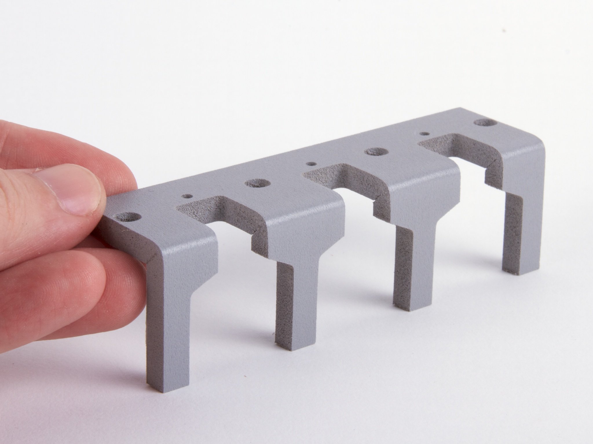
Since we started the project, the carriage on the WaterColorBot has been refined through over 30 revisions, including a half dozen or so just since we launched our Kickstarter campaign in July. Some of these revisions have been minor (for example, rounding the corners more to make it more finger friendly, or tweaking the tolerances on the guide bushings).

Other revisions have been more substantial. In the last few revisions, we changed the way that the brush-lift servo motor actually lifts the brush. Previously, the motor directly pushed the brush holder up or down. But there is now a little stainless steel wire form that transmits motion from the motor to the brush holder. By adding it, we’ve made it so that the brush has a full 3/4” (19 mm) of travel– up from 1/2” (12 mm) –making it possible to push the brush down lower to better wash between changing paint colors, and to go up higher, more readily clearing paper and paint.


An improved lower deck 


The lower deck of the WaterColorBot, affectionately known as the “spoilboard” is machined from medium-density fiberboard (MDF), with indentations to index the paint set and water dishes, and a clip to hold the paper. In WaterColorBot 1.0, we’ve moved from 1/4” to 3/8” thick MDF, making it tougher, more substantial, and better weighted. We’ve also added new laser-engraved indexing marks that show you where to position other sizes of paper (US letter and A4), in case you’re not using 9×12 watercolor paper.

On a related note, we’ve also been developing an alternative plastic spoilboard as an add-on accessory, which may be helpful for artists who like to paint on soaking-wet paper.


Better bearings, yet again

And finally, one last upgrade to the motion control system. As you may recall, the carriage that holds the brush is moved by cords driven by stepper motors. After upgrading to the Spectra cord last month, we found that we could make a further improvement in the overall performance of the robot by replacing three specific plain-bearing stainless steel pulleys with miniature ball bearings. Those three places are the three locations on the WaterColorBot where the cord is directed in a U-turn (for example, at point ‘E’ above). Without the ball bearings, the friction at those three points can potentially be significant, particularly if the cord is operated under tension. And with the ball bearings, the robot can run faster and smoother, with lower current to the motors.


The WaterColorBot kit is now available for pre-order at the Evil Mad Scientist Shop.


Basics: Base Resistors on Transistors

highside-good

Our reader Jon wrote in with a question about our open collector tutorial:

I really appreciated the tutorial, and I was able to follow along and understand it very well. One question I had was – what is the purpose of the 1 kilo-ohm resistor that is connected to the base of the PNP transistor? Because when the open collector is ‘high’ then the base of the transistor is at 12 V and it appears the 1 kohm resistor didn’t affect anything, and then when the open collector goes ‘low’ then the base is connected to ground through the output of the SN7407. So basically, what would the difference be if there was no 1 kilo-ohm resistor at all?

And, that’s actually an excellent question, about something that we usually gloss over.

The short answer is that this is a “base resistor” that we use to limit the maximum current that flows through the base of the PNP transistor.  But, let’s take a look in a little more detail, and see what would happen if we didn’t have that there.

Continue reading Basics: Base Resistors on Transistors

Atmel Maker Community Panel

This week is Maker Week in New York, and on Friday, September 20, Windell will be moderating the Atmel Analyst Panel: The Maker Community and Education. Panelists will include Massimo Banzi of Arduino, Quinn of QTechKnow, Reza Kazerounian, Bob Martin and Sylvie Barak of Atmel, Brian Jepson of Make Books and AnnMarie Thomas of the University of St. Thomas. The event will be at the Hilton Manhattan East at 11:00 am, and walk-ins are welcome. You can contact pr@atmel.com for more information about attending.

OHS 2013 Highlights: DropBot

DropBot is an open source Digital Microfluidic (DMF) automation system that was presented at the 2013 Open Hardware Summit by Ryan Fobel of Wheeler Microfluidics Laboratory at the University of Toronto.

In DMF, discrete fluidic droplets are manipulated on the surface of an array of electrodes coated with a hydrophobic insulator.

It extremely exciting to see the sciences embracing open hardware in new ways.

Car Drives WaterColorBot?

At the recent Boing Boing Ingenuity Conference in San Francisco, Super Awesome Sylvia and her dad, Tech Ninja teamed up with Joe Grand and Ben Krasnow to use the data stream generated by driving a car to create input for the WaterColorBot. Largest. Brush. Ever.

Over at Boing Boing you can read more about their hack, which took grand prize for the hack day.

Making the Legs for the 555 Kit

555 Legs 1

This past week we introduced our “Three Fives” discrete 555 timer kit, which comes with a set of “legs” to make it look like a (DIP packaged) integrated circuit. In that introduction, we mentioned that the legs are machined and formed from PVC foam. But what exactly does that mean? Here (in gory step by step detail) is how we make them!

Continue reading Making the Legs for the 555 Kit

The “Three Fives” Discrete 555 Timer Kit

555 kit

We’re pleased to announce our newest kit, the “Three Fives” Kit, a kit to build your own 555 timer circuit out of discrete components. Here’s a way to re-create one of the most classic, popular, and all-around useful chips of all time.

The kit is a faithful and functional transistor-scale replica of the classic NE555 timer integrated circuit, one of the most classic, popular, and all-around useful chips of all time. The kit was designed and developed as a collaboration with Eric Schlaepfer, based on a previous version (pictured here), and adapted from the equivalent schematic in the original datasheets for the device.  There have been a few other examples of circuits like these (such as the one that we featured in our article about the 555 contest), but we really like how this one has come together.

555 kit

The kit is designed to resemble an (overgrown) integrated circuit, based around an extra-thick matte-finish printed circuit board. The stand— which gives the circuit board eight legs in the shape of DIP-packaged integrated circuit pins —is made from machined and formed semi-rigid PVC foam.

555 kit

To actually hook up to the giant 555, there are the usual solder connection points, but there are also thumbscrew terminal posts that you can use with bare wires, solder lugs, or alligator clips.

555 kit

One of the really cool things about having a unintegrated disintegrated discrete circuit like this is that you can actually hook up probes and monitor what happens at different places inside the circuit.

555 kit

So that’s our new “Three Fives” Kit (shown above with an original NE555 for scale). It’s not quite as big as our 555 footstool, nor as tasty as our edible version, but it’s a great little circuit, and it’s got legs.

Roundup: Simple LED Projects

SimplePumpkins - 11

We’ve put together a roundup of our simplest LED projects; easy things to put together mostly with a bare LED and a coin cell.

Pictured above, Basics: Simple LED Pumpkins

Headless horseman LED Ghostie

How to hack LEDs into Lego minifigures for Halloween, and LED Ghosties for Halloween

urchin - 13 RoboGames Awards (on)

LED-lit sea urchin shells, RoboGames Awards

5 mm warm white diffused-lens LED Throwies - 03

Picking resistors for LEDs  and Some thoughts on throwies

lanterns - 11

Quick, easy, temporary, and beautiful LED garden lights

toner - 15 Soft Circuit Merit Badge14

Paper Circuitry at Home: Electric Origami, and the Soft circuitry merit badge

EdgeLitCard - 49 Edge Lit Cards

Edge-lit holiday cards and part II, Refining edge-it holiday cards