


The succinct story of a modest little footstool– involving datasheets, cnc routing, laser engraving, plywood, glue, chips, all-thread, angle grinders, mountains of sawdust, dowel rods, spray paint, and a picture of a cat.
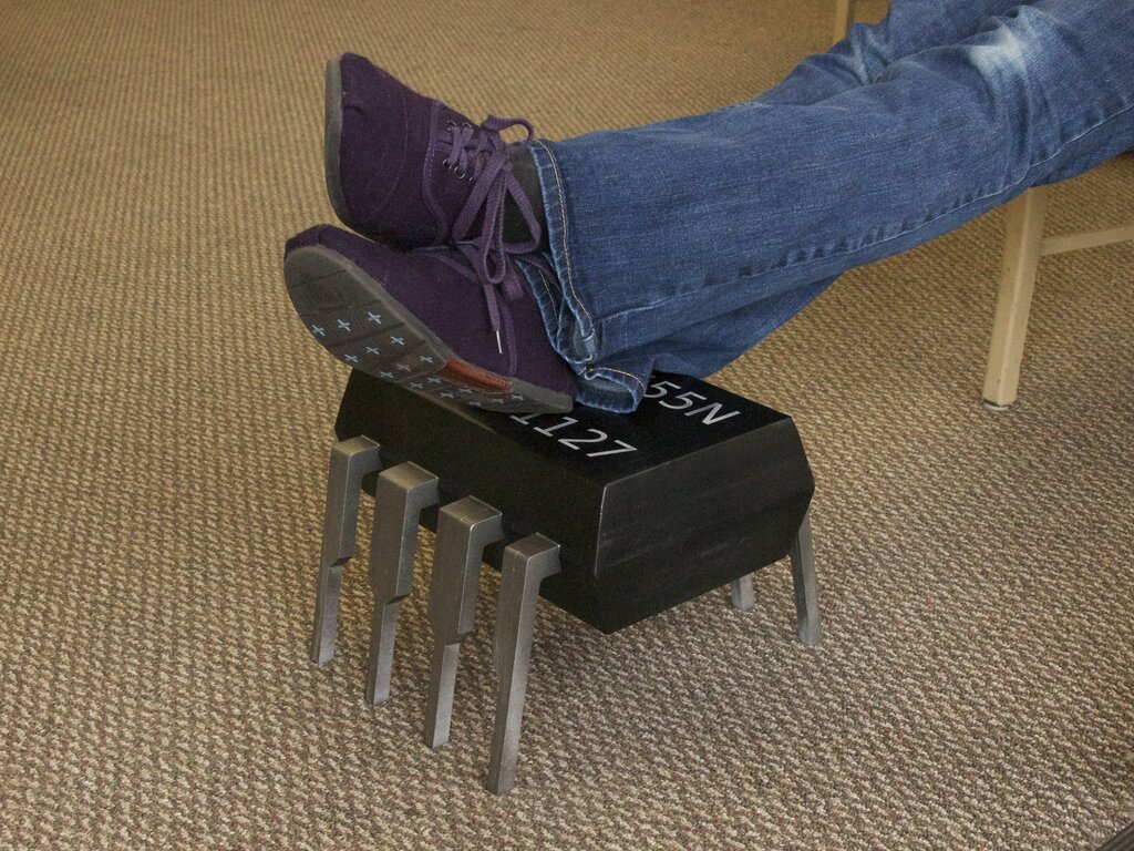
We wanted a new footstool at the lab, and somehow came across the idea of making it in the shape of our hero above, the 555 timer chip.
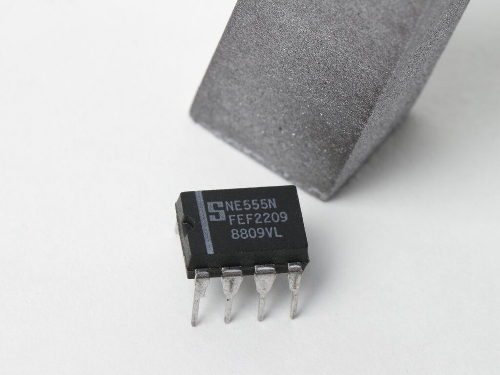
We started our design by looking at the datasheets, and found a few good dimensional drawings that we could scale up. Our model is roughly 30 times actual size at 12 1/2″ long, compared to 0.4″ for a genuine 555 chip. More importantly, it’s a little over 8 1/2″ tall, which we determined to be a good height for a footstool.
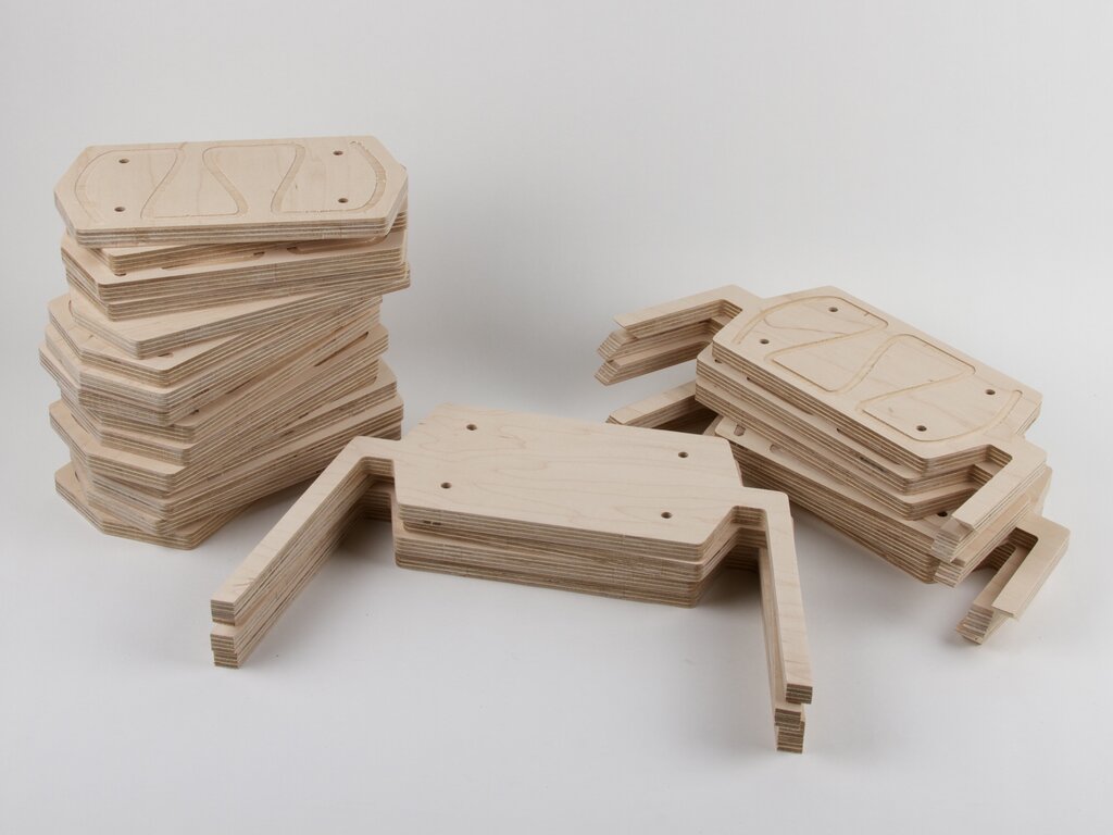
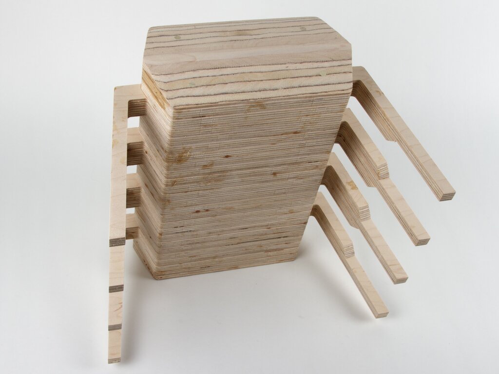
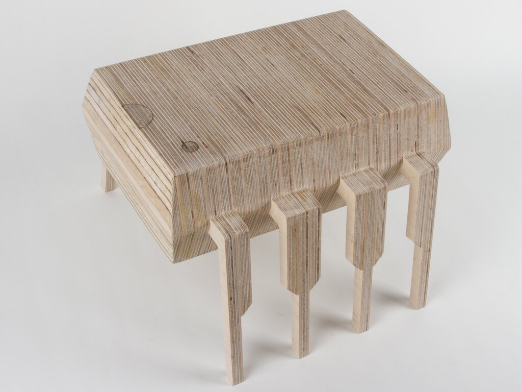
The first stage of construction was to cut out a stack of 1/2″ thick plywood shapes on a CNC router. We used a strong and dense grade of hardwood plywood for this, since there are thin parts that need to be strong. There are 15 elongated hexagons, six with short legs, and four with long legs. Note that every shape has four alignment holes through it.
To get the right lead shape, we sanded down the edges of the “short leg” pieces before laminating them together.
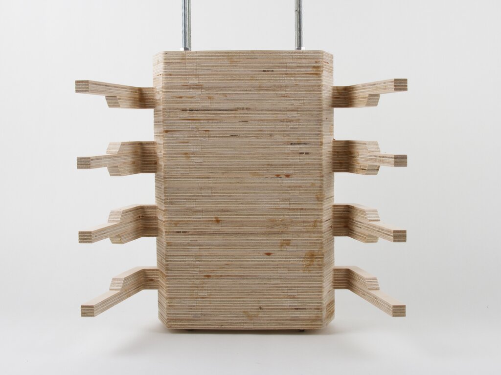
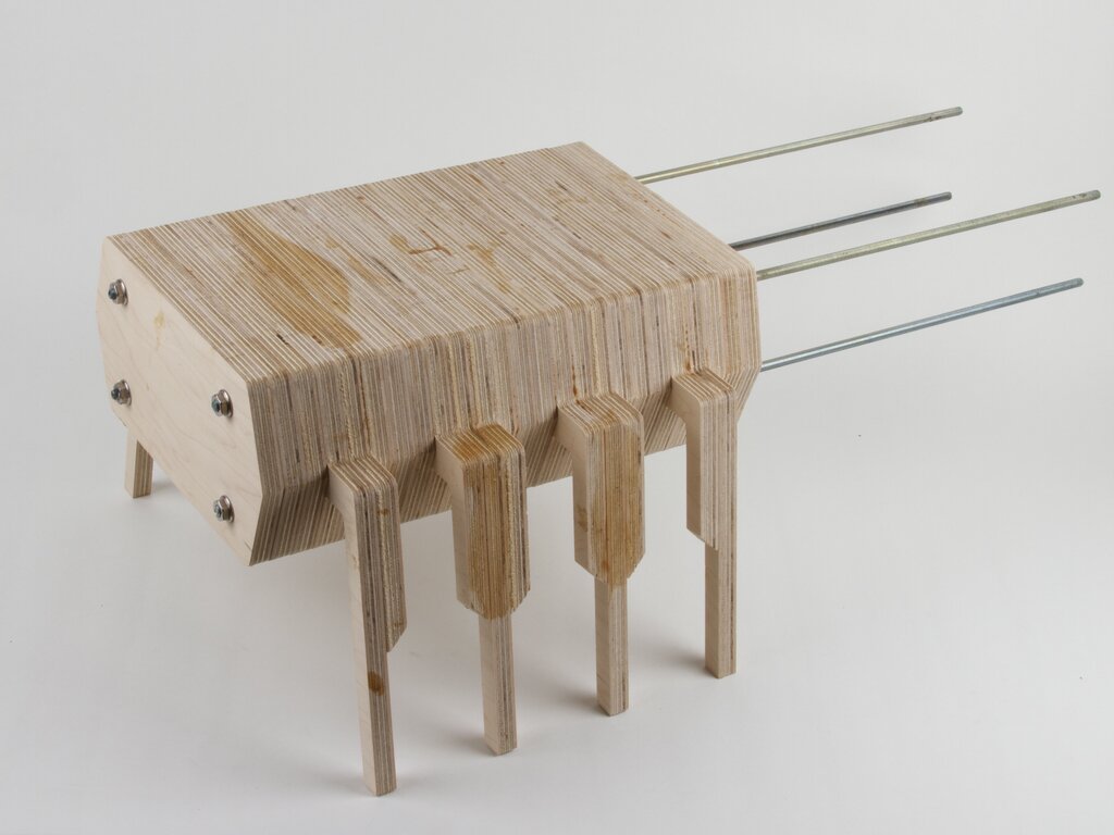
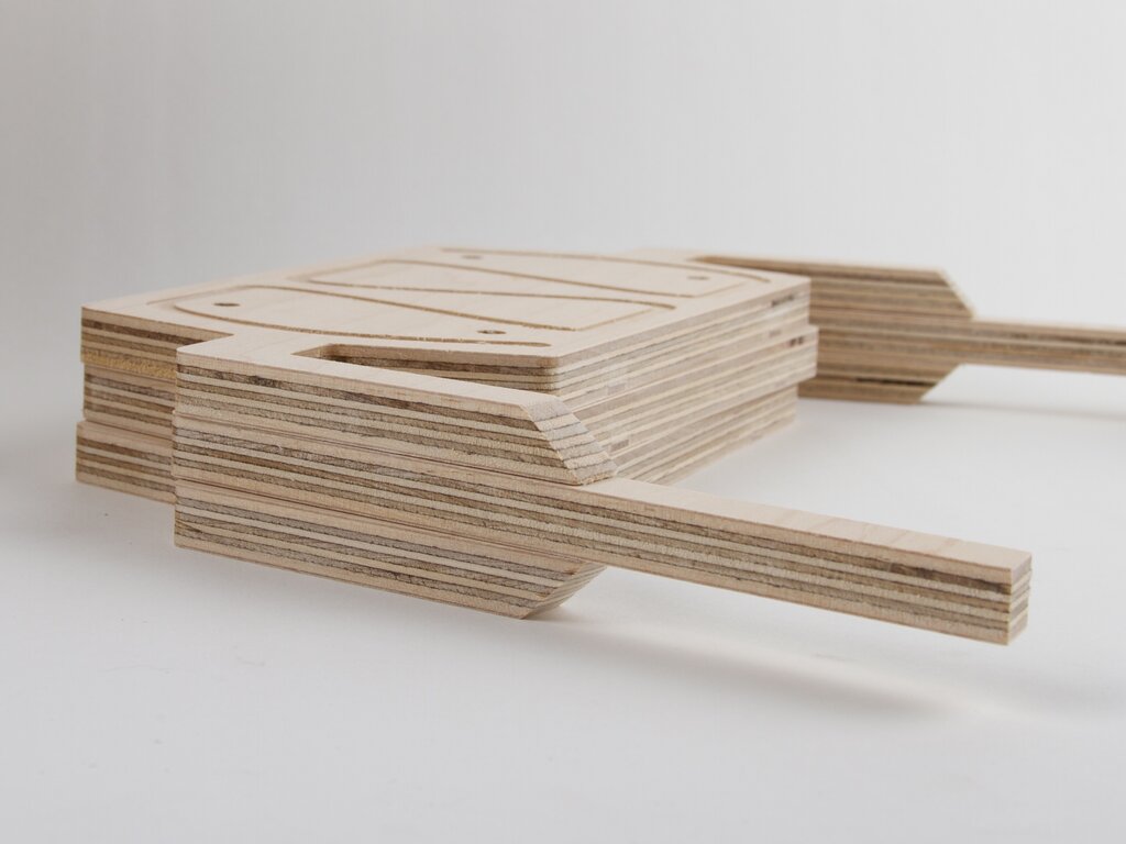
We used long rods of 1/4-20 all-thread to align the 25 shapes into a vertical stack, and bonded them with wood glue. The whole stack was clamped tight for gluing by tightening 1/4-20 nuts on opposite sides of each rod.
After the glue had set, we removed the all-thread and hammered in long 1/4″ wooden dowel rods to fill the holes.
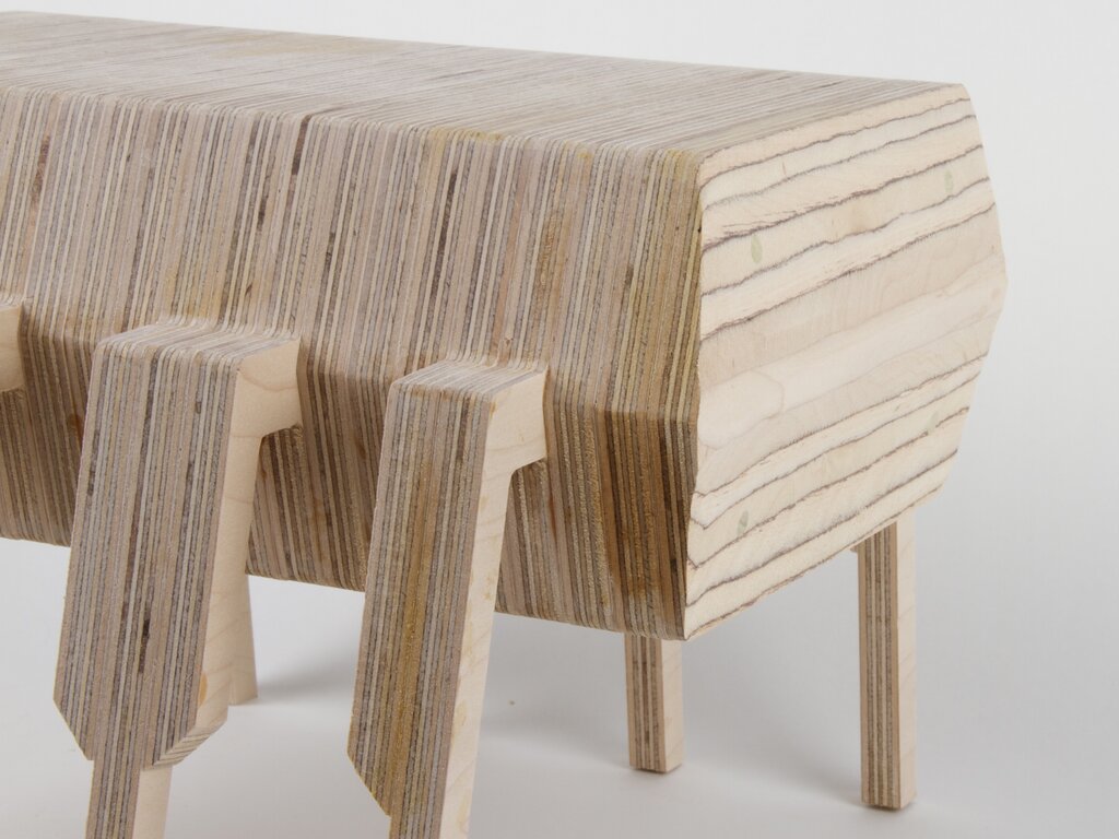
If you look closely, you can see that we angled the end-faces of the chip, including the ends of the wooden dowel rods. To make the angled surfaces, we used an angle-grinder equipped with a sanding flap disc. (This is a highly efficient tool for sculpting wood, but requires a light touch and produces a staggering amount of sawdust.)
We made the polarity-indicating “dot” and “notch” by laser engraving. Next time that we make these, we’re going to engrave deeper or cut those by other means– they aren’t as visible as we had intended.
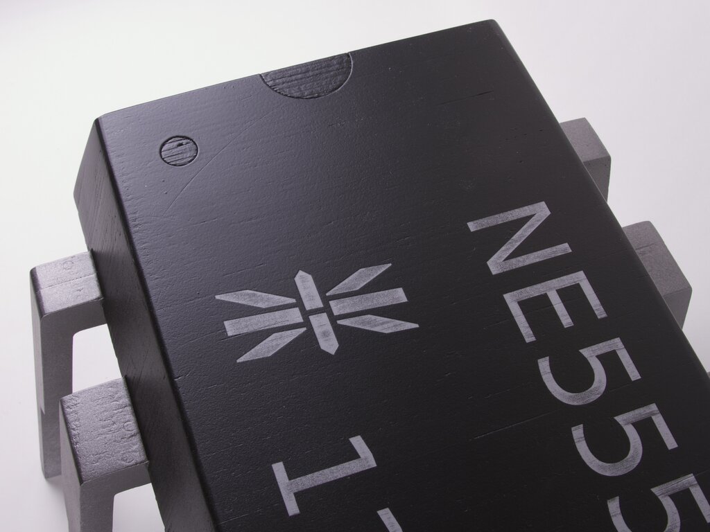
The paint was applied in several layers. First we applied a gray primer coat over the whole chip. We then painted the top and bottom of the main body black.
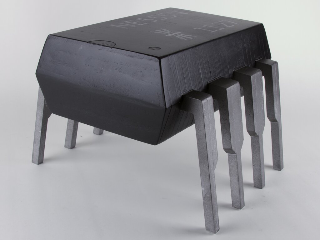
To get the markings on the top, we use a laser engraver to ablate the top layer of black paint, revealing the gray primer below. We then masked off the “black” areas of the body very carefully before painting the legs silver. Once that was all dry, we finished off with a layer of “frosty” matte clear spray paint over the entire surface, giving a better appearance to both the silver and black areas, as well as protecting the engraved area on the top.
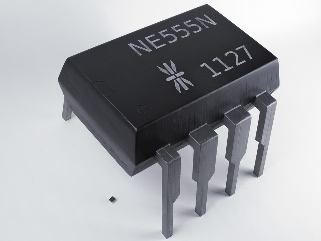
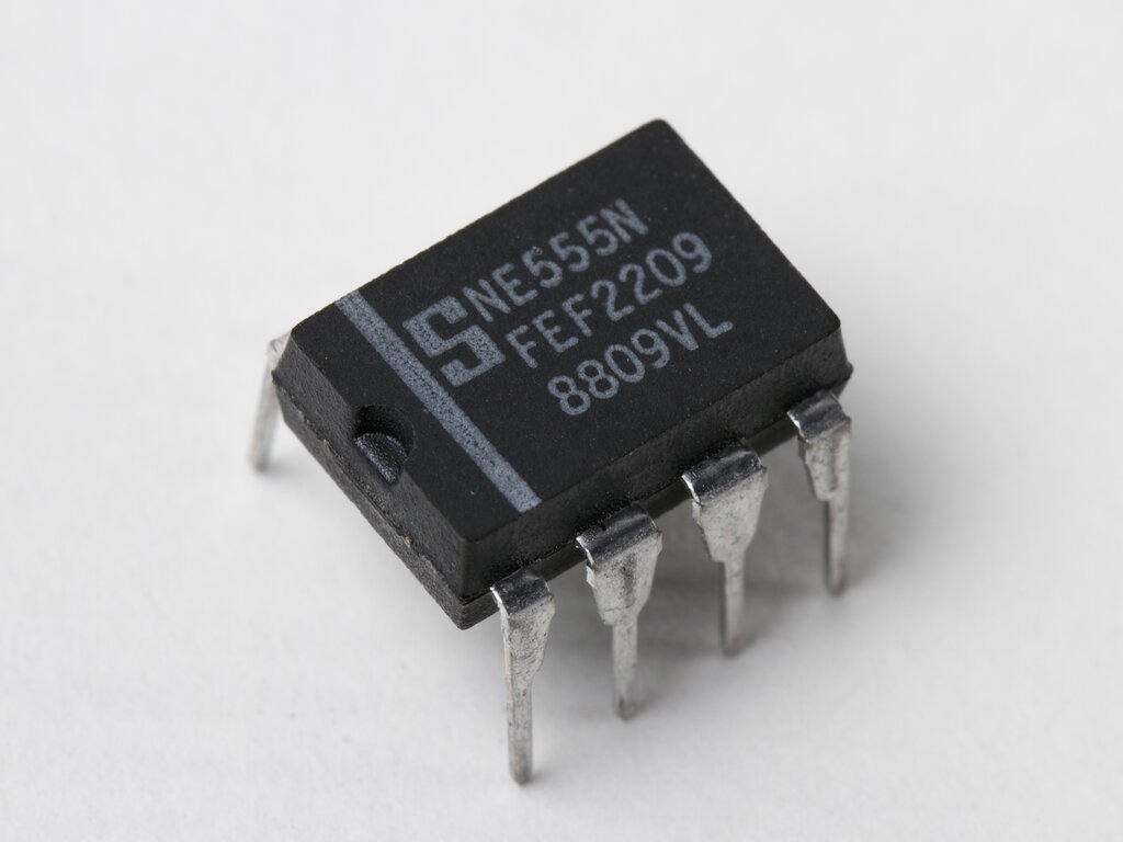
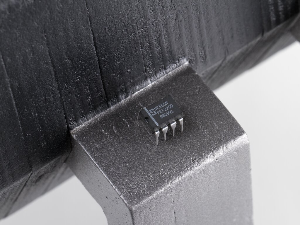
Here, an actual 555 timer chip is shown for scale.
A bit closer in, all you can see is the leg of our chip.
Either our 555 is standing on the shoulders of giants (giant 555s, that is), or perhaps our giant chip just has a chip on its shoulder.
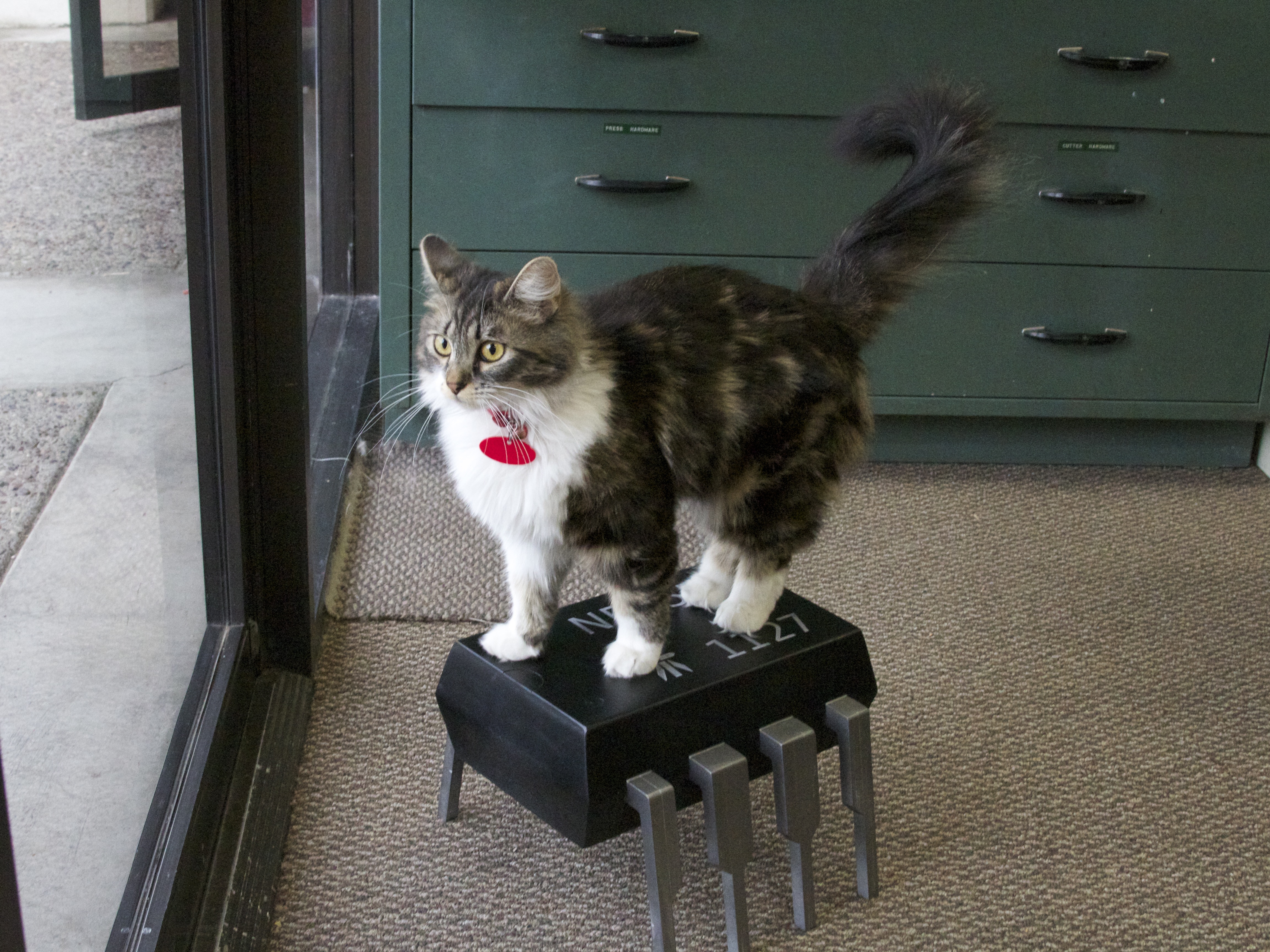
“Measuring 0.9 inches from whiskers to tail, lab-cat Zener is one of the worlds smallest cats.”
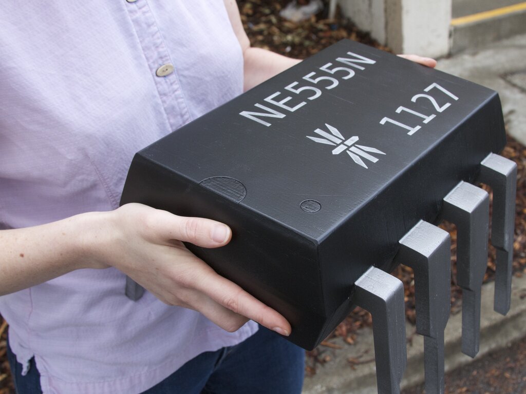
It’s remarkably sturdy and heavy due to the hardwood plywood and laminated construction.

And yet, surprisingly cuddly– almost like it wants to hug you.
All in a day’s work.
…Now all you need is some 6" matrix stripboard & your away!
One slight bit of perniciousness – doesn’t the body extend too far past the narrowed end-pins – doesnt look like you could arrange 2 footstools end to end on the above mentioned stripboard without leaving a gap :)
..I mean pernickety-ness. D**m spellcheck!
What this really needs is some hollow space insideand a bit of fine routing on the legs so that you can put a 555 inside and bring the leads out. Or maybe a microcontroller running really slowly, and the appropriate leds.
I have this image of having little metal pads on the bottom that connect to a 555 chip inside, maybe with some kind of access panel in case you blow it up. Now the gears in my head are spinning…
Do the same thing with various other components and create a huge functioning project with them…
Actually at this scale, instead of embedding a 555 IC one should build a circuit board with the discrete components that make up the 555.
It would be so much more awesome to make a giant, working silicon die with photolithography. You’d probably have to scale up the voltage to drive it, but that is only appropriate.
I second that.
Why not scale up and build a 555 with vacuum tubes inside. It could then serve as a foot warmer, too.
Now that is an Idea!
Wonderful project! It came out great.
Can I ask which CNC router you used?
Oh man, you guys are just getting started with the shop bot and already you’re making awesome stuff. This is spectacular! Great job.
Fantastic! I love it. Except, why didn’t you use proper, original markings, as on the real chip pictured? What was the model? Some Chinese knock-off? Yuck.
Oh, I’m thinking it’s your own symbol. Hmmm. Signetics would have been better. Date code is good though! Until you hit the Y2.1K problem.
The 8-segment * image is the symbol for Evil Mad Scientist Laboratories. Since they were the ones to create the "chip", I’d imagine that they can put whatever "generic" markings they want to on top…
When manufacturing a device, it is appropriate to put one’s own logo and the date code on the top label.
Alternately, when producing artwork, it is appropriate to sign and date it in a manner and location of the artist’s choice.
Either way, we’re in the clear. :D
Windell H. Oskay
drwho(at)evilmadscientist.com
http://www.evilmadscientist.com/
Absolutely superb, from build to presentation!
Beautiful project.
Your final finish would look a lot better if you discovered the use of sanding filler – – you could get rid of all the plywood textures.
Next project for you: an 8088 coffee table!
P4004 would be more appropriate since that was the first Intel microprocessor. They would be end tables. 8008 would be the coffee table and maybe a PLCC or a CLCC table with a resin top would make a great kitchen table. Now what would one model the dining room table after?
W3OHM
Well, if we were chasing "notability" instead of prominence, I think a Zilog chip like the Z8 would be a solid contender… architecture line in continuous production since 1979.
The 4004 was first, but the 8088 brought practical computing to the common man.
Dining room table… Hrm, no chip really fits. Too many legs! Maybe a gigantic, functional, 7-segment LED?
"one of the smallest cats" Oh gosh haha. I think you can definitively say it is the smallest cat :P
Love it!
It would be awesome to have something blinking in it too, using a 555, of course.
Where do we sign up for the pre-order of the first production run?
That totally makes me wish I had a workshop. -sigh-
Wow, this is awesome! Now I want one.
Also I love that your cats name is Zener. Seems appropriate.
Nice!
If you ever make a second version of this, you could have it open up so you get some storage space inside – and the circuit diagram for the 555, of course! (Or even better – a microscope image of the silicon chip, if you can find it.)
I was also thinking the top might look really good upholstered in black leather. It’s mostly straight lines, so shouldn’t be a huge challenge, beyond the leather stitching itself.
Ooh – any chance of uploading the model and/or the CNC files to Thingiverse?
Metal legs and embed a real 555 or equivalent circuit into it. Making a PCB or breadboard thats capable of mounting the giant IC would be interesting…
is there anyway you could post the schematics that you used for us to make our own?
You should have cut away the middle parts of each piece (except the outer ones): thus the stool would be a lot lighter. You don’t really need such a huge massive of wood for a stool. Also, the original chip’s body is hollow inside as well.
Any evidence of that? I’ve never seen a hollow molded PDIP chip. A ceramic version may have been hollow, but we’ve certainly not modeled that one.
Also, there’s no reason to make it hollow– let alone a compelling reason. Heavy is *good* for a footstool, and the extra area inside gives more surface area for glue to bond. Cutting out the interior just adds cutting time, subtracts strength, and makes it less substantial.
Windell H. Oskay
drwho(at)evilmadscientist.com
http://www.evilmadscientist.com/
Speaking of weight, how heavy did it end up being?
Also, in case you hadn’t already noticed, your project has been linked on the front of Hardocp.com.
Just over 11 lbs.
I have been to the mountaintop and have seen the 555 in person.
http://img535.imageshack.us/img535/3162/555ej.jpg
AND it’s my birthday! Whee! *<):^D
Happy Birthday!
Mine Tomorrow! (Going to the beach!)
You’ll need to bend the pins before it will fit in a socket…
1127 for the date code — saw what you did there. ;)
Seconding the commenter who suggested a hollow interior. Could have cut out the interior portion of each of the full cross section slices and greatly reduced the weight. Alignment would only have required some kind of jig that fit around the outside to line up the layers. (Probably at least as accurate as using all-thread to line it all up.
Yes, conductive paint on the legs and wires run inside to an actual 555 chip would have been entertaining. ;)
Yes, this goes well with the proto board coffee table.
Re-shoot the cat pic with a tilt[1] camera.
[1] http://en.wikipedia.org/wiki/Miniature_faking
How about a pressure sensor on the surface so when you put your feet up it triggers a Cylon voice saying "PROCESSING".
Great job! And great name for a cat lol!
One word: Awesome!
Whoa!!!!!
I Wang One too!!!!
excellent idea. could also turn out to be an excellent gift idea.
Please sell these :). I would really love to have one.
So when are you going to do a 7447 coffee table?
Are ROHS Compliant and extended temperature versions also available?
Love it. Love the fact that you have used a NE555. One of my oldest used IC’s.
I am envisioning an entire living-room filled with furniture modeled after components. When they are placed correctly, they would form a functional circuit. That would be amazing.
is the cats last name diode?
ahha, i love the design of that chip and not to forget the diode too. hehe. keep it up with more creative idea. good job :D
i want one
excellent job!
The dot and notch could have been created with a Forstner bit and wood router with template respectively.
Must be nice to have your own frickin’ lasers!!! Ask Zener to be careful around the frickin’ sharks.
Bob
OMG I want one of these! I think you should start selling them on here. I know visitors to my blog would want to buy them. http://www.dearinternet.net
ok, when are going to do the same with a 68000 CPU!!! Would be as big as a bus!!
If you are not gonna sell them outright, how ’bout making the plans available. Even better if you would supply the CNC file(s)!
Is there any chance that you are in nothern ireland? I am asking because that cat looks really like the cat I had when I was in Belfast!
What a nice one! Can I buy the kit? Please let me know.
What?!? The markings on the 555 need to be dark brown and hardly readable.