


Mod a cheap radio control boat into an RC magnetohydrodynamic vehicle.
This design serves as proof of principle for modding an RC vehicle to run on MHD. Rather than being a performance design, it travels at an astonishing speed of several feet per minute since it uses essentially the same design as our foam-tray MHD boat.
Read on to find out how we made the conversion, what worked and what didn’t, and how we plan to get some speed in the next revision.
[This is the third in a series of three articles on building simple magnetohydrodynamic (MHD) propulsion systems.]


The goal of this project was to mod an existing low-end RC boat into a magnetohydrodynamic boat, to take a lot of the effort (and cost) out of building an MHD-powered craft. What we hoped to inherit from the RC boat was (1) a nicely shaped hull, (2) a steering mechanism, and (3) a radio control mechanism that could be hacked to control the the MHD drive.
We found these three things in a Nikko “Sea Racer”, which was $15 (regular price) at our local Toysaurus.
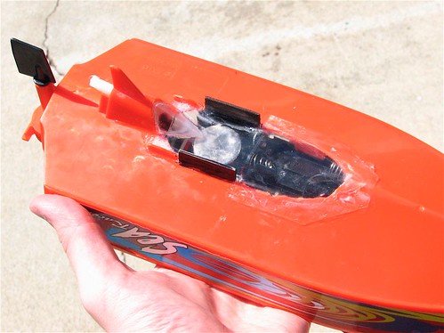
Above left, you can see the original, intact RC boat. It’s even got a propeller. I put batteries in it and tested both the steering and thrust controls, to make sure that the radio control system worked as it should. On the right, you can see how this little machine looks on the inside. The only electronic components on the lid (deck) are the battery pack and the power switch. Everything else is in the hull (the upper part in the photo). From left to right, we have the steering mechanism, which is a gear motor that moves a rudder within a limited range, the drive shaft to the propeller, the thrust motor that turns that drive shaft, and the receiver circuit board (RX PCB).
Having verified that the system basically worked, the next step was to reverse engineer the existing electronics. So, I got out my voltmeter and poked around a little bit. The original system used six AA cells, configured in series and tapped in the middle. Three wires lead from the battery holder to the RX PCB: red, black, and orange. Defining the orange wire as zero volts, the red and black wires are at plus and minus 4.5 volts, respectively. Two wires connected the RX PCB to the steering motor. Again, we want to preserve the radio and steering system while hacking the propulsion mechanism, so this part can all be left alone.
The thrust motor was hooked up to two wires: a blue one connected to zero volts (the middle tap of the battery pack), and a brown wire connected to the RX PCB. When the remote sends the signal to go forward, the brown wire is raised to +4.5V, and for reverse, it goes to -4.5 V. In other words, the “forward” signal connects the motor to 0 V and + 4.5 V, using the first three batteries, while the “reverse” signal connects the motor between 0 V and -4.5 V, using the other three batteries. (This alone would a good hint that it’s a cheapo RC system; any halfway decent reversible DC motor control system uses an H-bridge, switching the motor to run off of the full 9 V, with either polarity.) For what we’re doing, this control mechanism will work very well; all we need is that one control signal that tells us to “go forward.” (Reverse would be nice, but is not particularly important right now.)
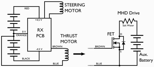
On the left is my reverse engineered diagram of the RC boat’s original wiring. In our modified version, the thrust motor (driving the propeller) will be replaced with a magnetohydrodynamic drive. As in the case of the simple MHD craft, that means that we need a (strong) magnet and a (large) electric current that flows perpendicular to the magnetic field. The original power supply with AA cells is not sufficient to supply the necessary current, so I added a separate auxiliary battery, a small 7-cell (8.4 V) NiMH battery pack intended for a small model airplane.
To switch the potentially massive current for MHD propulsion, I used a FET. I found a suitable one in my drawer, an MTP75N03HDL. That’s an N-channel power MOSFET rated for 75 A and 25 V, with logic-level input and a nine milliohm on resistance. While that particular FET is obsolete, there are hundreds of suitable replacements, such as the IRF3709PBF, $1.86 at Digi-Key. (I do not understand the point of making parts like this obsolete when still competitive in price and performance, especially since there are so many close equivalents.)
To interface the new battery and FET to the radio control system, we essentially want to use the signal (the brown wire) that originally controlled the motor to now control the gate of the FET. In this design, the circuit is completed by the salt water (effectively a resistor), after hooking up the source and drain of the FET as is shown in the diagram to the right. Normally the FET is a good insulator. However, when the radio control signal to go forward is sent, the brown wire goes to +4.5 V, bringing the FET gate 4.5 V positive of the source, and so it starts to conduct, turning on the MHD drive.

Let’s get on to building it. The first step in construction is to remove all the parts of this sea creature that we don’t want. This is a lot like cleaning a fish. And by that, I mean that it’s revolting.
Whereas the seal between the deck and hull is a tidy O-ring, the seal around the drive shaft consisted primarily of a giant pile of grease that had to be scooped out. The gears between the thrust motor and the drive shaft were covered in a different kind of grease. (Yuck!) After removing those and cleaning it up with some alcohol, I used a Dremel tool and a pair of pliers to remove all of the extraneous mounting tabs and ears.


Rather than using quarters for the MHD drive electrodes, I used a couple of soft steel brackets that I cut (with a hacksaw) from an old HP plotter paper tray. I screwed the FET to one of the plates, which not only heat sinks the FET (to a water-cooled fin!) but also establishes the electrical connection to the plate, since the FET’s tab is connected to the drain of the MOSFET. I screwed a standard solder-lug to the other electrode-bracket to make its electrical connection.
To space the electrodes apart correctly, and hold them in place with respect to the magnets, I cut two black plastic brackets from another part of that same paper tray. I glued them together to form the inverted U-shaped form visible on the right. To this bracket, I glued two magnets (1″ diameter X 1/4″ thick, the same type used for the foam-tray MHD boat) and the two electrodes.
That’s it for constructing the magnetohydrodynamic drive; the rest is a matter of getting it into the boat. After hooking up the battery and the gate of the FET, I tested the drive unit (in the kitchen) in a bowl of salt water. The purpose of this was to see which way the thrust would go. In principle, you can reverse the direction of either the electric current or the magnet to flip the thrust, but I had everything glued in place already, so I just wanted to see which way to install my drive unit. In any case, as soon as I hit the “forward” button on the remote, holy cow did the water in that bowl move; it was easily ten times as impressive as the simple MHD demonstration. If nothing else in this project were to have worked, I would have been content just to see that thing go! (Naturally, I was so distracted by the coolness of it all that I forgot to write down which way the water was going– later I had to hook the battery up and try it again, this time armed with my Sharpie.)

Installing the magnetohydrodynamic drive in the boat was a little bit tricky. I started out by cutting a square hole in the bottom of the craft with the Dremel tool as shown here, just large enough to fit the drive unit. I then enlarged the hole significantly so that I could patch it up in a streamlined fashion that would (1) get the magnet as close to the water as possible and (2) not cause way too much drag in the water.


To cover up the hole, I used a thin sheet of clear, flexible plastic (.030 copolyester) from Plastruct. I bent a second piece of it to make a smooth interface to the keel. I sealed the edges with superglue, making an apparently water-tight seal. Constructing and gluing this “glass bottom” took about an hour; I think that it looks pretty good considering that it was such a quick hack.
In the photos you can see the hollow white shaft that the propeller shaft previously occupied. Rather than cutting it off, I just filled it with glue. I’ve also reinstalled the steering motor and mechanism, so the rudder is back in place here.

Here’s the completed MHD system installed and ready to be sealed up. The MHD drive itself sits under the green NiMH battery pack. Since there was no longer room for the original 6-AA battery pack to run the radio and steering, I instead used two sets of four AAA NiCd batteries, purple in the photo. (Each set of four gives 4.8 V, a good substitute for the 4.5 V from three alkalines.)

To test the ship, we filled a giant trough in our driveway with salt water and gently lowered the craft it. Did it move? Yes. Was it impressive? No. It should be called a “Sea Slug,” not “Sea Racer.”
The gentle breeze in our neighborhood was enough to give it pause, and the maximum velocity that we could get in our six feet of travel was only barely enough that the rudder could start to do any steering at all. Clearly, it’s not ready for open water tests in our windy end of the San Francisco Bay. On the bright side, it did work, and it gave us some excellent clues on how to make this a hell of a lot better.
So, why doesn’t it just zip along? There are a number of culprits, but one issue at present is that of scale. When we tested the drive unit alone, the speed was really quite impressive. However, if you put that in a little boat that’s heavy with batteries to the point of riding low in the water, suddenly it’s not enough thrust any more. If the boat were somewhat larger, I could have used one or two cheap high-performance high-capacity RC car batteries that provide more current capability. (More voltage may also help, depending on the salinity of your water. ) The boat that I used is really quite small, and doesn’t have much extra displacement to accommodate modifications.
- First lesson learned: You’re gonna need a bigger boat.
The second thing that I observed is that the pattern of electrochemical etching on the electrodes was fairly uniform. While we might imagine the electrical current as running in a straight line between the two electrodes, it turns out that current was flowing (more or less) out from one electrode in every possible direction, in a great diffuse path towards the other electrode. Since only a small portion of that path was in the strong magnetic field, the resulting force was rather weak. To fix that, the electrodes should be fairly close together and insulated on all sides except the one facing the other electrode. That should encourage the electrical current to flow in the preferred direction.
- Second lesson learned: The electrode design matters.
Finally, the magnetic field itself is somewhat suspect in this simplistic design. Because the electrodes themselves were ferromagnetic, they significantly distorted the field lines, reducing the volume of relevant space where the field lines could be essentially perpendicular to the direction of electrical current. A straightforward way to a get moderately large volume with a strong and uniform magnetic field is to surround the region with two parallel permanent magnets. It would be worth the effort.
- Third lesson learned: Use nonmagnetic electrodes, arrange magnets carefully.
Putting it all together, a good design for the next version would be to start with a larger craft that can carry one or two RC car batteries. The MHD drive should be designed around a rectangular or square tube geometry, where salt water passes through the tube. The electrodes should be parallel and sit on opposite walls of the tube, perpendicular to the magnetic field orientation.
So, I’m ordering some new magnets (my old ones got glued in to this one) and I’ve started looking for a new RC boat to modify. Hopefully, with the redesign, it will be tough enough to cruise out in the bay.

Hi Dr. Who!
I recall reading back between 1988 and 1992 that Mitsubishi Heavy Industries was experimenting with MHD and had built an expensive 90 or 100 foot boat. I seem to recall that they had two water-flow pipes (parallel, running the length bow to stern) similar to what you mentioned as a possible improvement to your RC MHD boat here– to have sea water flow through a pipe or pipes with the magnets and electrodes appropriately located. The striking thing was, the ship was typically gorgeous, big money RD lab show off gorgeous, but like your experimental RC MHD here, it was s l o w. Like, yes, we are really moving under power, fool, the wind is not even blowing this way! :) I remember being excited at the concept and their determination to improve the design and speed and make a viable technology out of it and looked forward to the day. Here it is, 2006, so I take it they have not had much success with that as yet or we’d have heard about it.
Gen Aris
That’s right. According to the wikipedia pages on MHD propulsion
and the Yamato 1,
the MHD drive was a real flop in the tests, only reaching 15 kph. I,
however, would be very happy to achieve 15 kph in a small-scale
RC-MHD model!
—
Windell H. Oskay
drwho(at)evilmadscientist.com
http://www.evilmadscientist.com/
To help with some of your weight issues on the boat, I would suggest using Lithium Polymer or Lithium Ion batteries. A good assembled Li-Po/Li-Ion pack runs just a little more than a Ni-Mh pack of the same physical size and capacity but with over half the weight and more voltage. As far as a larger hull, if your budget can support it I would suggest the ProBoat ShockWave 26. It’s a full ready-to-run 26" long Deep-V that runs about $140 at http://www.horizonhobby.com (and probably any HobbyTown USA retail store). I figure that should cover what you are looking for in your next project. If the ProBoat is out of your price range, then you’re probably going to have to find a larger Nikko to suit your needs, because I don’t know of any boats off the top of my head that are cheaper but of similar size to the ProBoat.
Hope this helps you out.
When you remove power from an inductive load, the magnetic field around the load collapses, producing a BACKWARDS flow of current. The diode, which may or may not be integral to the FET (depends on the kind of FET you use), is there to shunt this backwards current safely back into the load, so that it doesn’t damage the rest of the circuit.
Note that FETs aren’t unique in needing these diodes. Bipolar transistors, often used as relay drivers, will often have reverse-biased diodes hanging off their collectors (or emitters in the case of PNP transistors) for the same reasons.
Firstly, I am very new to the "creation of electronics" world, or, modding and such. My question is why you have a diode between the source and drain of the FET. I am asking because i’m trying to build a switch that uses a FET to control a high powered motor with a low voltage remote control car pcb.
Thanks
That diode is *part* of the FET– this is a common feature of MOSFETs. Drawing it as part of the symbol helps remind you that if the voltage is biased the other way, the diode conducts, and the FET no longer can control the current that flows.
—
Windell H. Oskay
drwho(at)evilmadscientist.com
http://www.evilmadscientist.com/
Why you don’t use two pieces of printed circuit board, not veroboard, as electrodes?
If you use a single sided the currente will flow only in the field camp and are not magnetic.
And you can solder them to form 90 degrees as the original project and are easy to cut.
As I see you can make the spacer and the electrodes all in one….Instead of two you can make a ‘U’ shaped with a pass-thru to mount the magnet.
I think like that you can lower, tune, the magnet distance to the water.
jorgecunha37@hotmail.com
I wish to clarify a point. When the switch opens in an inductive circuit, the collapsing field of the inductor does not cause a reverse current.
An inductor attempts to KEEP the current flowing through it in the same direction at the same value. (the dual is the way a capacitor tries to keep the voltage across it the same)
Look at it like this. To keep the current flowing, the collapsing field creates a voltage to make this happen. It makes whatever voltage is necessary to keep the current flowing. If you look at a switch and inductive load, it turns out that the VOLTAGE across the inductor does reverse. However, it takes this polarity of voltage to KEEP the current flowing. This has the effect of causing the voltage across the switch to rise "above’ the power supply voltage. Draw a circuit with the switch (FET or whatever) to ground and the inductive load going UP to the power supply.
When this happens, the switch’s breakdown rating can be exceeded. A diode is put across the inductor which conducts, thus limiting the voltage across the switch to just above the power supply. They are called "catch diodes" by us inductive load designers.
When you have two switches, one pulling down (as above) and another one pulling up (for driving current both ways through the load), this switch now needs reverse voltage protection when its companion switch opens. Thus a diode is put across the inductor to prevent REVERSE voltage. Confusing?
It’s easier if you draw out both a "down" and "up" switch. You’ll need two of these pairs to see how to get reversible current. The four switch combo is called an "H Bridge". [like a DPDT switch]
With a good inductor you can get enough voltage to break down air, aka, make a spark. (that’s why you get sparks in motors)
As a young fella, I once had the FILTER CHOKE for a tube type power supply. It was about a six inch cube and had a value something like the better part of a Henry. I was playing around with it and a 6-volt lantern battery and noticed that I could get a pretty good spark from the "inductive Kick" as we called it. The faster I pulled the wire away to open the circuit, the longer the spark was (more voltage). I thought, boy! I bet that’ll make a nifty sound if I put a loud speaker in the circuit. So I put an ordinary eight ohm speaker in series with the choke and battery, However, it was completely QUIET. WHY?
The exponential decay of current in an inductor (and now in the speaker) is very smooth – EVEN THOUGH there is many kV across the air gap in the ionized air spark!
73, Steve, K9DCI at arrl.net
P.S. You figured out the suggestions I would have made about the boat motor…
Slight error in my previous…
About in the middle…
…
When you have two switches, one pulling down (as above) and another one pulling up (for driving current both ways through the load), this switch now needs reverse voltage protection when its companion switch opens. Thus a diode is put across the _transistor_ to prevent REVERSE voltage. Confusing?
…
73, Steve
There is a very simple reason why your own-builded boats are not very fast.
The american prototypes even reached 2 mp/h !!!
The solution is a much stronger magnetical device without resistance against the electric flood.
It’s Superconductivity, but this is a much bigger problem, because you have to cool this down to around -275 °C by helium ;)
well when i get my magnets in I am going to test my own design a rough outline follows:
a length of plastic box tube about 25 times longer than the width. electrodes cut to fit the inside of the tube at the sides one face flat up against the plastic 2 rows of magnets perpendicular to the electrodes on the outside arranged so that the north and south poles face the same way vertically: IE:
NNNNNNNNNNN
SSSSSSSSSSS
tubetubetubetube
NNNNNNNNNNN
SSSSSSSSSSS
so that the magnetic field strength in the working area is as high as possible
with the magnets and electrodes running the length of the tube
this arrangement should allow a high current flow as well as maximized magnetic field strength
I have brass plates on hand i will make the prototype use brass but what should i use on the final design?
any suggestions on design improvement? (also I am using neodymium block magnets rather than a disc magnets as was used in the design in the article to avoid the lower thrust caused by lessening strength as you go further forward and backwards)