Woo-hoo! We got a box of
MakerBeam to keep us busy through the long dark winter evenings. For more info, see their
kickstarter page, and the
google group. They’ve been busy actually getting stuff made, so we’ll forgive them for not updating much lately.
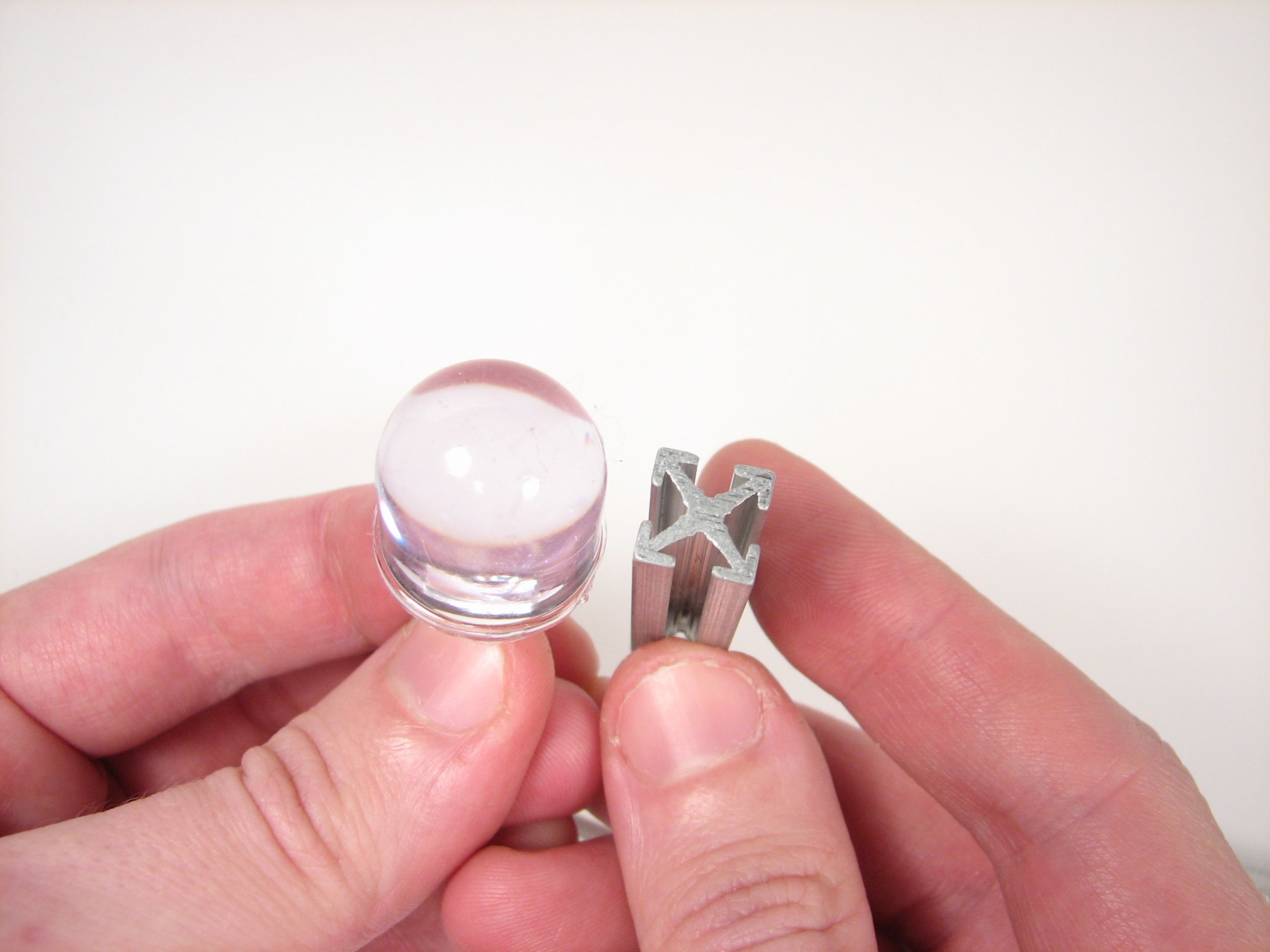
The beam cross section is shown here with an LED for scale.
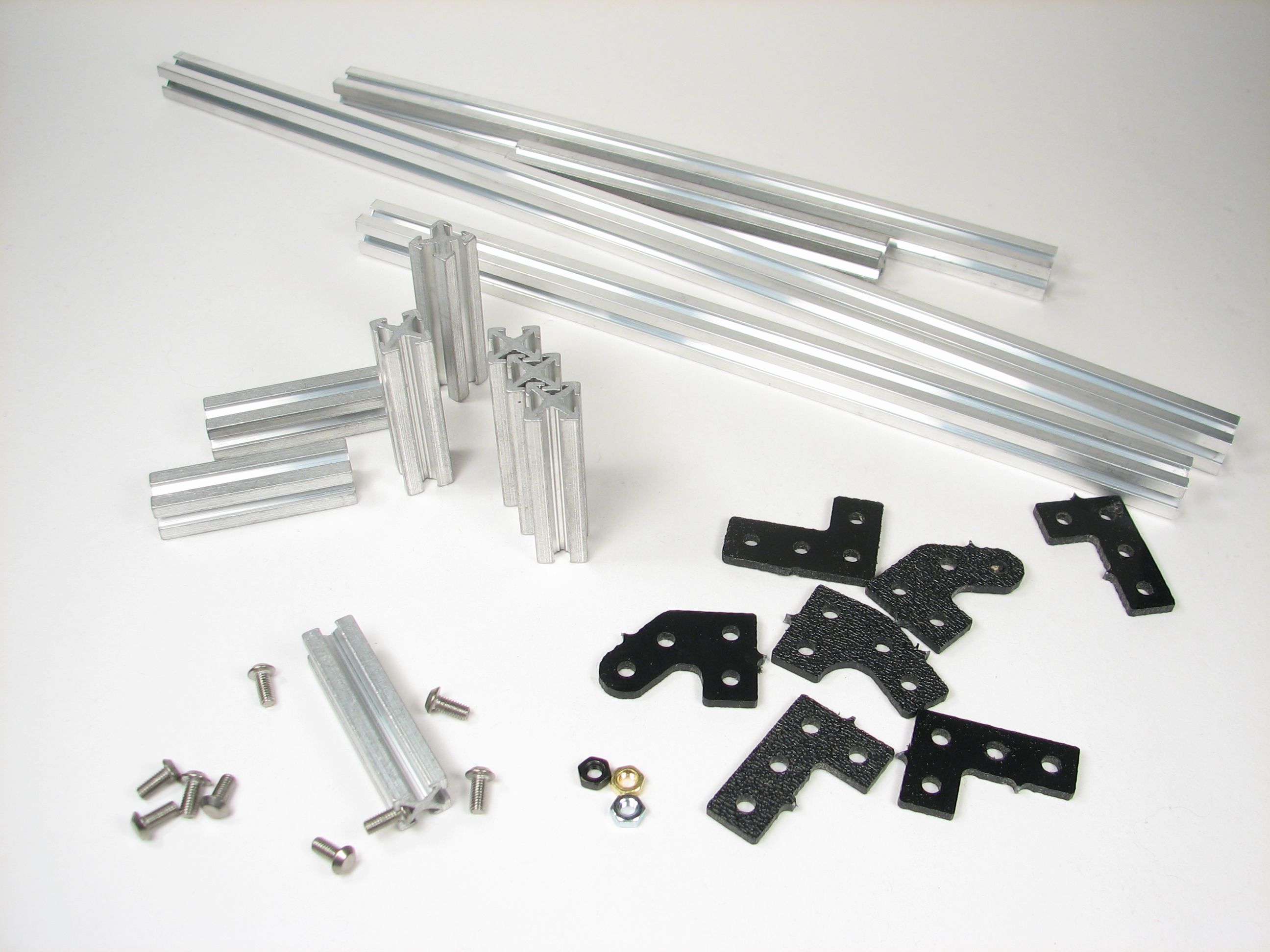
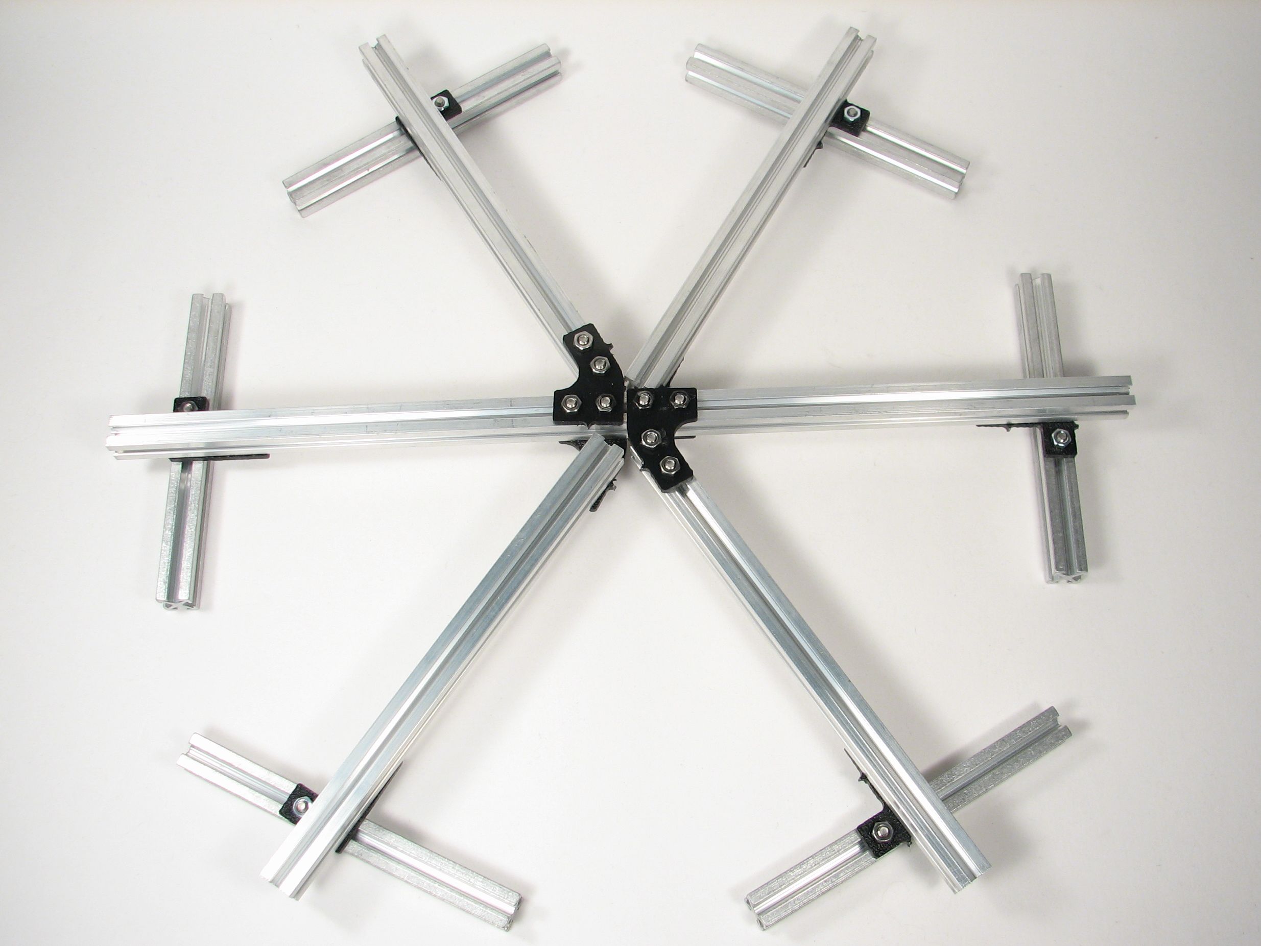
We got several lengths of beam; 45, 60 and 90 degree plastic connectors; fancy screws and assorted nuts. The prototype connectors are made on a shopbot out of ABS.
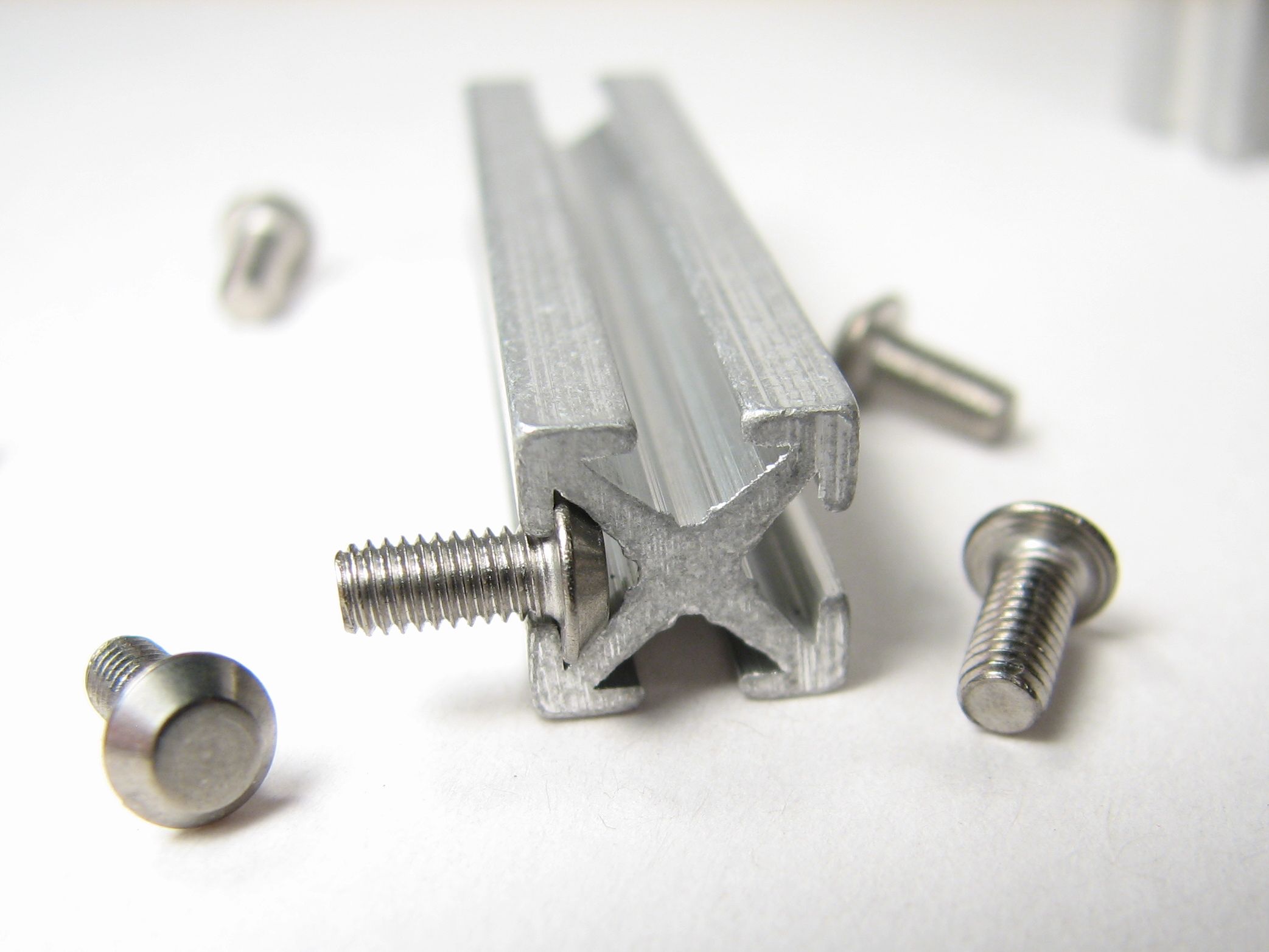
The little screws look funny at first–there’s nowhere to put a screwdriver! They slide nicely into the side of the beam, where you can see that you won’t need a screwdriver for them.


I don’t get why "screw head fits into beam" means I don’t need a screwdriver to put the other end somewhere. The only thing I can figure is that you are supposed to use the beam to drive the screw, but that seems a little unwieldy. What if I’m putting it somewhere tight that I can’t get a whole beam in there?
These screw-like things are used to attach to the brackets with a standard hex nut– really what you need is a small wrench or nutdriver. I think that the final screws will have a squared head so that they can’t rotate in the grooves.
—
Windell H. Oskay
drwho(at)evilmadscientist.com
http://www.evilmadscientist.com/
80/20 uses hex head screws, and you order access holes (for your allen wrench) drilled through the center of the beam. That’s one of the most interesting features of t-slot beams: the center part being compromised by a hole doesn’t matter much since the four edge profiles are still intact. I’m not clear on how the MarkerBeam folks intend to have tight connections with screws facing outwards from the t-slots; facing the other way, square nuts won’t rotate (though you need to make sure the screws are just the right length).
I still don’t get it.
80/20 screws are supposed to go on the outside of the groove, not inside, the special nuts go inside the grooves.
This isn’t 80/20, this is MakerBeam.
—
Windell H. Oskay
drwho(at)evilmadscientist.com
http://www.evilmadscientist.com/
The screw things seem less then optimal. I think something like carriage bolts would work way better. The problem isn’t so much tightening them, it is that they could become impossible to loosen.
http://www.boltnuts.net/Carriage-Bolts-Manufacturer-p96.htm
Yes, that would be better than the existing prototype screws. We’ll see what the final setup is.
—
Windell H. Oskay
drwho(at)evilmadscientist.com
http://www.evilmadscientist.com/
That must be one rather large LED. Perhaps you could pose a standard cat in the picture for scale.
Hmmm. All of our cats are large, too. :P
—
Windell H. Oskay
drwho(at)evilmadscientist.com
http://www.evilmadscientist.com/
So, MakerBeam combined in this way: http://www.cubespawn.com to make pick and place machines, seems like no self respecting mad scientists can live without robotic minions…
And it just got easier to make them!
I have serious doubts about the usability of that profile in any kind of machine (except very small ones).
The section is just a few mm wide, and profile design does little to give good flexural strength.
The conic screws cannot be mechanically blocked in the profile -usually the screws used in this kind of applications are squared to prevent rotation- and must be inserted from the cut of the profile, while most of the commercial T-slot profiles have specially shaped screw heads that can be fitted from the frontal slot opening.
The uneven profile size is prone to extrusion defects and bad linearity: most aluminum profiles of similar shape uses a central hole to ensure better cooling and shrinking. Surface finish does not seem very good too: bad photos or cheap extrusion?
>I have serious doubts about the usability of that profile in any kind of machine (except very small ones).
Yes, it’s designed for small machines. That should be quite obvious. It’s a miniaturized version of larger extruded construction systems.
>The section is just a few mm wide, and profile design does little to give good flexural strength.
It’s about as strong as you’d expect from looking at it, not too bad, actually. Obviously it’s not for heavy-duty applications– it’s skinny aluminum; what did you expect?
>The conic screws cannot be mechanically blocked in the profile -usually the
>screws used in this kind of applications are squared to prevent rotation- and
>must be inserted from the cut of the profile, while most of the commercial
>T-slot profiles have specially shaped screw heads that can be fitted from
>the frontal slot opening.
I couldn’t agree more. I think that these are prototype connectors, and I look forward to seeing what the final design is. This is the "alpha" rev here; beta comes sometime in the next few months.
>The uneven profile size is prone to extrusion defects and bad linearity: most aluminum
>profiles of similar shape uses a central hole to ensure better cooling and shrinking.
>Surface finish does not seem very good too: bad photos or cheap extrusion?
Most aluminum profiles of similar shape are much larger– particularly in the middle– and present much more of a manufacturing challenge with respect to cooling and shrinking. I do like the cases where there’s a hole on the end that can be tapped, though.
The surface finish is okay. Typical extrusion marks, nothing remarkable. The sawing on the ends is a little sloppy, perhaps. You can insult our photos all you like, but the fact remains that you’re looking close up at miniature extrusions that have surface marks on the same scale as other common extrusions.
—
Windell H. Oskay
drwho(at)evilmadscientist.com
http://www.evilmadscientist.com/
> It’s about as strong as you’d expect from looking at it, not too bad, actually. Obviously it’s not for heavy-duty applications– it’s skinny aluminum; what did you expect?
I expected (eagerly) something that could be used to build a small CNC mill.
I made a quick FEM analysis: a 1 meter long bar has almost 5mm displacement when subject to a 10kg force at 3/4 length. That is not acceptable.
With "very small machines" i meant *very* small.
>it’s skinny aluminum; what did you expect
There are plenty of commercial profiles with far better performances, and only a bit larger.
Based on the donation plan listed on the website, most of those profiles are actually cheaper.
>I think that these are prototype connectors, and I look forward to seeing what the final design is.
I am curious too, since the T-slot on the aluminum profile is not suited to host any of the usual bolts shapes.
Wether they have invented a brand new bolt shape, or, more probably, the bolts will have to be inserted from the side. That would be a major drawback.
>Most aluminum profiles of similar shape are much larger– particularly in the middle– and present much more of a manufacturing challenge with respect to cooling and shrinking.
True, and in bigger sections there is plenty of tricks to be used (have I mentioned I work in the aluminum business? :-D).
In a section so small, the only affordable solution to improve shape tolerances is a central cooling hole, and it’s missing here. The hole can be used in a lot of junctions, too.
> The surface finish is okay. Typical extrusion marks, nothing remarkable.
They seems really deep from the photos. Extrusion marks and shears are easier to contain on small profiles, so the markings displayed IMHO are a sign of cheap extrusion.
The quality of the cut is not an issue. On industrial processes, it’s usual to cut 5-20 mm on each end of any extruded bar to fix planarity issues and to remove endings that are often damaged in shipping.
> You can insult our photos all you like
Not my intention, sorry if it sounded so.
>I expected (eagerly) something that could be used to build a small CNC mill.
>I made a quick FEM analysis: a 1 meter long bar has almost 5mm displacement
>when subject to a 10kg force at 3/4 length. That is not acceptable.
Since you seem to be willing to go the distance to complain, perhaps you would be willing apply your skills to constructive analysis as well. How about showing us side-by-side FEM analysis of makerbeam versus the other 1 cm profiles out there, as well as for *solid* 1 cm bar stock? My guess: makerbeam is more like a factor of two and less like an order of magnitude worse than a solid beam.
But back up a second anyway: Why would you possibly expect that hollowed out 1 cm aluminum would be stiff enough to build a CNC machine capable of withstanding significant machining force? There’s a reason that CNC machines weigh a ton (or often, several tons).
I think that this would be fine for featherweight CNC applications– pick and place, additive technologies, plotter, and so forth. If I planned to do actual metal removal– even Dremel scale — I’d *start* by looking at some of the 2-inch profiles, or skip aluminum altogether.
>Based on the donation plan listed on the website, most of those profiles are actually cheaper.
As you said, "donation." I’m not sure what your problem with this is.
—
Windell H. Oskay
drwho(at)evilmadscientist.com
http://www.evilmadscientist.com/
> Since you seem to be willing to go the distance to complain,
Man, we are having a discussion here, not a fight. Please calm down, take a deep breathe and try to understand my point.
I know my english is not excellent, I am not a native speaker.
> My guess: makerbeam is more like a factor of two and less like an order of magnitude worse than a solid beam.
Do you mean that,
* given A the flexural resistance of a solid bar
* given B the makerbeam’s resistance
* given C a generic 10mm T-solt resistance
2C > B > A/10
Really, I can’t understand that sentence.
> Why would you possibly expect that hollowed out 1 cm aluminum would be stiff enough to build a CNC machine capable of withstanding significant machining force?
Because I want to build a 60x60x60 cm CNC mill to work on expanded-extruded polystyrene, with fast rotation of the mill and low speeds.
Without any significant resistance from the material, the only forces to overcome are the inertia on the movements, weight of the tool head and own wight of the structure. That means about 10 kg force, worst case.
My first design used 1” aluminum square pipes, but they are difficult to join properly. I hoped to use the Makerbeam.
I am now considering a 20mm framing system from 80/20 or even the 32mm from Arimetal.
> There’s a reason that CNC machines weigh a ton (or often, several tons).
There’s a reason that CNC machines can mill carbon stell, but *mine will not*.
If I’ll ever need something machined on a proper mill, I’ll just take my drawings to our production department and offer a bottle of wine to the shop owner.
I don’t think it’s a good idea to ask repetitively them to work on my 10-inches Warhammer sceneries on a 6-meters 5-axis machine.
> I’d *start* by looking at some of the 2-inch profiles, or skip aluminum altogether.
Why skip aluminum? You just have to design the frame properly.
> As you said, "donation." I’m not sure what your problem with this is.
The problem is that, with $1,024 you can have
* "at LEAST 50 meters of MakerBeam, plus connectors, during beta release, AND Alpha kit in December."
* or 120 meters of market-proven commercial-level, age hardened 30x30mm profile, with connectors, bolts&nuts, terminals, property certification shipped right to your front door.
I understand it’s a donation, but it’s expensive anyway.
>Man, we are having a discussion here, not a fight.
>Please calm down, take a deep breathe and try to understand my point.
>I know my english is not excellent, I am not a native speaker.
I’m not complaining about your language, nor fighting with you. Your english is fine; I had no idea that you were not a native english speaker.
The *only* thing that you’ve said so far that makes me angry is "Please calm down, take a deep breathe." That was uncalled for.
You should try to understand my point: It’s absurd for you to say that you have calculated makerbeam to have an "unacceptable" degree of flexibility without giving some basis for comparison.
Your claim: Makerbeam is "unacceptable" because a 1 m bar flexes 5 mm at the end when a 10 kg load is applied at 0.75 m.
I repeat my questions– These are fair questions, and do not deserve your ire:
0. How many millimeters does Makerbeam bar deflect under these conditions? (5 mm)
1. How many millimeters does a solid 10 mm bar deflect under identical conditions?
2. How many millimeters does a "good" 10 mm profile deflect under identical conditions?
If you really have a basis for complaint, it should show up in the ratios of those numbers– let’s see those calculations.
If you’re only going to give the one number and say that it’s "unacceptable," then I think that this is misleading. A 10 mm bar does not have zero flex.
(Also, I would be very interested to know which 10 mm profiles you think are better. The only one that I know of is MicroRax, if you know of others as well, please show us your calculations for those too.)
>Really, I can’t understand that sentence.
Is this where I should tell you to "calm down, take a deep breathe and try to understand my point?"
I’m trying to clarify here.
>The problem is that, with $1,024 you can have […] age hardened 30x30mm profile […]
With $1024, our business can help sponsor a new building system that will soon be available for other people.
Or, with $1024, you could buy some existing stuff for yourself. Like extruded aluminum shapes that are already out there. Or a lot of nice chocolate. Or a cheap car. Yes, we know this.
We are doing a good thing here, and you don’t need to knock us — or them — for it.
—
Windell H. Oskay
drwho(at)evilmadscientist.com
http://www.evilmadscientist.com/
> The *only* thing that you’ve said so far that makes me angry is "Please calm down, take a deep breathe." That was uncalled for.
Sorry for that, then. I thought you were upset, my misunderstanding.
> It’s absurd for you to say that you have calculated makerbeam to have an "unacceptable" degree of flexibility without giving some basis for comparison.
I calculated the displacement and deemed it unacceptable *for my needs*
> Your claim: Makerbeam is "unacceptable" because a 1 m bar flexes 5 mm at the end when a 10 kg load is applied at 0.75 m.
Right. That means you can not have a decent control over the Z-axis of the mill, since the simple weight of the milling head and chuck would bend the frame of a significant measure.
I tested the profiles on my frame setup.
Makerbeam: -4.8 mm displacement
Bar: -2.25 mm
Microrax: -4.5 mm
1” square pipe: -0.6 mm
All the calculations were made in SW2010 SimulationXpress, assuming a 6060alloy and with measures quoted from photos.
> The only one that I know of is MicroRax
The one I had in mind, too.
>>Really, I can’t understand that sentence.
>Is this where I should tell you to "calm down, take a deep breathe and try to understand my point?"I’m trying to clarify here.
Thanks, I couldn’t understand what it meant. No offense intended.
>With $1024, our business can help sponsor a new building system that will soon be available for other people.
Cool, but I’d like to buy and use a frame profile, independently from ethical and social considerations.
Right now, the only price available is that 1024 figure, and it sounds high.
> We are doing a good thing here, and you don’t need to knock us — or them — for it.
I’m just asking to make it *good* in practical use, too. That IMHO mean at least better extrusion solutions.
All others considerations I came up are about the use I intended to do with it, or professional curiosity about the bolting system.
Thanks for your time
>I tested the profiles on my frame setup.
>Makerbeam: -4.8 mm displacement
>Bar: -2.25 mm
>Microrax: -4.5 mm
>1” square pipe: -0.6 mm
Thanks– that’s a genuinely useful basis for comparison. So MakerBeam is comparable to– *slightly* worse than –Microrax, and about a factor of two away from what you’d get in a solid bar– that’s about what I had guessed. Fair enough.
It should also be clear *any* 1 cm bar– even solid –has unacceptable bending for a CNC machine that will experience contact forces; it’s not a problem with MakerBeam so much as a problem with planning to use such thin material. Seeing as the stiffness goes as the fourth power of the bar width, even that 1" pipe has a *huge* advantage.
—
Windell H. Oskay
drwho(at)evilmadscientist.com
http://www.evilmadscientist.com/
I am a working tech with hands on experience in correcting stuff that ended up not built as designed :) Or that was perhaps designed to a spec which was not even close to the as built item. Which taught me that Model Designed objects still need some sanity checking and real to scale test samples. Details of the more horror inducing examples might include a bridge which shook itself apart. Or the Walkways of a Hotel that proved how literally fatal mistakes in the chain from sketch-to math-to as built thing can become. A HackerTooled CNC ‘bot or a skyscraper are equally at risk for our forgetting the reality check factors.. Here’s why:
Deflection of "Complex Shapes" like MakerBeam inherently will have variances from FEA models! The reason for variances in real world objects and Calculations is to be found in a concept called "Tolerance Stacks" between the model and the real object as it exists. In theoretical realms, The model is the object with no divergences. In our messy mundane world? That 1 foot long section of MakerBeam might have one "web" surface divergent from the others- and from the as designed parameters too. For a laundry list of subtle effects that often are not even thought of till a forensic study adds them to the Coroner’s Report.
Factoring in stuff like Heat Affected Zones from extrusion and the lack of post fabrication annealing or chemical surface modifications it’s likely to see even more drift from that FEA model. Then, add a few holes for screw access at one point, balanced elsewhere against stiffness ADDED by the clamp loadings of nuts slid into the profile and you end up with a reality quite different from what a few lines of code would have us expect..
Kewl! Obviously it’s not going to suit all the people for all their projects all the time, but it’s definitely going be useful for little robots and prototyping and such.
I have been a vocal advocate of sub-30×30 framing for an enclosure design… until I read this thread. I think I’d better do some deflection and stress calcs before resuming the pursuit of vexing wiser colleagues…
I have built prototype enclosures (for housing PLC/relay/motor controller hardware in a college lab) out of the 1" extrustions from tslots.com . It appears the MakerBeam stuff would have worked just as well, because the 1" extrusions were excessive. Because of the expense of the better connectors, we used the "end fastener" plates, which required tapping the center hole of the extrusions, and drilling an access hole through the web of the extrusions in the correct spots. The access hole only needed to be large enough to permit the proper allen wrench to go through the extrusion.
The MakerBeam stuff would have been ideal for my application if it satisfied 2 conditions; first, that it would take so-called-1/8" (or 3mm) plexiglass in the slot, and secondly, that it could be drilled and tapped for a #8 or #10 screw (or a 5mm screw) at the ends. It would be even better if it had a hole through the extrusion already.