


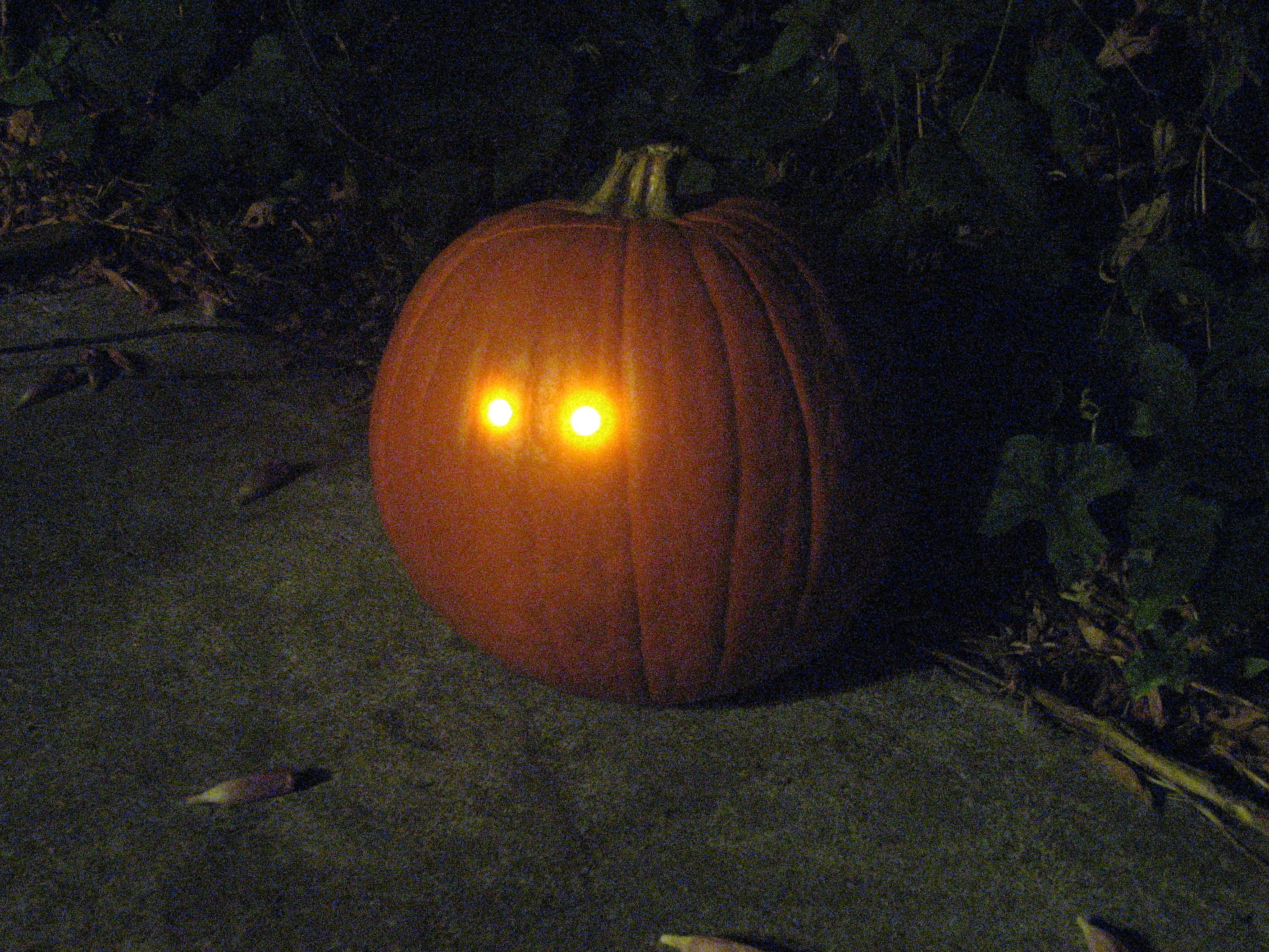
Here’s an inexpensive electronic circuit that you can build to put in your Jack-o’lantern. It provides power to drive a few LEDs at night, and automatically turns them off during the daytime. It’s a simple and automatic dark-detecting circuit that you can use to for your very own photosensitive pumpkin.
Our pumpkin project is closely related to the minimalist dark-detecting LED circuit that we showed previously.
In that project– basically an LED throwie with a sensor– a phototransistor controls a single LED.
While the minimalist circuit is marvelously compact and simple, it is limited both in terms of sensitivity, LED driving capability, and extensibility. It can drive a single red or yellow LED from a lithium coin cell– but that’s it– and it requires fairly bright light (e.g., direct sunlight) to turn off the LED.
So our new dark-detecting circuit is only almost as compact or simple, but is much more sensitive, and is capable of driving several bright LEDs for your Jack-o’lantern. We’ll get started with the basic circuit construction, using two LEDs for eyes, and then look at how to modify the circuit to use more or different types of LEDs.
Here’s a list of parts for the basic design (with two LEDs):
- A phototransistor (we use type LTR-3208E)
- 2N3904 (or similar) transistor, QTY 2.
- 5k ohm resistor
- Yellow or red LEDs, QTY 2. (We used 10 mm diffused yellow LEDs)
- 50 ohm resistors (one for each LED)
- Battery holder with 2 AA-size alkaline batteries

[Technical description of the circuit:
The photosensitive element is a phototransistor. We use type LTR-3208E here; it’s an infrared-sensitive type with a dark lens. Being IR sensitive it sees sunlight and incandescent lights, but not fluorescent or (most) discharge lamps– it really will come on at night. The typical “saturation” current of this type of phototransistor is only of order 1 mA, which means that under conditions much less bright than sunlight, we get much less than 1 mA of output current. To increase the sensitivity of our pumpkin enough to detect indirect daylight lighting– not just direct sunlight– we use the phototransistor as one element of a Darlington pair. When daylight is detected, the phototransistor turns on (just a little bit), which turns on the first 2N3904, which pulls the base of the second 2N3904 to ground, and preventing the LEDs from turning on. When it’s dark out, no current can flow through the phototransistor or the first 2N3904, which allows the base of the second 2N3904 to be pulled high through the 5 k transistor, which turns on the LEDs through that transistor. As drawn here, the circuit draws 0.5 – 1 mA (depending on ambient light) when it’s daytime and up to about 35 mA when driving the two LEDs at night. (If your LEDs are superbright types, you might want to cut down on brightness and power usage by using larger load resistors.) The photosensitive part of the circuit is independent of what’s actually driven by the second 2N3904, so you can change the load applied there easily. Our circuit is drawn with two LEDs, each with its own load resistor, however you can actually use 1-4 parallel LEDs if each has its own load resistor.]
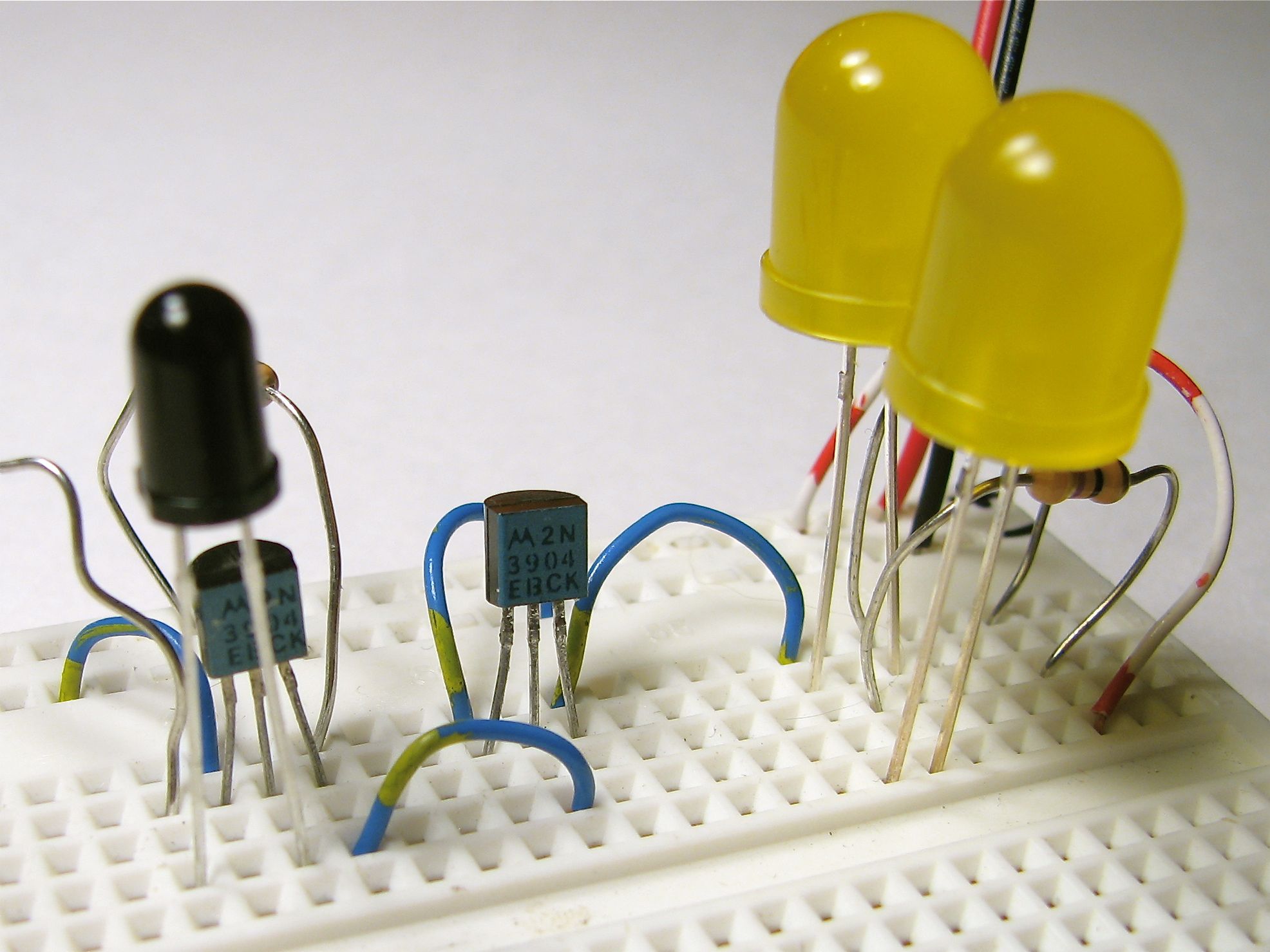
A good place to start playing with a circuit like this is on a solderless breadboard. For the most part you can follow the circuit diagram. You’ll need to know that on our type of phototransistor the flat side that denotes the “collector” pin (“C” on the diagram). Also, the pins of the 2N3904 are called (left-to-right) Emitter, Base, Collector (E, B, and C on the diagram), when viewing it from the front such that you can read the writing. On the LEDs, the side with the short lead and/or flatted faced on the lens is generally the cathode, which is the side with the flat bar in the diagram.
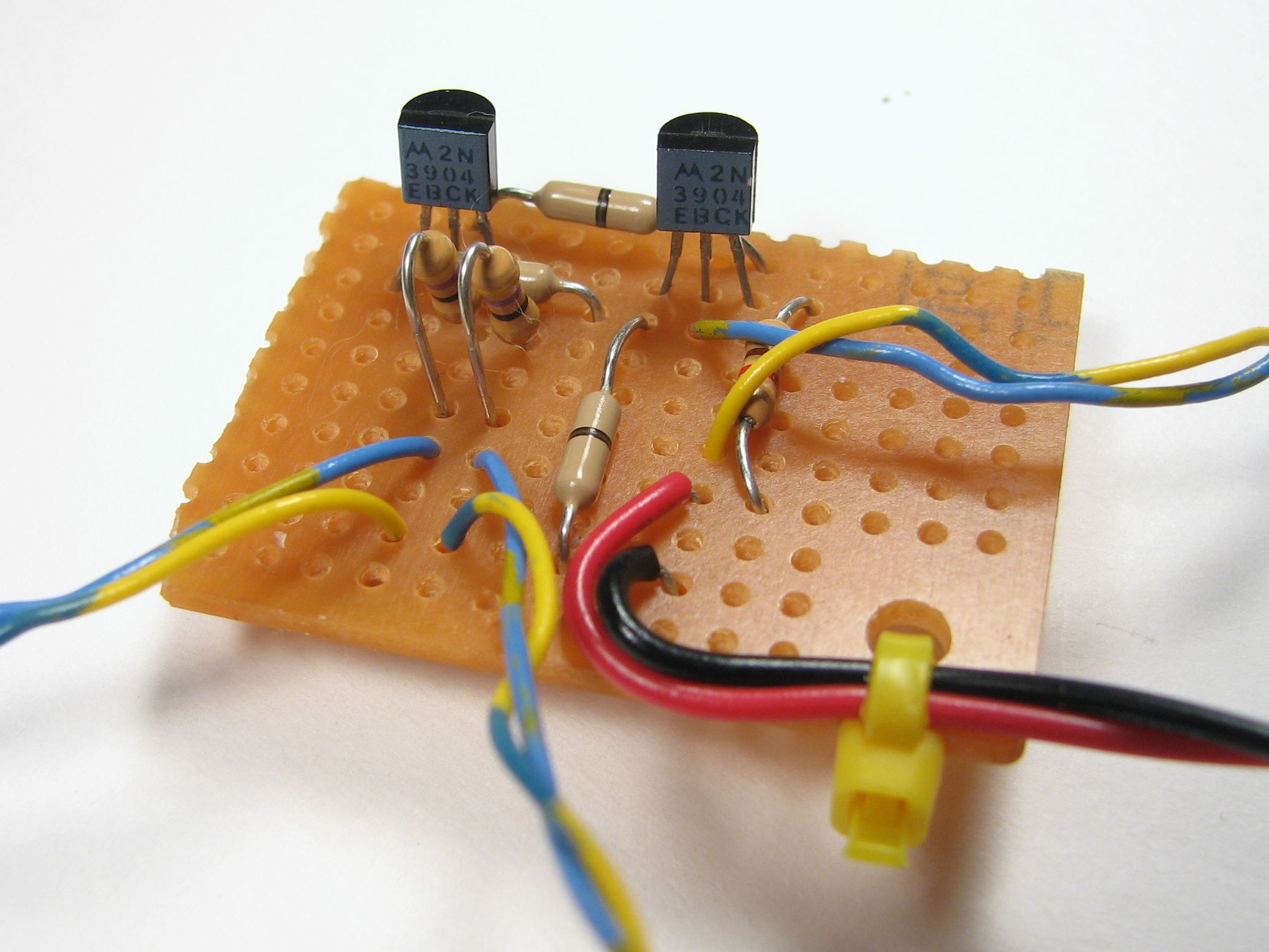
From there, we constructed the same circuit on a small piece of plain perfboard. There are three twisted wire pairs going off from this little board to (1) the photosensor and (2,3) the LEDs. (There are really just the two transistors and three resistors on the board– the resistor-looking thingies with one black stripe are just fancy wire jumpers.)
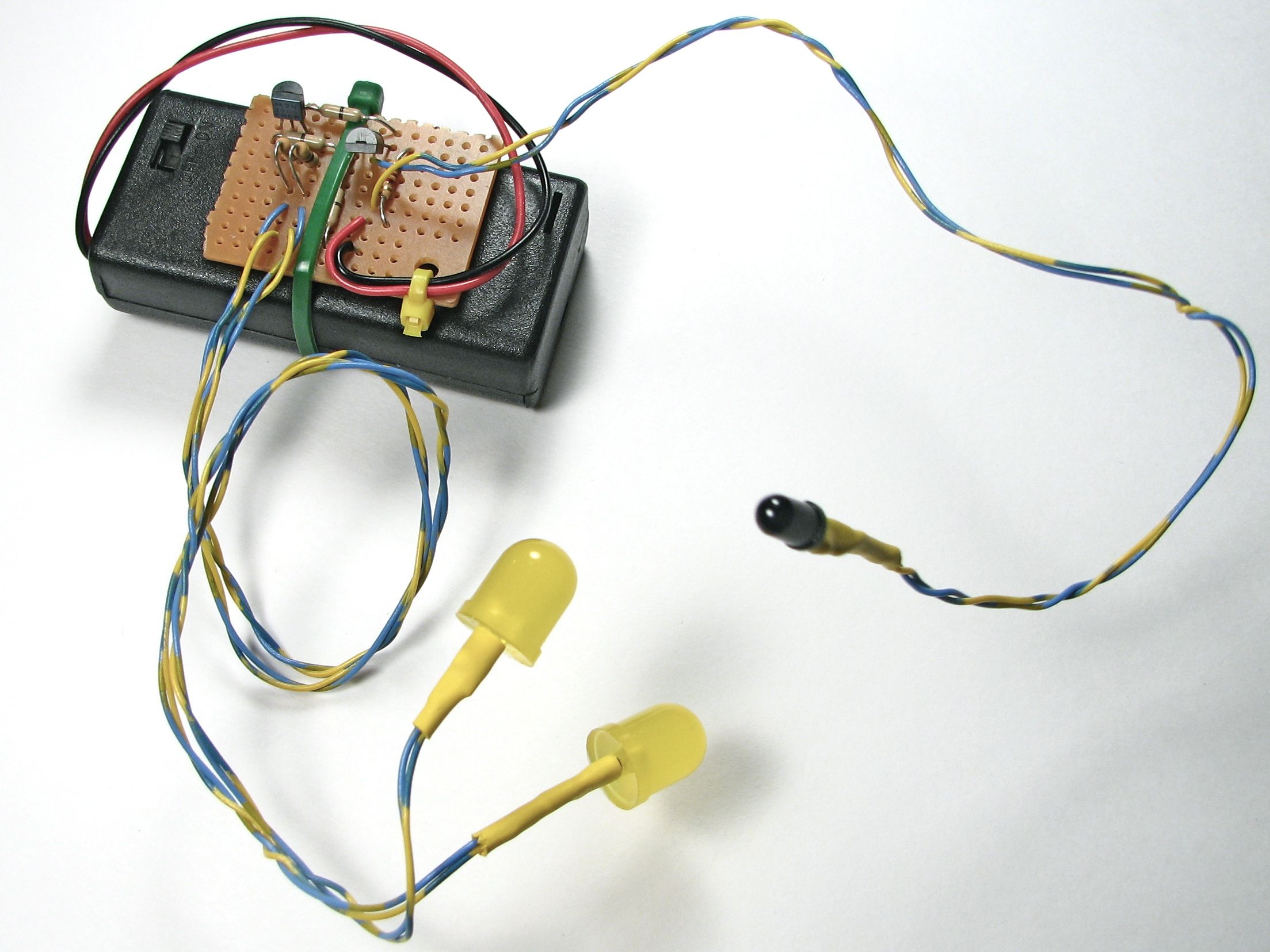
Here’s the whole setup with the phototransistor and LEDs visible at the ends of their wire leads. We use the long leads to be able to put the LEDs and sensor exactly where we want them in the pumpkin. We’ve protected the end of the leads with heat-shrink tubing. (No use shorting out our circuit with pumpkin goo.) The circuit board is strapped to the 2 x AA battery box with a cable tie.
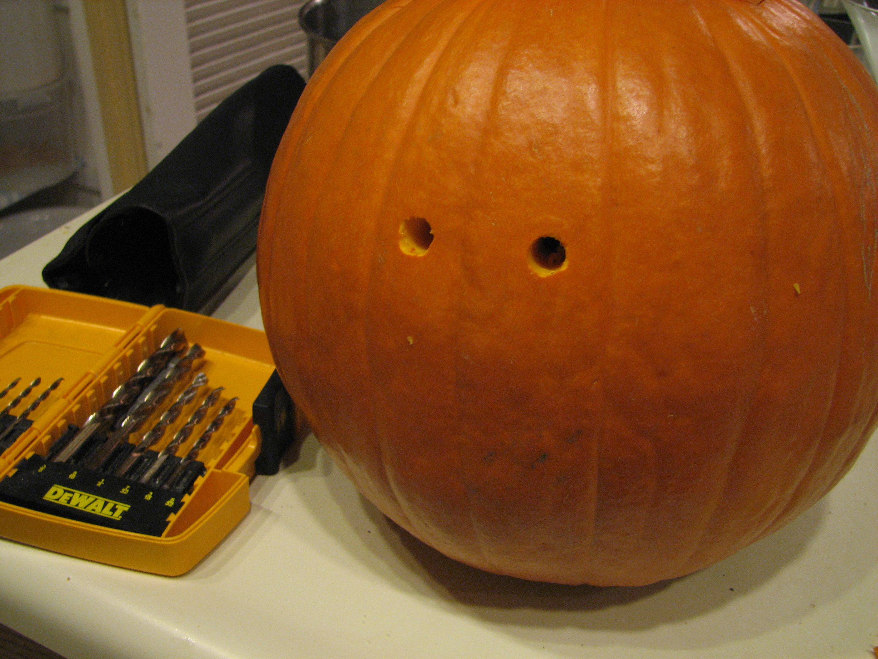
Our pumpkin design here is subtle– just a pumpkin with light up eyes, close together like some kind of small creature in the dark. But, you can go nuts in all kinds of ways with LEDs in jack-o’-lanterns, so please do! (And don’t forget to add your pictures to the Evil Mad Science Auxiliary on flickr!) Regular twist drills, turned by hand, work very well for making LED holes in pumpkins.
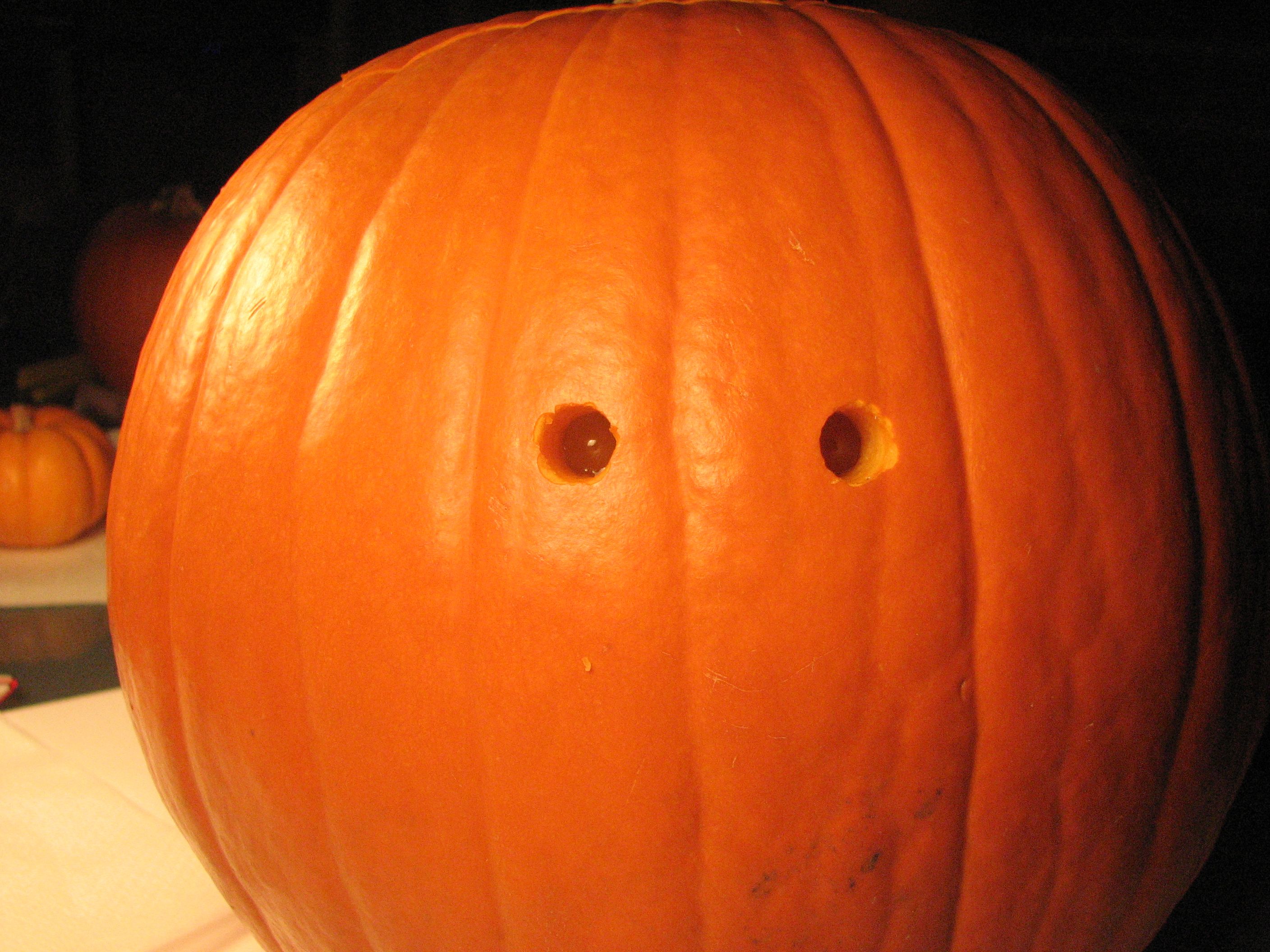
Here are the LEDs inserted into the holes. They’re nearly invisible. Note that the LEDs are off, because the room lights are on.
Next, to drill a hole for the phototransistor. We put this hole in the back side of the lid of the pumpkin, behind the stem.
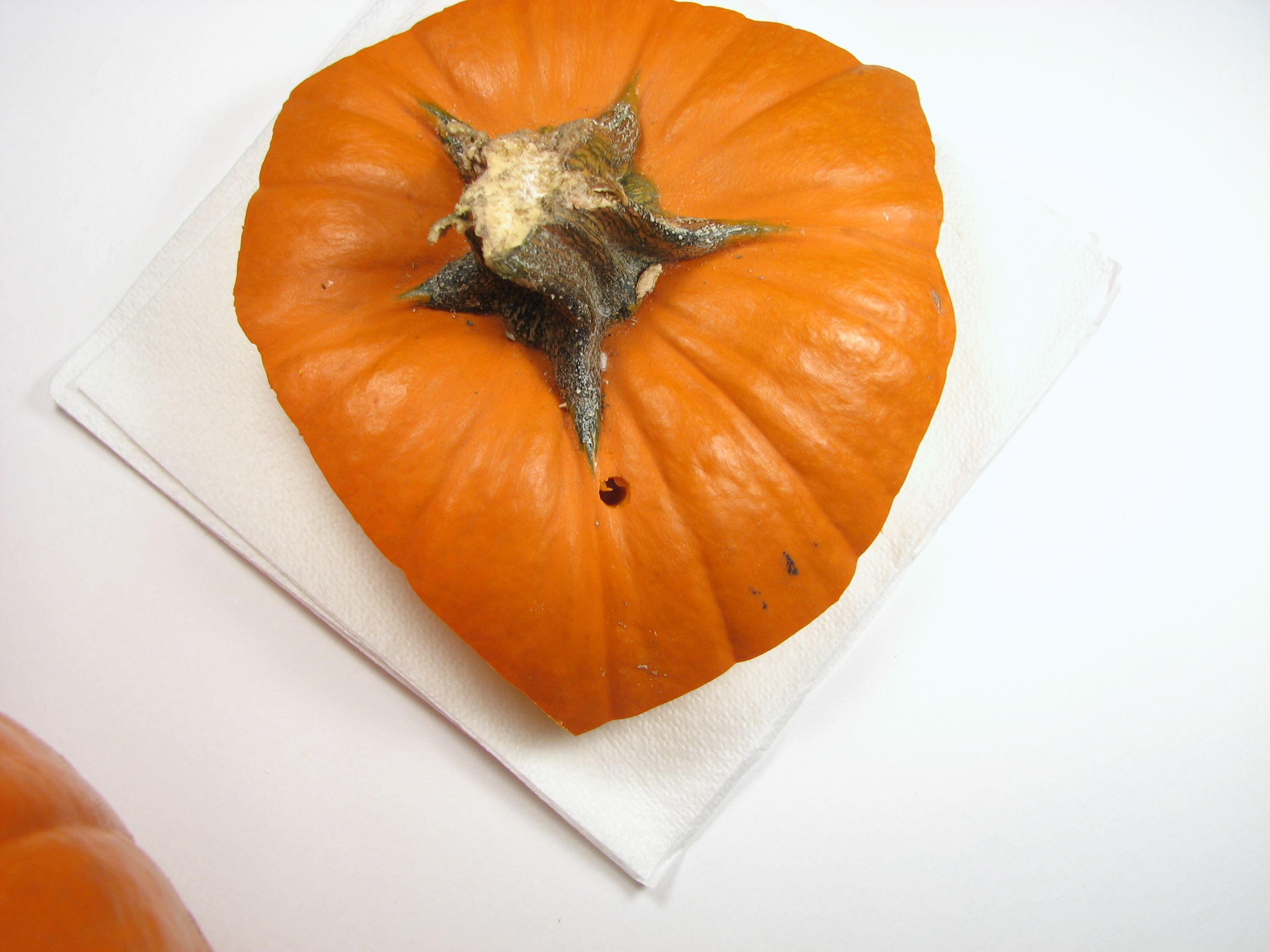
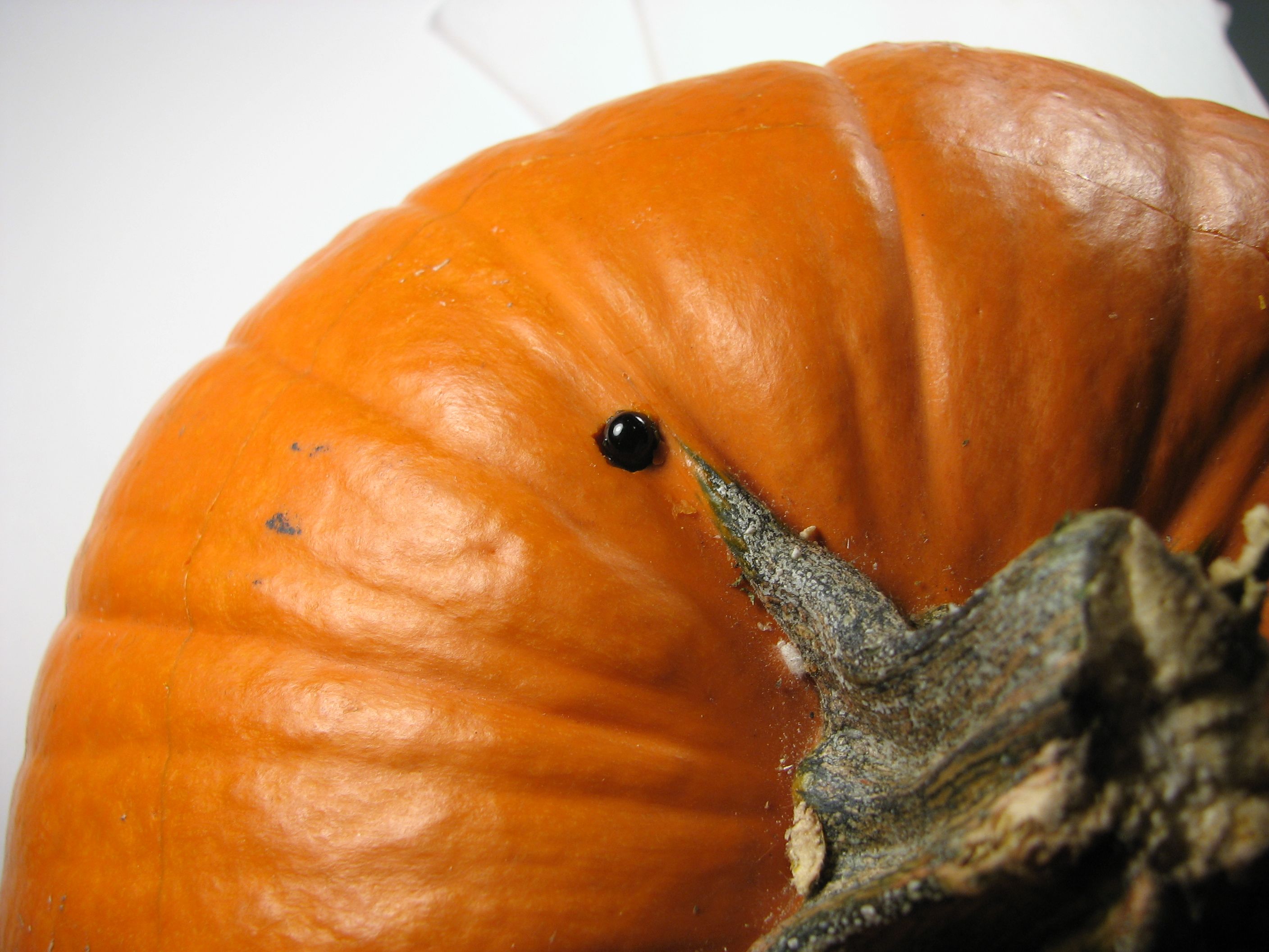
And here is the photosensor installed neatly in place. (You won’t notice it unless you look for it.)


You can test the pumpkin for photosensitivity by covering up the sensor by hand.
As we hinted earlier, this circuit is extensible– you can use it as the starting point for other things as well. You can add extra LEDs (each with its own load resistor) in parallel with the two shown in the diagram to use a total of about 35 mA. If you require slightly more output current, you can somewhat decrease the value of the 5k resistor, which will increase the base current through the second 2N3904, and produce a higher output current. (Note that this will make the circuit both more power hungry and a little bit less efficient.)
The circuit as drawn is fairly flexible in terms of input voltage, up to about 5 V, if you also increase the value of the LED load resistors to keep the LED current at a safe level. One consequence of this is that you could drive the circuit from 3-4 cells of rechargeable NiMH/NiCd battery or 4.5 V (from 3 AA’s) to provide a large enough voltage to directly drive green, white, or blue LEDs. Another approach to driving drive green, white, or blue LEDs is to leave the voltages where they are, but to use a joule thief, and hook that up where an LED would normally go.
Finally, here is a slight variation on the design:

This variation allows you to tune the light-sensitivity of the circuit. In this, we’ve replaced the 5 k fixed resistor with a 5 k potentiometer, and added a 1k resistor to restrict the maximum current into the second 2N3904.
You can find more pumpkin projects in our Halloween Project Archive.
I ordered the parts from DigiKey, we’ll see how it works out!
If I wanted to drive a bunch of LED’s (say a dozen, so I can make a mouth to go with the eyes), I presume I can duplicate that last transistor in the chain a couple of times… no?
Maybe you could make a Darlington pair with the 2N3904 and a larger transistor.
It’s worth a try.
—
Windell H. Oskay
drwho(at)evilmadscientist.com
http://www.evilmadscientist.com/
Actually, I have an 8-port darlington chip around somewhere, I’m sure that would work fine. Use the output of the last transistor to trigger all eight ports of the darlington (should take very little current) and use each port to power a couple of LEDs.
Have to make those D-cells, probably, but that’s a detail…
You will be limited by the fact that there’s a small amount of base current to drive the additional transistors, so that probably won’t work too well. I’d suggest reducing the value of the 5k resistor to (maybe) 1 k or so to allow additional current to be driven by the second 2N3904. A second approach that may work well is to use the output of this circuit to drive a small DC solids-state relay, for example an AQV101, which could drive a great many LEDs.
—
Windell H. Oskay
drwho(at)evilmadscientist.com
http://www.evilmadscientist.com/
Or perhaps a triode as seen in those lovely cardboard boxes a few posts back. Although you’d have to have a bit more in the way of a power supply, you’d have that nice, warm filament glow to supplement the that of the LEDs.
I would love to try making this! But I do have to admit, you did have me confused with the resistor diagrams. Over here in the UK we draw them as a rectangle.
The "squiggle" drawing is still fairly common in the US and Japan, while the rectangle is the standard in Europe. (Google search for "resistor symbol" for more information.) But in any case, each still has two terminals– you can hardly screw it up. :)
—
Windell H. Oskay
drwho(at)evilmadscientist.com
http://www.evilmadscientist.com/
Not always. Resistor as an actual is rectangle, as a load is zig zag?. From what I remember
Zig-zag is used only sometimes for certain resistive loads such as heating elements. In other cases rectangle is used.
Just a thought, is a pumpkin acidic enough to be able to eliminate the coin battery altogether, like a lemon battery?
If not, would an actual lemon thrown inside the pumpkin do it?
No. You seem to have a misconception about what a lemon (or pumpkin) battery is capable of.
A single-lemon battery produces about 2 mA at 1 V. To produce 35 mA at 3 V to run this project, we’d need three lemons in series, seventeen times in parallel– 51 lemons total. And (punchline) *they wouldn’t fit in the pumpkin!* And, when lemons cost $1 each at the store, we’re talking about adding $50 to the cost of this (otherwise cheap) project.
—
Windell H. Oskay
drwho(at)evilmadscientist.com
http://www.evilmadscientist.com/
FOR US READERS IN THE U.K, COULD YOU PLEASE GIVE A LIST OF SUITABLE COMPONENTS FROM THIS SUPPLIER:
<A HREF="http://uk.rs-online.com/">Radio Shack UK</A>
THANKS ALLOT :)
It would be awesome to throw up a quick digikey parts list for this project! It’s rather time consuming to hunt down the parts in online catalogs!
LTR-3208E: 160-1031-ND
2N3904: 2N3904FS-ND
50 ohm resistor: 49.9XBK-ND
5k resistor: 4.99KXBK-ND
Battery holder: SBH-321AS-ND
LED: no exact match.
Okay, that took me about four minutes. It’s not quite what I’d call "rather time consuming."
—
Windell H. Oskay
drwho(at)evilmadscientist.com
http://www.evilmadscientist.com/
That’s 4 minutes * 2 billion people who read this. That’s years, dude.
If you switch our the resistors leading to the LEDs could you up the voltage 12 and run more LEDs in series? For instance, 2 sets of three 20ma 5mm LEDs with a 90-100 ohm resistor before each series of LEDs.
Think my brain just popped – trying to make this circuit run off a 12v power source, used a 22k resistor in place of the the 5k and 470 ohm resistors for each of the 4 15000mcd blue LEDs. When I hook up the power, the LEDs light up, but with no affect from the phototransistor. I have tried running this circuit using different phototransistors ranging from CdS photoresistor "radioshack" to a mal100a "30v 50mA to -18L". Do you think it might be the phototransistor or my attempt at running this off 12v? Really wanting to run this off the 12v if possible. In addition I have many of the mal110a phototransistors. Figuring out which is collector and emitter was fairly simple for these. And, all of the phototransistors behaved the same when used outside of this circuit. If I run the led with its resistor and phototransistor – hooked up to power the led is dim, when its brought to a light source the led brightens. Yep, brain is gonna pop
I have a similar problem !!-
The project works well indoors–the LEDs go out (dark) when the lights are swithed on, and turn on (bright) when the lights are off, and when I take the project outside in the shade–the LED’s shut down (dark) –but in bright sunlight, the LEDs light up again !!
I thought it was the Phototransistor–so I replaced it with the clear one from Radioshack, and changed my transistors–and redid the wiring, to see if there was a short. No help! The LEDs contiue to turn on (light yes) in bright sunlight.
Hmmm.
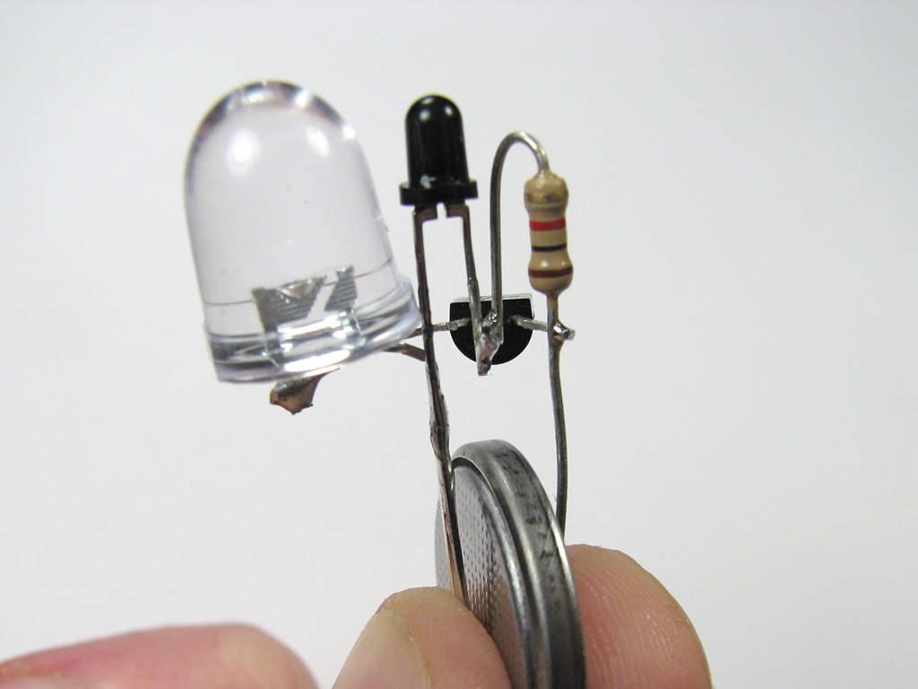
This picture looks like a tiny robot alien carrying a death ray :D
First off i am no expert with electronics. I have had training in the past buy have not used my knowledge in some years. I would like to make the small Cylon pumpkin, and incorporate the dark detecting circuit along with a solar panel to charge this.
Would i have to just use your Cylon circuit and add the solar panel and IN914 Diode and the LTR-3208E before the Cylon circuit? Any help would be appreciated.
Thad Johnson
thad.johnson@gmail.com
Or (shudder) a probe.
I made two of these just the other day and they seem to work well. Under normal desk light they light up. I had to stick it in front of a light bulb for it to shut off. Hopefully it will be good under daylight settings like in the photo’s above. Going to use it for the LED ghosts if possible.
Mind the soldering skills :).
http://tinkerdad.blogspot.com
Well done!!
Hi I’d like to do this project but I have not been able to find the phototransistor LTR-3208E locally. I have been offered a 5M3B phototransistor. Are the 2 similar and can be interchanged for this or similar projects? Thanks for your help and for a great site!
No idea. Can you post a link to the datasheet?
Windell H. Oskay
drwho(at)evilmadscientist.com
http://www.evilmadscientist.com/
Hi I bought this Phototransistor – datasheet here http://www.delta-electronic.com/Design/Data%20Sheet/tops050tb2.pdf but I have not been able to make the circuit work. Is there such a big difference between the two. Thanks for your help
Hi Windell, I’m a real newbie to all this so am not sure if this link http://www.elecmap.com/product-Diodes/15816/CL-5M3B-5mm-Photo-transistor.html is what you have asked for> I hope you will be able to help me now. Thanks