


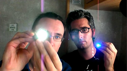
In this week’s Weekend Projects video podcast, Make Magazine’s Bre Pettis and I show you how to make a Joule Thief. The PDF file that goes with the podcast is here (450 kB PDF file).
So whatsa Joule Thief? It’s a little wisp of a circuit that allows you to drive a blue or white LED from a low voltage. Normally, if you want to light up a blue or white LED you need to provide it with 3 – 3.5 V, like from a 3 V lithium coin cell. But a 1.5 V battery like a AA cell simply will not work. But using the Joule Thief, it works like a charm. Not only does it work with a brand new battery, but it works until the battery is nearly dead– down to 0.3 V. That’s well below the point where your other toys will tell you the battery is dead, so it can steal every last joule of energy from the battery (hence the name). To learn how to make one, watch the video, which is available in a variety of formats.
The original site where we learned about the Joule thief shows you how to make a miniature version of this circuit, such that you can fit it in a tiny flashlight. However, in the video we show you how to make it big, large enough (1) to make with clumsy hands and (2) that you can see what we’re doing.
After the jump, some detailed photos of how the coil is wound in case you need more detail than in the video.
It’s a little hard to see through my fingers in the video, so here’s the detailed view of the coil and winding your own.
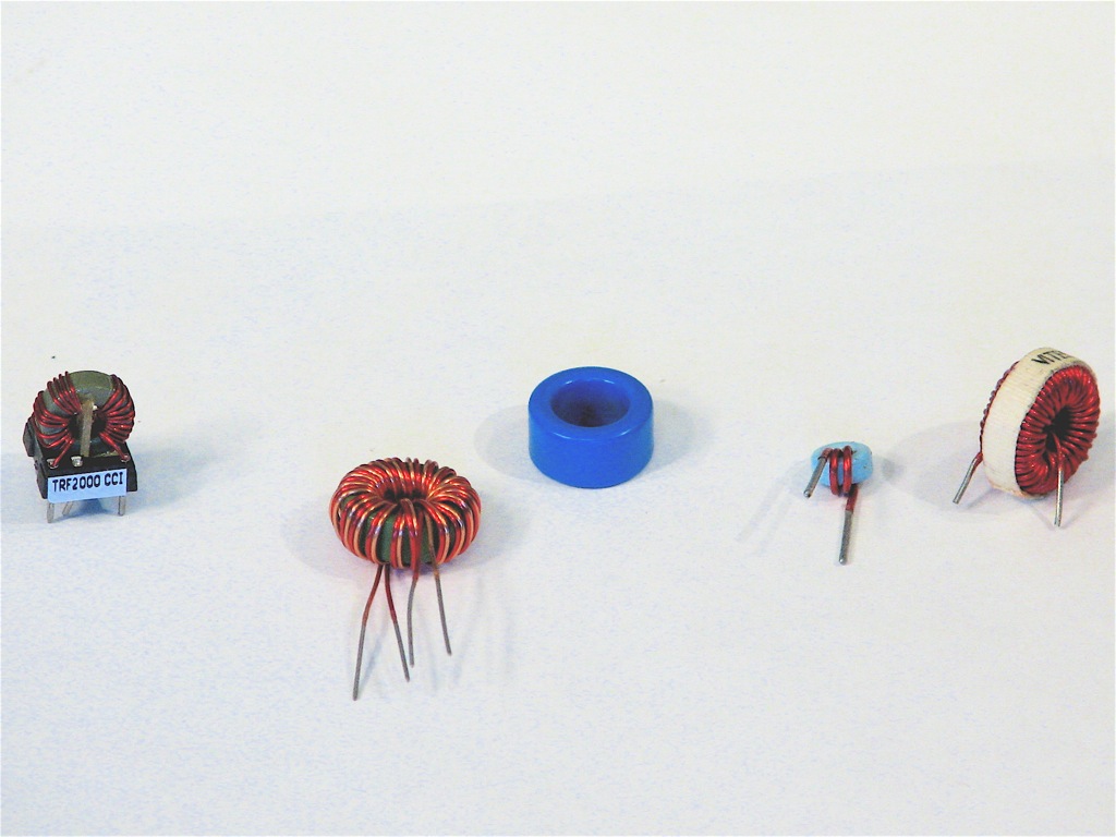
First, here is a selection of ferrite toroids, inductors, and transformers that are suitable for using to make a Joule Thief.
Depending on the type that you start with, you may be able to use the existing wires or need to take them off and wind it yourself.
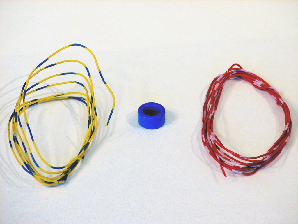
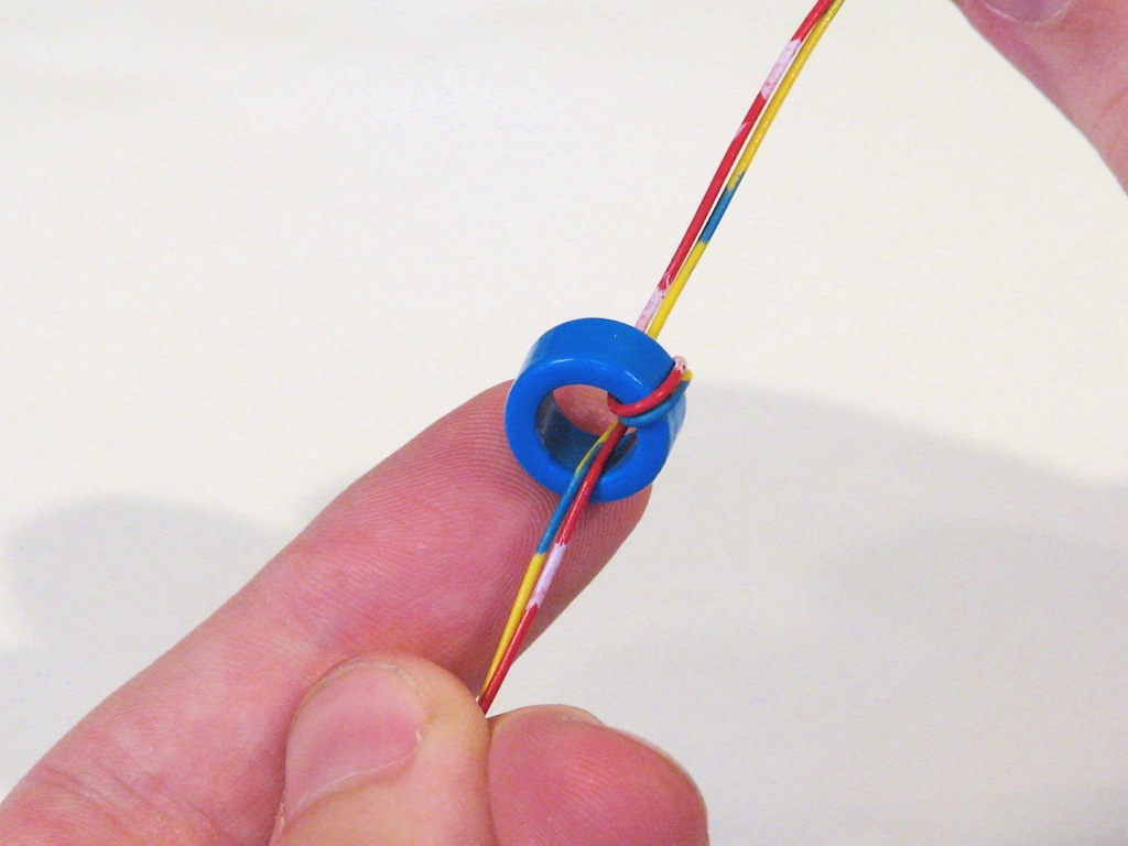
To wind your own coil, start with two colors of insulated wire and a bare ferrite toroid.
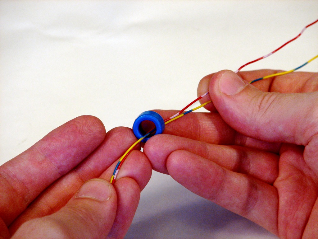
Take the two strands of wire through the center of the toroid.
Keeping the two strands together, wrap them around and through the toroid again.
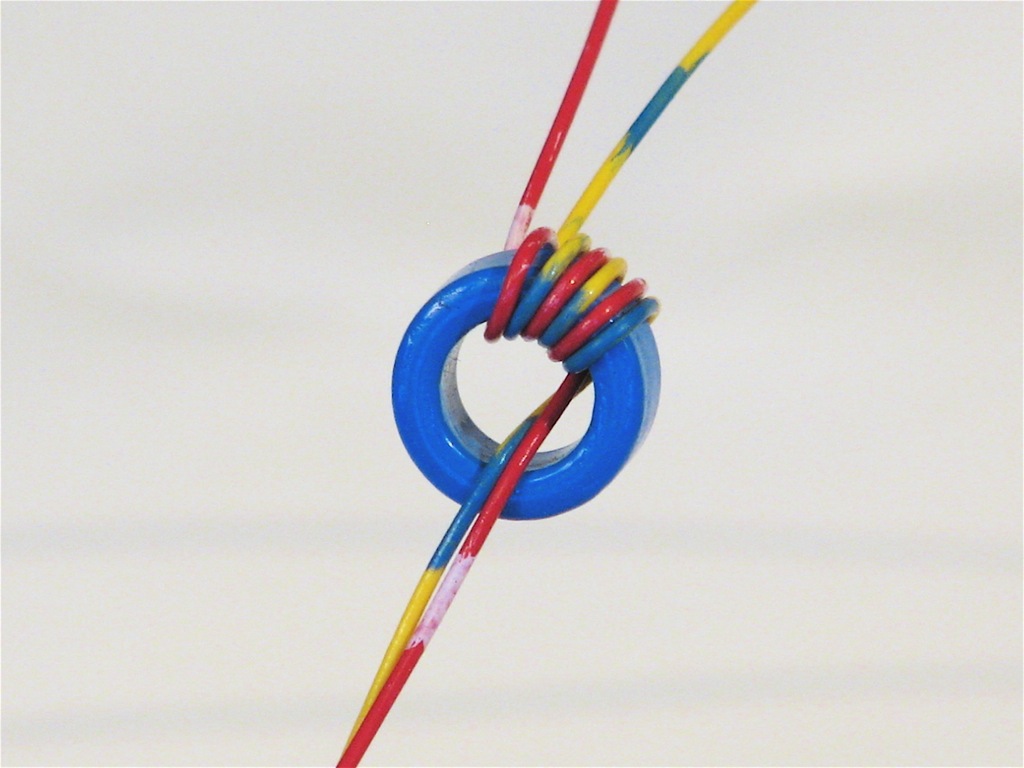
Keeping the two wires together, make a few more turns through the center.
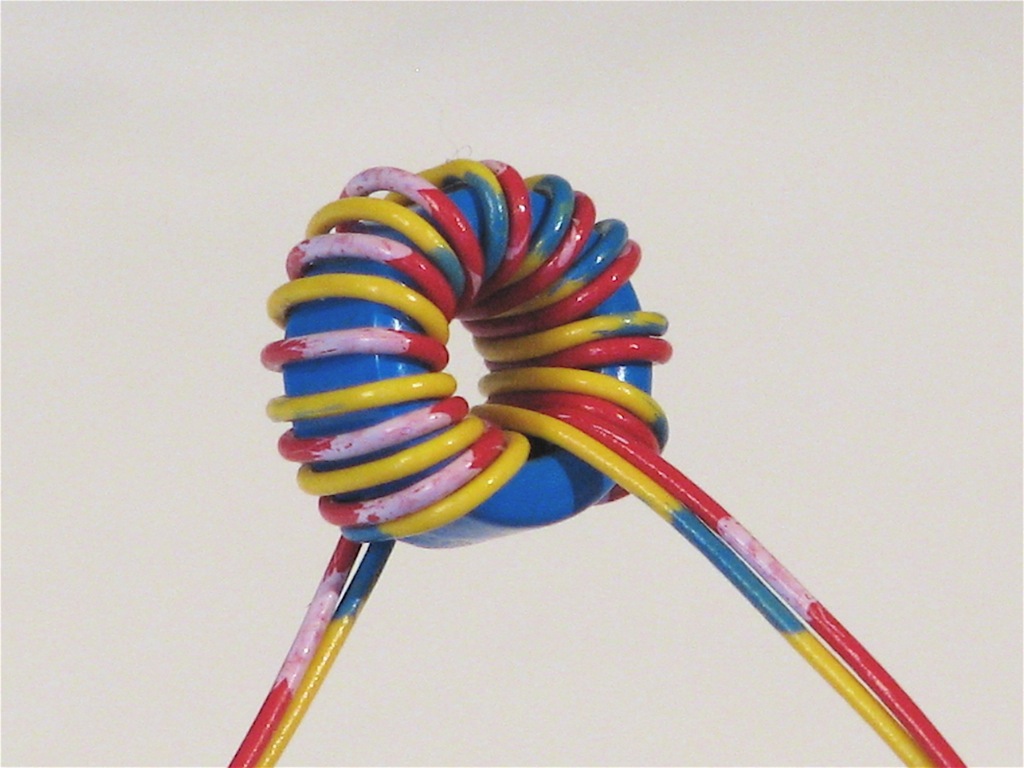
Keep winding until you fit as many turns as will fit in a single layer around the toroid, typically 7-10 turns with thin insulated wire.
Clip the wire leads down. Note that we have two pairs of wires: one coming out the front, and one coming out the back.
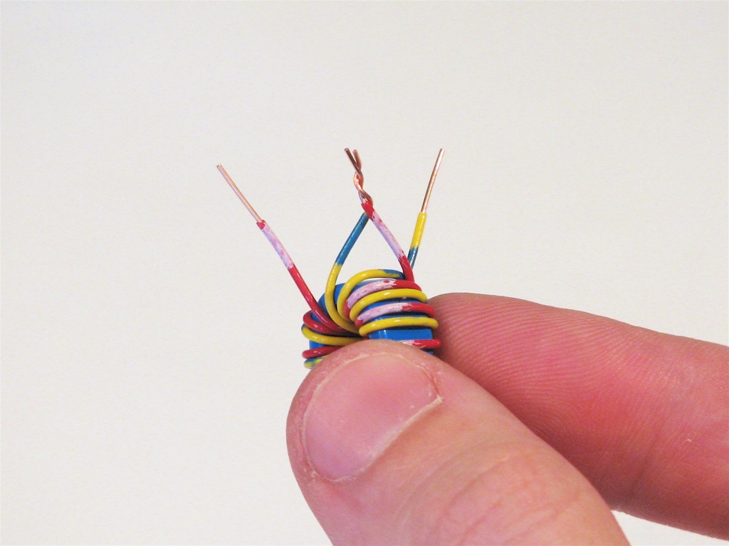
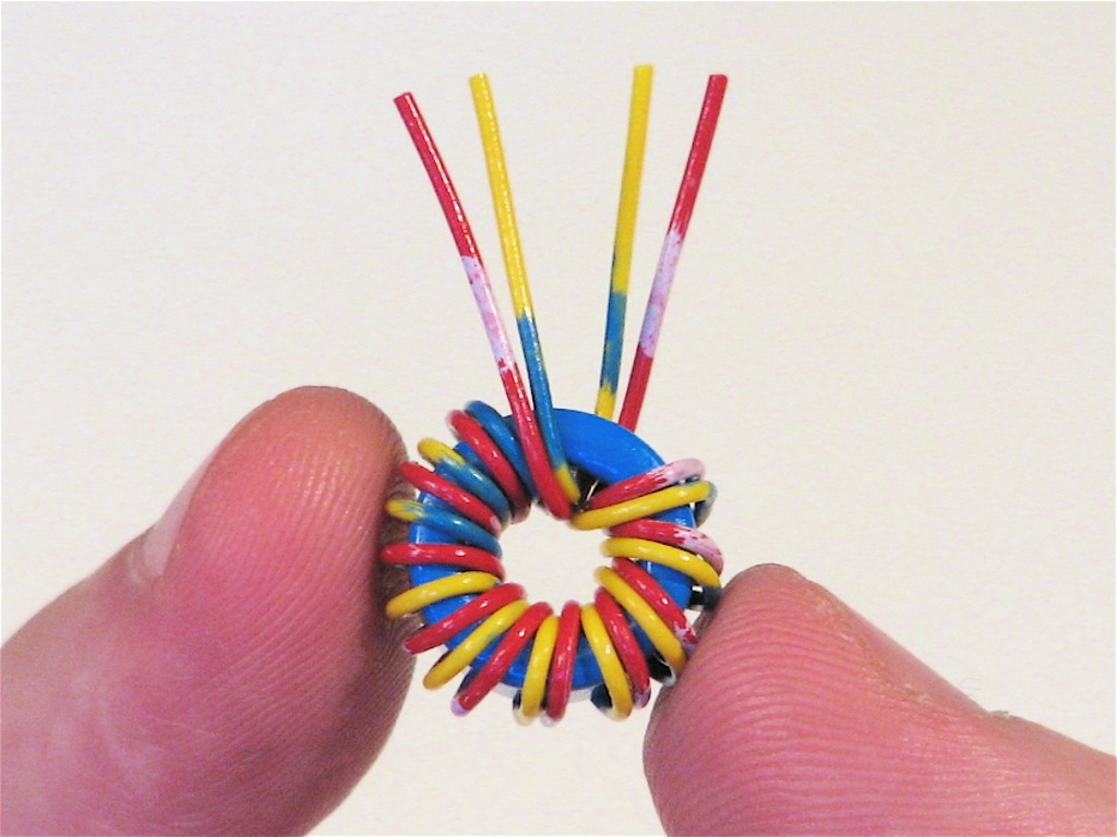
Strip the wire ends. Take one wire from each pair of different color and attach them together.
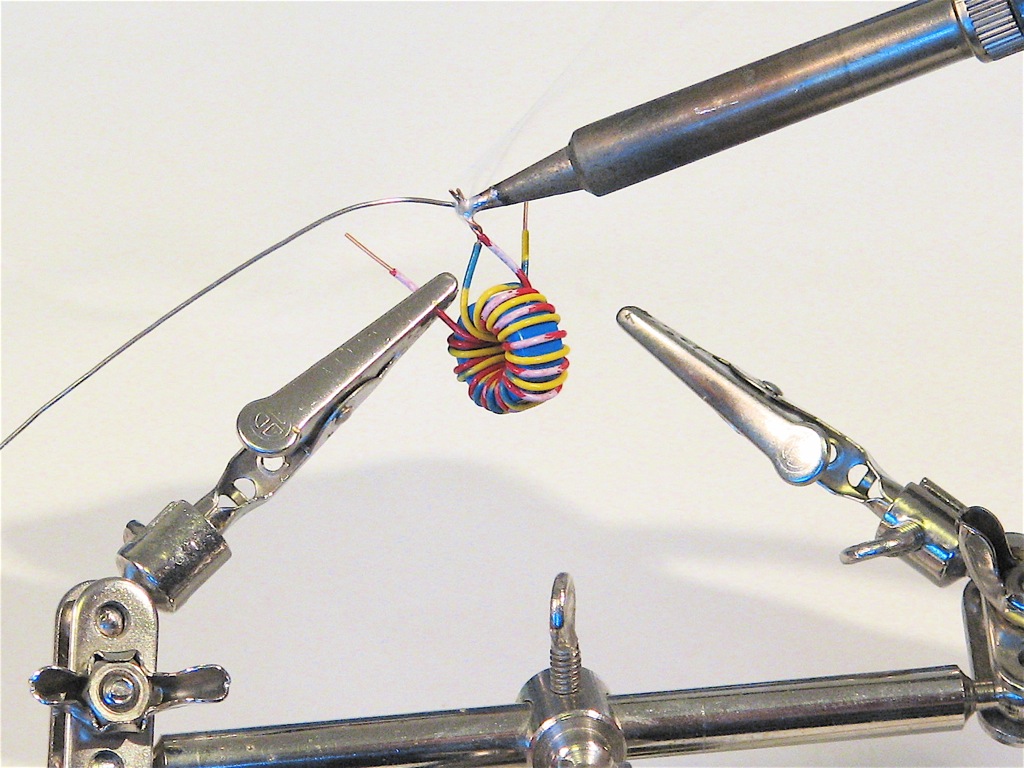
Solder the cross-over pair together. This is the “common” point of the coil windings.
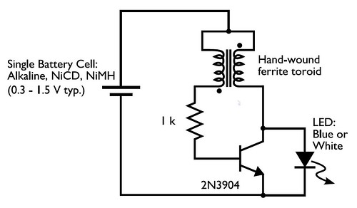
In the circuit diagram for the Joule Thief, the common point of the toroid is the connection at the top of the hand-wound ferrite toroid, in the upper right of the diagram. This goes to the positive end of the battery. The other two wires from the toroid go to the resistor and to the intersection of the transistor with the LED.
One other detail that you may need to know is the symbol and pinout of the 2N3904 transistor. In the symbol, the part with the arrow is the “emitter”, the “collector” is the end above it, that also connects to the LED, and the “base” is the wire leading off to the left, between the collector and emitter. (Also remember that the end of the LED with the flat side and short lead is the end that has the flat bar in the diagram.)
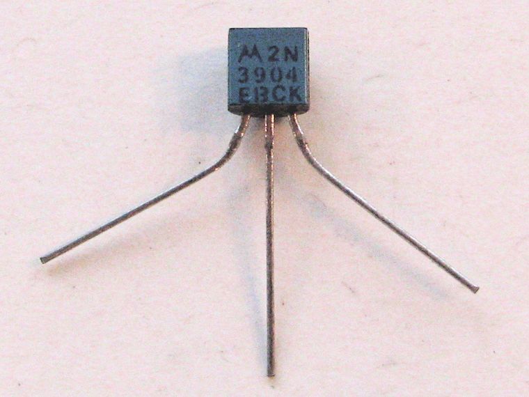
An actual 2N3904 transistor looks like this.
(Well, like this if you’re hungry.)
The pins, holding it so that you can read the text on the flat side are (left to right) Emitter, Base, and Collector. I particularly like this one because it has that little EBC legend on the bottom.
So how does it work?
Pretty well, actually. (The technical discussion has been removed.)
As a side note, this is not the most efficient circuit around; its beauty is that it works with such a low voltage. So, this is a great circuit to use with a dead or dying battery, and less so for use with a brand new battery.
Nice job on the podcasts. I’ve been watching Weekend Projects since it started, and this is the second time it has overlapped with some other project I follow. Though this time it’s a double, since it’s you and a circuit from Big Clive’s site.
It’s a neat little circuit, and I’m glad to see it get more publicity. I just hope it doesn’t prompt anyone into electrocuting themselves with any of the homer high energy projects of his.
I saw one of your projects in Popular Science as well, congratulations there.
This project is awesome!! I’ve already found a couple of uses for it, and even found variations of smaller (but still fully functional) inductors!! The capacity of this circuit is amazing aswell! I’ve had a record 6 (six) 3v LEDs working at once with one 1.5V battery! Not bad for $0.79 and an old power supply!
Cool, I made one :) Something is weird about it though. My Joule Thief makes a soft, very high-pitched noise whenever it is on. Has anyone else noticed that before, and could there be any reason for it? Thanks for the explanation on how it works!
The normal range of hearing is up to 20 kHz, in young folks at least. My joule thieves oscillate at about 40 kHz, well outside the range of normal hearing. Since you can hear yours, one of three things is the case. (1) You are not a human. You have super-hearing. You may be a bat, for example, or perhaps a superhero. (2) Your Joule Thief circuit, for whatever reason– (choice of toroid?) oscillates at a much lower frequency so that you can hear it. (3) A nonlinearity in the circuit is producing a vibration at half the oscillation frequency, near the upper end of your hearing range.
What to do about it? Adding a capacitor, as is done in some of the versions of the Joule Thief, may cut down on the noise for you. You may also try using a different toroid.
—
Windell H. Oskay
drwho(at)evilmadscientist.com
http://www.evilmadscientist.com/
Simply tighten the windings on the toroid, or use glue immobilize them. Loose windings will oscillate, like in a motor or a dynamic loudspeaker.
Didn’t they teach you at school about wires and magnetic fields?
The noise is perfectly understandable. It’s basically an oscillator. The frequency is determined by the stray capacitance value in association with the inductor. It may run at a audible frequency, or it may run at an ultrasonic frequency, depending upon the value of stray capacitance. Now, since it is oscillating, if everything isn’t tied down extremely well, you may get some vibration from some of the components (e.g., the wire in the inductor), and this vibration will be turned into sound. Or, for that matter, even the iron or ferrite core of an inductor can change shape when the magnetic field through it changes:
http://en.wikipedia.org/wiki/Magnetostriction
Dave
Try using enameled wire and/or a coated toroid. With 7 turns on my toroid using a 2N222 transistor I a measuring 65kHz. This freq. is way above audible range unless your a bat.
Mike
This reminds me of being able to hear a flyback transformer in aTV/Monitor (CRT). I could hear when my algebra teacher and general mentor in high school would shutdown the computer and leave the monitor on. Also can hear a TV with a CRT that is muted. Not always, but many times.
It’s usually a loose transformer, or so I am told.
I can hear those too– simply drive me nuts because no one else is bothered by it. The noise generally comes from the transformer itself, not from the whole transformer moving around.
—
Windell H. Oskay
drwho(at)evilmadscientist.com
http://www.evilmadscientist.com/
Technically, rather than a "loose transformer", it’s actually loose wires on the transformer. In my (late 70’s) TV repairing days, I would sometimes see flyback (high-voltage) transformers with wedges driven in under the epoxy coating, to tighten up the windings and keep the noise down.
The earlier remark about magnetostriction applies here to, the core itself may expand and contract very slightly with changes in the magnetic field.
Yeah, what he said! ;)
—
Windell H. Oskay
drwho(at)evilmadscientist.com
http://www.evilmadscientist.com/
I have the same experience , my Physics teavher told me that was an an over charge problem , Well , what is happening is that the transistor is working faster than usual , You can tweak out the thief to avoid this sound , what i did was removing to turns of wire , no sound was emited again
Yes ! if I put 8 volts though my Joule thief – which has a power transistor – it sings and lights a compact florescent lamp
I assume this is because it is switching on and off at audio frequency
Interesting design. It vaguely reminds me of a LED flasher I built with a UniJunction Transistor (UJT) [1], and LED, and a 9 Volt battery.
[1] Does anyone else remember those?
Dave
I’m afraid that I’ve never even heard of them– but you can still get them online if you want to build another. Looks like an easy circuit.
—
Windell H. Oskay
drwho(at)evilmadscientist.com
http://www.evilmadscientist.com/
If anyone is intersted I captured a waveform accross the LED.
Output looked somewhat square at 2.48V amplitude but with overshoot it was 4.2V, 50% duty cycle @ 65.6kHz
I had 7 turns on my coil
Mike
Does anyone know what the final efficiency of these devices is? It’s a neat way of cranking voltage up but thermodynamics always gets in the way and you have to have heat and eddy current losses here.
The efficiency will depend on your toroid and its losses, but it is generally *not* one of the most efficient types of switchers. See some of the other links about Joule Thieves in the comments to the post at Make– someone actually measured it. There are also a few tricks that you can play to improve the efficiency. My take on this is that we use batteries that are already deemed *dead*, so any use that we get at all is a very good thing.
—
Windell H. Oskay
drwho(at)evilmadscientist.com
http://www.evilmadscientist.com/
What I would like to know is there a way to get more voltage out of it? Say I want to input 3v instead of 1.5 or 1.2v. I have tried it with a 3v battery but it wont light/burn out the led.
I was thinking of trying to adapt this to power a pic micro at 5v from a 3v battery. Of course a capacitor would be needed to stabilize the output.
Can’t the PIC run at a lower voltage?
Anyway, you can put a cap across the output. To get a higher output voltage (and lower current, of course) you could increase the forward voltage by using two LEDs in series, rather than one.
—
Windell H. Oskay
drwho(at)evilmadscientist.com
http://www.evilmadscientist.com/
They can indeed but when your also powering things like an lcd that requires 5v it it just easier to run them both at 5v.
The project I am working on now I have to have 4 AA batteries for 6v and then us an lm3905 regulator to drop that down to 5v.
What would be nice is to find a way to make a regulator that will up the voltage if the input is under what is required (step up) and if it is over the required voltage then it will step it down. Preferably a switching type step down as they are more efficient than linear regulators like the 3905.
Take a look at a DC/DC switching converter, perhaps something like a Maxim MAX751CPA chip:
http://pdfserv.maxim-ic.com/en/ds/MAX751.pdf
although there are LOTs of other DC/DC switching converters out there.
Dave
Well it does come as a dip package which is nice but it looks like it is only good for 150ma. Seems a little low to drive the pic micro, the lcd, and the lcd back light. I have some 500ma or 1A switching regulators that are pin for pin with the 3905.
I am trying to design this so it can take 4 normal AA batteries or 4 1.2v rechargeable batteries. Though my version is going to be powered with two li-ion batteries to bring the weight down.
It works great. Here’s a little video video of my cnc milling out a small circuit board for the Joule Thief.
Enjoy
Some of my blogs that deal with LED and 1.5V
http://watsonseblog.blogspot.com/2007/09/i-found-another-1.html
http://watsonseblog.blogspot.com/2007/08/i-was-perusing-quantsuffs-led-web-page.html
This website (in Japanese) uses the same circuit with a transistor that’s capable of driving the LED to very high current. So they used another transistor to regulate the current. If the battery voltage drops, the LED doesn’t lose brightness so fast.
http://watsonseblog.blogspot.com/2007/02/another-led-v-boost-circuit-in-japanese.html
http://watsonseblog.blogspot.com/2007/02/another-website-with-led-v-boost.html
See my blog for even mroe LED V boost ccircuits. watsonseblog.blogspot.com
i made something very cool with a joule thief i built here in my protoboard: i could get a LED to light-up out of 2 series connected homemade lemon-batteries! hahaha
they gave me about 2V in the series conection, although very high internal resistance
Nice!
—
Windell H. Oskay
drwho(at)evilmadscientist.com
http://www.evilmadscientist.com/
I made the Joule Thief and was ecstatic when it worked the first time. Being a high school student with hardly any electronics experience, I was very proud. I’m working on a project for a competition that requires an electric vehicle to move a specific distance between 5 and 10 meters, with the exact distance to be announced at the competition. I want to use the LEGO RCX so i could make a simple program to run the motors for a specific time depending on how many times i push a button. The only problem is that the competition limits the battery usage to 4 individual cells rated at 1.5 volts or less each, and the RCX runs with 6 AA batteries. I thought that that using the joule thief I could use 1 battery to generate 3volts to make up the difference, but it is being very finicky. I replaced the LED with a diode so i could use the Thief as a voltage source, but when i use my multimeter to measure the voltage, it steadily climbs to about 10V, but when i connect it to the RCX and turn it on, the voltage from the Thief drops to about a volt. I was wondering if there was a simple way to fix this. My resources are limited, i.e. Radioshack and scavenged parts from old electronics. Thanks for the great walkthrough! It was perfect!
-Nick
I admittedly do not know much about electronics. But it sounds like the joule theif is charging in a way, it gets filled up and then dumped out and can’t recover fast enough. Maybe you could use serveral joule theives and cut there recovery time? Maybe you could take out some parts of one of those induction fllashlights. However it works it seems to keep a steady flow of electricity to the LED once charged.
I made my first Joule Thief tonight … worked first (ok, uh, third) try. :)
Here are some things NOT to do:
1. Don’t accidentally cover a battery contact with melted plastic while trying to solder stuff.
2. A 1KOhm resistor is brown-black-red, not brown-black-orange. The circuit won’t work with a 10KOhm resistor, at least not for me. :)
But once I figured those out it worked first time! Made completely of components from the corner R*Shack, too. I know, I know – but convenience won out. The only ferrite cores they had were some pre-made choke coils – I clipped their wires off and wrapped mine on. Easy!
I’ll use it as a night-light for now. I’m curious to see how long it lasts on "dead" non-rechargeable Lithium AAs. I have a bunch of those that I use in my digital camera. For the camera they are expensive, but they last forEVER so it pays off. But I’ll bet there’s a lot of power left in them after they are "dead".
I see some variations online that use the Joule Thief as a solar trickle-charger for a rechargeable battery. I’m going to try that next. You replace the battery with a solar cell, and the LED with a battery. You have to add a diode so the battery doesn’t drain through the thief. Wonder if I can use this to keep an Evil Mad Scientist Business Card running 24/7 on solar power?
Thanks for all the fun, …Sam
Hmm, I didn’t expect this!
When I first got my Joule Thief running there wasn’t any visible flicker to the light, but now after running for 24 hours, it is flashing at about 8 Hz.
If I touch the base with my index finger and the collector with my thumb then it speeds right up again and the flashing becomes almost invisible. The rate of flashing speeds up slowly over a second or two; when I stop touching the base & collector it slows down again instantly.
Capacitance? Would a small cap across the base and collector fix this? Or ???
The transistors I’m using are of dubious vintage. Supposedly they are 2N2222, according to one page on the RadioShack site, but the package I bought carefully doesn’t say, so they could be anything.
Well, the fun continues! :)
That’s… odd. I’ve never seen one get slow. If adding capacitance (like your finger) makes it work better, then that’s apparently a solution, but it doesn’t explain what’s going on.
Are you sure that you’ve got your transistor with the correct polarity? 2N2222’s, for example have the emitter and collector reversed with respect to the pinout of the 2N3904 that we used….
—
Windell H. Oskay
drwho(at)evilmadscientist.com
http://www.evilmadscientist.com/
The plot thickens! Last night I made a second Joule Thief with the same R*Shack transistor as the first. This one’s on a breadboard so I can experiment with it to see what is going on. The only parts change from the first one is the LED – this one’s blue instead of white.
When I first made it this second one was lit solid (to the eye). The voltage on the battery was 1.4V.
Now, 24 hours later, the voltage is down to 0.6V, and the blue LED is blinking on and off with a period of 22 SECONDS. It pops on bright, then slowly fades for 15 sec, then is dark for 7, then pops on bright again.
The original Thief is still blinking at about 5-6 Hz, just as it was 24 hours ago.
It’s fascinating that everyone else reports oscillation rates in the KHz range and mine are many orders of magnitude slower!
Here’s another variable. I made my coils with very thin wire – 30 gauge "insulated wrapping wire". I get 15 wraps on my 3/4 inch diameter ferrites.
I picked up a bunch of 2N3904s and a whole bunch of identical white LEDs from Jameco today and will see if they make any difference. Guess I’ll make 4 or 5 more this weekend, varying a few things (turns of wire, resistor values, etc) to see what happens. Magic!
…Sam
It was the transistors. Used the proper ones and all is well. :)
Very interesting– I wonder what it was about the that caused them to behave so strangely.
—
Windell H. Oskay
drwho(at)evilmadscientist.com
http://www.evilmadscientist.com/
your explanation is WRONG, at least some parts :P…..
when the transistor opens, a current on the RIGHT side of the transformer begins suddenly to RISE , which induces a counter-voltage on the LEFT side, so that the left side SHUTS DOWN…ok….so at that moment we have a large current on the right side which is shut of due to the left side….the current on the right side however opposes to die and induces a high voltage, which only then flashes the LED….
so basically the current on the right side in the solenoid inhabits a certain amount of energie E=I*L and when the current is forced to die this energy has to go somewhere very quickly…..
the resulting induced voltage doesnt depend on the current itself, but on the CHANGE of current per time, i.e. dI/dt, so switching off ANY kind of current basically leads to a induced voltage….a solenoid has a large "inductance", so switching its current off you get a flash….it’s the same with the ignition in a car…..you have a solenoid powered by the DC car battery and a switch which turns the solenoid on and OFF=sparkle :)
so instead of the transistor just use the right side of the torrenoid and a switch after the LED that you turn on and off with a 40kHz frequency :D :D :D
have fun :P
My description is quite correct; it just does not go into unnecessary detail. I can calculate current through an inductor as well as the next guy, but explicitly doing so in this case *does not* add clarity for the casual reader or experimenter.
> doesnt depend on the current itself, but on the CHANGE of current per time, i.e. dI/dt,
Yes, V=L dI/dt, which means that if we switch off the current in a fixed amount of time, then a larger current will result in a larger dI/dt. Which means that yes, the voltage *does actually depend* on the initial current. The equations don’t say that I’m wrong, they just add unnecessary detail.
>so instead of the transistor just use the right side of the torrenoid and a switch after the LED that you turn on and off with a 40kHz frequency
Yes, that’s how a regular switching boost regulator works. The beauty of this Joule Thief design is that you *do not need* a separate oscillator circuit. There are some circuits (also called Joule Thieves by some) that actually have a two-transistor oscillator circuit and a single inductor following it. I happen to like this design much better.
—
Windell H. Oskay
drwho(at)evilmadscientist.com
http://www.evilmadscientist.com/
Not completely on-topic and not completely off-topic, but I want to make some of these and I also have an old PSU from a PC that’s blown. I know for a fact there’s bits inside this thing that I can use, but The Internet has made me paranoid about opening it up and stripping them out in case I electrocute myself with any residual charge that might be lurking. What’s the safest way to take apart a PSU to salvage bits n bobs for joule thieves and their ilk?
Here’s a couple of ways to make sure you dont get a shock
1) Leave the PSU unplugged for a few days before opening the case just to be on the safe side.
2) Short out all of the capacitors you can find with an insulated screwdriver.
3) Get a small peice of tin foil and hold it with a non conductive material then scrape it along the non component side of the board
And if you really are that paranoid about electricity you could just wear rubber gloves.
i got my torid cores from an old psu there was no current in it but that may be because it was left in a shed for 2 years. but just short the leads of the cappacitors together with a insulated screwdriver and it should be ok just check with your multimeter first
Looking for a source of free or cheap small gauge insulated wire in many colors ?
Old parallel printer cables ! Especially non-IEEE 1284 Cables.
Fine insulated wires great for wrapping tiny toroids, perfect for Joule Thieves !
Free from your junk box or cheap at thrift stores. I’ve never paid more than a dollar for a cable
of any kind at thrift stores.
IEEE 1284 cables give you the added bonus of braided shield to stash in your goodies.
Get out there and build something !
Estwald.
Hi, I’m new to transistors and I have a bunch of questions:
1. If I wanted an LED with different specs, can I just add a resistor before the LED in series, treating the rest of the circuit like a 3V battery?
2. What would happen if I added multiple batteries at once? Would the voltage be too high, and short out the LED?
3. What if I had x number of batteries, and used x number of LED’s in series? Shouldn’t this give me the same effect as I would normally have, but with multiple LED’s illuminated?
4. What if I used one battery, but put LED’s in parallel? Would this just draw more current?
>1. If I wanted an LED with different specs, can I just add a resistor before the LED in series,
>treating the rest of the circuit like a 3V battery?
No.
>2. What would happen if I added multiple batteries at once? Would the voltage be too high,
>and short out the LED?
It might destroy out your LED and/or transistor, but probably won’t cause a short.
>3. What if I had x number of batteries, and used x number of LED’s in series? Shouldn’t this
>give me the same effect as I would normally have, but with multiple LED’s illuminated?
It might be possible to scale this in that manner, but it won’t scale forever and you’ll need to pay attention to the actual voltages involved– not just the number of parts.
>4. What if I used one battery, but put LED’s in parallel? Would this just draw more current?
Putting LEDs in parallel without independent series resistors can be a bad idea– the current will be concentrated in the LED with the lowest forward voltage and can burn out. In this case, since there isn’t any extra current to provide, you won’t burn it out, but 3 LEDs in parallel won’t be brighter than one.
—
Windell H. Oskay
drwho(at)evilmadscientist.com
http://www.evilmadscientist.com/
1/ likely but you need to have enough voltage to begin with, actually it is more the current that is likely to be too high/low, as long as the voltage is enough to trigger the led and transistor and battery can deliver/handle enough current thigs should light up.
2/ the led or the transistor are likely to burn out, but if the batteries are near dead it may allow low enough voltage to still work without damaging anything.
3/ possible, but it depends on what the transistor can handle and how much the batterie/s can deliver, also things get complicated as the batteries have their own resistance…
4/as long as the transistor holds and you get enough current from the battery/ies,
I’ve made two joule thief — one with enameled magnet wire and one with covered interior telephone wire. I wound neatly and did not cross the wires (I’m pretty sure) but they don’t work.
Common mistakes? Thanks in advance for your help
Steve
This is a great idea for a science fair!!
I just made mine, but it glows half-bright.
Also, to people who don’t have sauntering irons, YOU CAN USE ALLIGATOR CLIPS!!!!!
That’s what I used, anyway, works great except for the dimness.
The way the circuit works is very complex.
It starts when the transistor is off.
Current flows through the left-hand side of the transformer and through the 1k resistor, into the base of the transistor. The transistor turns on slightly and produces a current in the collector-emitter circuit. This allows current to flow in the right-hand winding of the transformer and produce magnetic flux.
This flux cuts the turns of the left-hand winding and produces a voltage that adds to the voltage produced by the battery.
This increases the current into the base of the transistor and the transistors turns on more.
This continues and the transistor turns on more and more until it cannot turn on any harder.
At this point the magnetic flux in the right-hand winding is a maximum but is not expanding flux and thus the left-hand winding does not produce any additional voltage.
The current into the base of the transistor reduces and the transistor turns off slightly.
The current through the right-hand side of the winding reduces and the magnetic energy in the core of the ferrite ring starts to collapse and produce a voltage (in both windings) of opposite polarity.
In the left-winding, it starts to turn the transistor off completely and in the right-winding, it delivers this energy to the LED.
Now here’s the clever part.
When the current is abruptly switched off, as is the case with this circuit, a voltage is produced in both windings that has opposite polarity to the original voltage and will be a higher amplitude than the original voltage.
This voltage can be 10 or even 100 times higher than the original voltage and this is called the “Q” of the circuit.
We are not creating something-for-nothing as the voltage will be higher but the current will be lower than the current drawn from the battery.
The voltage produced by this circuit will be over 10v but a white LED has a characteristic voltage of about 3.2v to 3.6v and all the energy in the 10v spike, and the accompanying current, will be delivered to the LED to produce illumination. The LED starts to absorb energy at 3.2v and that’s why the voltage across it never gets any higher than 3.6v.
The circuit will be much more efficient if the 1k resistor is placed before the winding of the transformer and a 1n to 22n connected between the 1k and negative of the battery. Try this and the brightness will increase and the current from the battery will decrease!!
Colin Mitchell
TALKINGELECTRONICS.COM
talking@tpg.com.au
i think the power could flow through the LED first….
You’re right. Thanks!
It is AWESOME combined with small peltier cells and powerfull white LEDs. It can make enough light to read and you can move the candle to safe place – no one wants wax on the book :-) With some modifications it can power almost anything and still be simple.
For those who have built the circuit and only achieved low brightness from the LED, here’s an improvement that will not only increase the brightness but consume 50% less current.
Connect the 1k resistor between the feedback winding and positive of the supply. This means the end of the feedback winding that was originally connected to the 1k resistor will now be connected to the base of the transistor and the feedback winding will now be connected between base and 1k.
Connect one lead of a 22n capacitor to the point where the 1k meets the feedback winding and the other lead to the negative rail.
The current will drop to less than 50% and the brightness will increase.
This makes the circuit much more efficient by forcing the energy produced by the feedback winding into the base of the transistor.
This turns the transistor on more and faster than before as it acts as a “barrier” or “stopper” to the energy produced by the feedback winding and prevents it flowing into the 1k resistor.
The energy now gets sent almost entirely into the base of the transistor.
I am saying this in a non-technical way so everyone understands.
Try is and see the huge improvement.
Colin Mitchell
TALKING ELECTRONICS .com
Could you post a circuit. I’m not sure where to hook up what.
What are the variables when making a joules thief and what difference do they make in the circuit?
1. Size of Toroid.
2. Gauge and number of turns of wire.
3. Value of 1K resistor.
4. Voltage in versus voltage out.
Could this circuit be used with a solar walkway led light to extend the on time of the led? It would be using 2 rechargeable batteries, instead of just one.
Yes, but… most solar walkway lights already use a variation on this design.
—
Windell H. Oskay
drwho(at)evilmadscientist.com
http://www.evilmadscientist.com/
I think you’re not supposed to use rechargeable batteries as this will damage them.
Tried it but i used solid copper wire with a coating that shouldnt make a difference does it?
You’ll need to remove the coating of the wire at the two ends in order to make a reliable solder contact.
—
Windell H. Oskay
drwho(at)evilmadscientist.com
http://www.evilmadscientist.com/
the truth is not a loose transformer at all its the very high voltage going throught the capacitors that make that high pitched noise u can hear . the older the cap gets the more noise your going to here its kinda of like how u can here the buzing of high voltage power lines.
That explanation would make sense *if* there were a capacitor in the circuit.
—
Windell H. Oskay
drwho(at)evilmadscientist.com
http://www.evilmadscientist.com/
This is cool, now i have to find away to cram all this into a maglite solitare :¬/
I cant seem to get this circuit to work. I am using a 2n2906 and have tried a 2n2907 transistor. Does it have to be exactly a 2n2904 transistor? My transformer has over 20 windings and its hooked up correctly. The voltage that i see the LED getting is the same as the batteries put out. It wont run with one AA battery at full charge. does it sound like something is wrong with my transistor?
Both of those are PNP transistors, ours is an NPN transistor. They work differently. Even if you switch to a different type of NPN transistor, you’ll still have to check the datasheet to see how the pin locations compare.
—
Windell H. Oskay
drwho(at)evilmadscientist.com
http://www.evilmadscientist.com/
Wow, I just assumed it was a NPN. Thanks I figured it was some simple mistake, ill pick up an NPN tomorrow. Thanks for the help!
So i am curious if there is a way to measure how much voltage is seen by the LED?
I am trying to compare using the 2 AAA batteries at about 2.4 volts with Joule Thief setup versus just 3 AAA batteries at about 3.6 Volts. I would like to use 2 AAA batteries for a solar system as it would take less time to charge 2 batteries versus 3. I guess i could calculate the voltage seen in the Joule Thief System Some how? Any help is appreciated
> So i am curious if there is a way to measure how much voltage is seen by the LED?
There is no constant voltage produced– it’s mostly zero, with regular spikes at a voltage above 3.6 V.
>I am trying to compare using the 2 AAA batteries at about 2.4 volts with Joule Thief setup versus just 3 AAA batteries at about 3.6 Volts.
The joule thief circuit is not very efficient, although it probably will allow you to run longer, because the batteries will still provide enough power for it, even after they fall below 1 V/cell.
>[…] as it would take less time to charge 2 batteries versus 3.
Not necessarily true. Depends on your circuit. It may take about the same amount of time to charge either.
> I guess i could calculate the voltage seen in the Joule Thief System Some how? Any help is appreciated
Your best bet is to *try an experiment* with both, to see how it is in the real world.
—
Windell H. Oskay
drwho(at)evilmadscientist.com
http://www.evilmadscientist.com/
I already am trying an experiment, thanks for the help and response!
How long will a .3V battery last using a joule thief ckt to light up one lead?
mine has been going strong for a week so far.
Looks like thejoulethief.com is selling kits of these, but it is a different version. More parts and it is a pcb?
The freqeuncy should be above 20 kHz, but if it makes noises you can add a 10uF capacitor, which will fix that.Also, for those who can’t get the toroid, just take a used Energy saving light bulb, disasemlbe the neck part, and you will see a nice circuit, and, a toroid 5-10 mm, just desolder it or take apart, remove the wires(They are not connected like on Joule thief circuit) and you have a nice toroid.
Sitting here trying to wrap my head around this circuit.
Lidmotor added a charging battery to the circuit and gets 9 hours run time by swapping batteries every 24 hours. Youtube video: v=-5qRmZ4QeEk
Slayer007 did this with big coils and gets 1000 volts output from a 12 volt battery.
Youtube video: v=rt3DMyanfWc
Lighting a gutted CFL Bulb (300 volts) with a single AA 1.5volt battery
Youtube: v=niiL1Rhcf6g
PT
Can someone please explain this circuit step by step? I can see that the transistor base is getting hot (reduced, resistor) from one coil and the LED positive getting hot from the other coil. The transistor B & E work as diode, which therefore activates transistor C to E, which appears to be some sort of amplifying shorting (biasing) there (C&E), which is feeding back and kicking up the the coils. Can it be assumed that the shorting oscillations and resulting back emf is what’s sucking, pushing, thieving? Am I even close???? Looks like the shorting is what differs this from a flyback coil, though I don’t see any problem with adding more coils, hybrid, for both effects???
Adding a charging battery to the circuit between the diode negative and transistor Emitter and swapping batteries every 24 hours will get you 9 days run time. Add more coils, and at what point does the added run time qualify as overunity?
Tidy
hey if u dont know u can conect a led to 2 different metalic points atached to the earth and u can optain 1.6v easy. so…
Schematics are all over youtube and google "images"…
I made a Joule thief for a windproject
It was a small set-up and the motor generated 800 mV.
The joule thief turned out to be perfect for letting my LED burn with such low motor power.
If you want to see what I’ve made:
http://www.youtube.com/watch?v=sA5F16n1jN0
Greets from,
Martijn
i tried your project and it doest work …
i think the problem is my transistor , can you tell me different name of equivalent Trans, for this project ?
>i tried your project and it doest work …
Sounds like you actually tried a nonworking alternative to our project…
>i think the problem is my transistor , can you tell me different name of equivalent Trans, for this project ?
Just about any "small signal" NPN transistor will work; there probably thousands of equivalent types.
—
Windell H. Oskay
drwho(at)evilmadscientist.com
http://www.evilmadscientist.com/
Remember that the pinout is different for different transistors. For the 2N3904 and similar transistors it is E-B-C looking at the bottom with the flat side up. For BC337 and similar, it is C-B-E. And then the Japanese transistors which start with 2SC but are usually abbreviated to just C, such as C845 or C1815, the pinout is E-C-B looking at the bottom with the flat side up.
THis CAPTCHA Really SUCKS! I tried three times to enter the correct characters and each time I failed. THe third time I had to ask for a new set because it was unreadable. I think one problem is that there is little if any difference between the letter O and the number zero. In any case, I *know* that I entered them correctly, I didn’t make a typo, I double checked before clicking on submit. this really needs to be fixec.
Sign up for an account, then you only have to enter the captcha once, when you create the account.
When Life hands you a lemon, make a Joule Thief! HaHaHa!
hi .. I have seen the your video in youtube. Then I tried . I have used BD135 transistor. But it’s not working can u help. I have made 5 turns around the coil..
regards..
to windell-
i have created this circuit and it works fine….i got around 2v across led and i have made 10-12 turns in coil with telephone wire…..also i connected around 10 led in parallel it also works but leds were not super bright …
my question is how to make this circuit more powerful means how to get more voltage from it??in youtube i saw in some videos they added some power trasistor and supercaps n they get tremendous voltage from 1.5v battery….
also i want to know tht from multimeter i cant measure exact voltage of joule thief bcoz of high frequency….????
This circuit is a simple switching power supply. If you need higher performance, you may need a more complex variety.
The switching frequency is too fast to read the voltage with a simple meter; you should use an oscilloscope of some sort. Or, you can see how many LEDs in series it lights up to judge the peak output current.
Windell H. Oskay
drwho(at)evilmadscientist.com
http://www.evilmadscientist.com/
so where can i get more complex circuit…..??i am a hobbiest and want to make a powerfull joule thief…in youtube videos they didnt disclose circuit….plzz tell me
One way to measure voltage with a multimeter replacing the diode with a high voltage capacitor. You will need to put a small detector diode in between the positive output of the circuit and capacitor. The cap will start slowly charging and the voltage in its terminals will rise until the maximum the circuit can provide. Better use a small cap, say 100 mfd.
Manuel E. Rodríguez-Achach
Digital multimeter seems to work with this circuit – at least on a breadboard sharing same rails as LED. With LED load, typical readings 2.7-3.9V depending on LED (red, green or white/blue). No load can be dramatic, especially with a cap or two in circuit, like 45-60V. Be careful of those caps!
Also, good hint for surefire way to get one going with NPN is use variable resister (potentiometer) in place of 1k resistor. 26K ohm seems best for tuning brightness/frequency. Then measure ohms of pot to replace with proper resistor.
MarsThunder
Similar device, but with a high-power transistor (KD502 or 2N3055), very big heatsink and bigger transformer, such as this from an old TV with secondary coil replaced is a portable universal high voltage generator. I’m successfully using it with Kirlian’s photography, even with water-salt mixture as an electrode.
Any suggestions on why I can get this to work with 2N2222A and 2N4401 transistors but not 2N3904. I tried several 3904s with no luck then I tried a 2222A and it worked fine same with 4401. I am new to electronics so I like to try to understand why?
Thanks for the help
Billy
Are you sure you’ve got the right pinout on each?
Windell H. Oskay
drwho(at)evilmadscientist.com
http://www.evilmadscientist.com/
I think so because it didn’t work the first time and so I check the data sheet and realized I had the collector and emitter pins swapped. So I swapped to be correct and still did not work so I tried another 3904 (maybe I fried the first one) and another. then I tried a 2222 and it work right away. I also had some 4401 and they worked as well. Maybe I just have some bad 3904.
Thanks
Billy
hi all. I havent tried to build the JT yet. before i order this parts i want know if it increases voltage and/or current ? anyone measue the jt with a AA batery? What was the output volts + current?
see here how I made a 6 led joule thief torch.
h**p://buju357.blogspot.com/2010/12/6-led-joule-thief.html
Here’s my go at it: http://www.evilmadscientist.com/article.php/joulethief
Sigh. I meant this: http://i.imgur.com/w3OCT.jpg
Hi all. I have a problem, which it seems, has defeated me blindly. I tried to build this joule thief but no matter what I do I cannot get it to work. I have all the parts but the specified 2n3904 transistor. Can it work with any NPN general purpose transistor ? I also used cat5 wires to wind around the toroid. I tested the voltage and it always outputs a steady 1.5v thereabouts. Heres what I have tried so far –
tried using several different transistors paying close attention to CBE pins, tried using less and then more windings. Tried using windings without the toroid, tried using a bigger 1.5v D cell. All batteries are in very goood condition. LEDs work, tried different colors, Tested the output voltage – as mentioned before – 1.5v +/- 1%. I AM completely stumped as to why mine cannot work, any ideas out there ? I heard that any NPN gen purpose transsistor can work so I am assuming that is likely to be the fault. HEEEEELLLLLPPPPP !!!! please from u evil geniuses out there ……
It’s rare that any D cell gives 1.5 V +/- 1%, so you may be not measuring what you think you’re measuring. Also, the output of the joule thief is AC, not DC; you can’t measure it with a standard multimeter. The most likely cause of problem (assuming that everything else is correct– transistor and blue or white LED) is that your toroid is not the right kind; try some others.
Windell H. Oskay
drwho(at)evilmadscientist.com
http://www.evilmadscientist.com/
Thanks for your input. I re-tested the battery voltage and confirmed that it is 1.584 volts DC. I do remember that I used to test rechargeable batteries and found those to be 1.2+ volts, but never 1.5 volts, which I found to be strange. It seems that its the alkaline batteries (the branded ones) like duracell and energizer that carry the 1.5+ volts. You can verify that for yourself. But anyway, it is what it is. I admit I did not test for AC, but I never anticipated that the output was AC. Doing many manhours of research into these joule thiefs, I have found so many people got theirs to work with very loose specs. Some claim the LEDs dont work with AC. Some claim not to use a core at all, with a video demonstration !, I have a few of the same toroids you have featured in your project (the little blue ones). I got it from a old motherboard PCB and took off the windings. Some claim that they used any old NPN transistor they had on hand. So its really confusing the heck out of me. And whats even worse, I even went as far as trying to build an electromagnet with the 1.5v cell and then a 9volt cell and it does not even work ! I know it used to work for me, back in the day when I used the "science lab" kit from radio shack. Could my own body be disrupting the EM flow perhaps ??? Thats a really weird one ! I will try to buy the exact 2n3904 npn transistor soon, as this project has me peaked to the point when I am pulling my hair out in crisis.
Finally got it to work. Turns out the instructional video was too simplified about winding the toroid. Fixed that. Next problem I found out, was fixed accidentally when my finger made direct contact, bypassing the 1k resistor and lit up the joule thief. Yes, I know that sounds strange, but it did happen. If it did not I never would have known it was working. It does not work with 1k resistor for me.I removed the 1k resistor from that point and noticed the 2n3904 ran HOT. So I inserted a 100ohm 1/4 watt instead and it runs just fine. Any LED color works too. My next problem was finding out that none of my 3 volt button cells can light up the joule thief. Tested them and they all register a healthly 3.1 volts ! As a matter of fact it could even light up 2 LEDs in parallel. I suspect that the CAT5e cable (used for winding) is too large and causing the EMF to be smaller, so my output was too weak to push past the 1k resistor.
Kinda new to the hobby, not trying to correct you, but to make sure I understand correctly.
I would think the output is not really AC, but rather pulsed DC right? My multimeter isn’t showing me anything that makes sense either way. I figured maybe the transformer pulse speed is so much faster than the time it takes the DMM to get an accurate reading that it can’t get a good reading. I don’t have an oscilloscope or whatever else one would need to analyze it further though. Stuck with speculations.
Yes, you need an oscilloscope to see this "irregular" waveform correctly.
Windell H. Oskay
drwho(at)evilmadscientist.com
http://www.evilmadscientist.com/
Just a question. Will one of these work for the ferrite toroid?
http://www.bgmicro.com/COL1060.aspx
Or do I actually need one of these?
https://www.amidoncorp.com/items/21
Thanks
Josiah
finally i made it, but i use ferrite that shaped like a "barbell",..worked successfully, it drives many leds but uses one battery,.. i’d use the concept from camera inverter inside
Can I use this to run a 1W LED?
If it’s a 1 W blue or white LED, yes. Just don’t expect it to be brighter than a regular LED.
Windell H. Oskay
drwho(at)evilmadscientist.com
http://www.evilmadscientist.com/
Hi, I made this JT project but somehow the LED glows with or without the JT with 3v battery.(also switching the terminals of transistor has no effect when it glows)
But with a 1.5v cell the LED doesn’t glow with or without JT. I made toroids just like you said but with cores of different sizes and wires. I found these toroids in old CFL bulb circuit which i got from junk market. I took off the winding and made as what you said. Made windings of three kinds.1. enameled copper wire,2. earphone wire, 3.dc wire with copper core.
I did so to check if my toroid is correct. The problem is still the same. I also bought a fresh pair of transistors and tried. still the same.
I used a bread board to put all these together.
please advice what to do. If i have not given you sufficient details let me know.
A white LED will normally light on 3 V, so that doesn’t indicate whether or not the circuit is working. This is an "easy" circuit, and we’ve made many dozens of these. So, if it doesn’t work, you’ve got a big and basic problem somewhere. The exact wire type doesn’t matter much, but the type of toroid does. Some toroids are not for use as transformers, but as filters, and don’t seem to work for this. You might try the "rusty nail" variant instead, or look for another source of toroids.
Windell H. Oskay
drwho(at)evilmadscientist.com
http://www.evilmadscientist.com/
I would second Windell here – I made JT circuits as part of a wind-turbine project with my daughter and some friends. In preparing for it I sourced a number of types of torroids. Some worked and some didn’t and try as I might I could not work out what the common factor in those that worked was. I actually found a tiny torroid from an old CFL worked very well but I would not be at all surprised to find those in other lamps didn’t!
Hi,
To be honest, the first JT i made was working well. It could light 3 LEDs with just 1.5 V. Only problem was the hum noise from the toroid.Without any technical knowledge,I simply covered it with some cellophane tape to suppress it. I wanted JT to be connected to a solar cell which i did. When i flashed a halogen bulb torch, the LED would flash after a few second for a fraction of a second.
I took the components off the bread board and let it sleep. Then I reassembled JT a few days earlier and I faced these problem.
following are some notes i made
The "dead"cells used measured a)1.56 V and 0.004 amps, b)1.46 V and 0.002 amps
the resistor measured 986 omhs (1k resistor)
I checked the resistence in transistor(from another tutorial) by connecting the positive lead of the multimeter to the center pin and negative to the other two pins.whatever showed more resistance was connector pin and less resistance was emitter pin. so I confirmed the connections of the pins.
I used the same toroid which worked in the first place.
I could not sort out the issue. With the circuit connected to the battery (two cells above) when i pull off the transistor from the circuit, the LED still glows.
I followed your instruction and got it right once. but failing to do so one more time. please help.
Thanks ,
Joshua.
I did this project with a group of high school students, and some worked and some did not. The ones that worked used larger toroids and insulated wire. The ones that didn’t work used smaller toroids (from radio shack) and enameled wire (since they were smaller, the insulated wire did not fit more than a couple of turns).
From the discussion I am guessing the problem is the toroids, not the wire choice. What do you think? And you say a nail could work in place of the toroid?
Also, would a 2N3903 transistor work? It seems pretty similar to the 3904, and I have a few lying around.
Finally I made it. yes you were right. The problem was indeed the toroids.What i did was got a new cell of 1.5 V. and also three other transistors 2N2222A,2N4401,BC547 which i learnt could be used from your blog. I made 4 toroids from the same bunch i used earlier but used different kinds of wire for windings.
It worked with the toroid which had a thick insulated wire but only 4 turns. As you said the smaller ones with the enameled winding (30 gauge, 8 turns ) didn’t work. The one with the aluminum(i guess) DC wire winding worked only if I bypassed the resistor(1k). To my surprise all of the above mentioned transistors worked. I lit up 4 LEDS.
Once the circuit started working, i replaced the cell with the older cells. worked like a charm(even with the rusted ones)
Can you please explain now what exactly is happening in the circuit. why some toroids work and some don’t? why is aluminum wire toroids demands to by pass the resistor?.
I am happy i got it right. Thank you
Joshua
The most common reasons why a JT doesn’t work are:
The windings are incorrectly connected. You can usually fix this by disconnecting ONE winding and swapping the two wires.
The transistor is getting too much bias current and won’t oscillate. If your JT does not work at 1.5V, but works at a lower battery voltage (try a depleted battery), then this could be the problem. Increase the 1000 ohm resistor to a higher value or else add another in series to make 2k ohms. The 1k ohm resistor should have the colors BROWN, BLACK, RED, GOLD. If not, then you may have the wrong value resistor. The red band is especially important.
More on this in my blog
my blog http://rustybolt.info/wordpress/?p=2110
The 2N3903 is a lower current gain version of the 2N3904. It will work, but the 2N3904 is a weak performer and the 2N3903 will be as weak or weaker. Suggest you use a 2N4401 or PN2222A, or BC337 for full brightness.
What a great site for a newbie on understanding this simple circuit. I have now expermented on a few of these on which some have failed but its been great fun on enhancing your understanding and getting the joule thiefs to work’
For me the BC547 transistor gave the best results. That is once you figure out that the BCE polarity is reverse to the 2n3904 transistor.
Also the larger ferrite core coils worked the best.
I tried some smaller ferite cores with 6 turns of cat5e wires which only work if i wind the coils anti clockwise – Dont understand why this is. These ferite cores were salvaged from a dead motherboard.
Again the best reults for me were for using the large coil, BC547 transistor, 1K resistor and 1 white LED which remained lit for over a day on a weak battery.
A quick question now – When using a standard multimeter why does the voltage at the LED always show the same as the battery voltage?
OK – i think i have found my answer after further reading the many comments
The voltage at the led is probably the same as the battery as its the fast switching of the transistor which illuminates the led.
I thought using rechargeable batteries for JT’s isn’t a good idea?
This circuit is more a kind of boost (as in buck-boost). If you want a laugh have a look on youtube and see nutters making these and measuring power out and power in. They conclude that you get more out than in!! Of course they measure power wrong.
Yes, it’s very hard to watch those videos where people don’t know how to measure power. Sadly, they may well get rich doing so.
Windell H. Oskay
drwho(at)evilmadscientist.com
http://www.evilmadscientist.com/