


“The Larson Scanner rocks, but it’s too short!”
“How can we expand the Larson Scanner?”
“Can you link multiple Larson Scanners together?”
These are just some of the questions that I have asked about the Larson Scanner.
And now, there’s an answer, in my first guest blog post here on Evil Mad Scientist Laboratories!
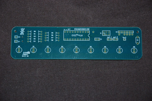
Here we have the humble “ix v 0.9” board, used for both the Larson Scanner Kit as well as the Deluxe LED Menorah Kit. It’s a great board, and one of its biggest benefits is the addition of a section to solder on an ISP programming header as well as breakout sections for some of the unused pins on the great ATtiny2313 chip.
To make your Larson Scanner expandable, some minor changes are necessary. Some of these are wiring changes, some are programming changes, but all changes should be fairly easy to make to either a completely assembled Scanner, or a fresh, unassembled Scanner (it should go without saying that starting from scratch will be a bit easier in the long-run).

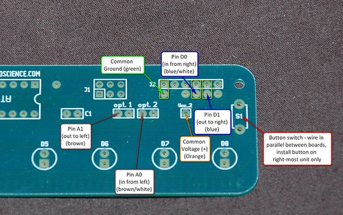
Here is an image showing some of the changes we will make, and the additional spots we will be using on the board. Click on the image to see the original, which is much easier to read.
The basic idea behind the expandability is this:
- Use A0, A1, D0, and D1 as inputs and outputs to/from the left and right
- Let each scanner manage its own LEDs
- Allow expandability without re-programming the chip each time you change the configuration
How do we do this? Well, we’ll need a new program (available for download here), a way to get it onto the chip, and we’ll need some wiring changes. The new program is intended for use with AVR-GCC and an AVR ISP programmer, such as the USBtinyISP. To re-program the scanner, you can either add a 6-pin header to the Larson Scanner itself, or use an ATtiny2313 Target Board or Development Kit with ZIF Socket to re-program the chips before they’re installed on the board.
In the mean time, let’s take a look at a close-up of some of the wiring changes on the right-hand edge of the board.
The basic wiring is fairly simple. I used an old ethernet cable that I had lying around, which was already missing an end, and cannibalized it for its twisted pairs. This is a great source of small wires for these sorts of projects, and the fact that there are 4 different colored pairs makes it fairly easy to create a wiring color scheme that makes sense.
One of the things to keep in mind is that, in order to “send” a signal to a different board,
the boards must share a common ground. And, since we can power 4 or 5 Larson Scanners on a single pair of AA batteries, we can also share a common positive voltage across the units, eliminating the need for multiple battery packs.
The concept is somewhat simple: To send a signal to the next unit to the left, you tie pin A1 (brown) of one unit to pin D0 (blue/white) of the other unit. To send a signal to the next unit to the right, you tie pin D1 (blue) to pin A0 (brown/white) of the next unit. You can then daisy-chain up to 4 or 5 units in a row in this manner off of a single battery pack.
To terminate the end of the chain, tie the output of that end (blue to blue/white on the right, brown to brown-white on the left), and the scanner will reverse course when it reaches the end.

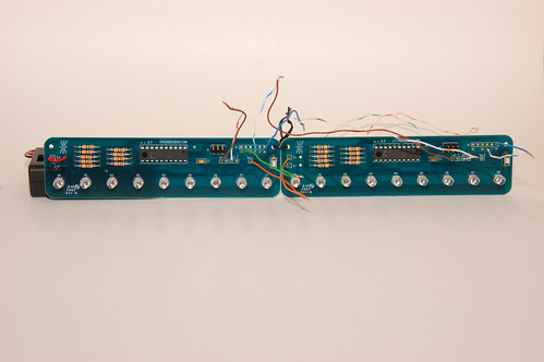
This picture shows how you would wire a single unit. Note how the blue-blue/white combo and brown-brown/white combo are tied. There is also a stray common voltage (+) and common ground (-) hanging off of the unit, so that we can connect it to a second
scanner later.
And here is a video of the single scanner.
Note how the new default behavior is to let the “eye” disappear off the edge of the unit. This is purely a style choice on my part (it IS Open Source, after all). Holding the button at startup will “soft-bounce” the eye on the edge of the scanner, although, once again, I took creative license by letting the eye parts “collect” on the edge, instead of bounce back and overlap with other eye parts.
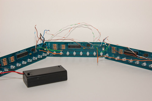
And now, of course, two units hooked together. Note the wiring, with the ends “terminated” by their respective colors, and the output of one tied to the input of the other. The final installation or use of the unit should dictate where you run your wires, of course, but they’re been placed in front of the board for ease of description as well as to work with the
through-hole design of the board.
A valid question to ask at this point would be, “but, how does the wiring tell the unit if it’s at the end of the chain?” The answer is that, technically, it doesn’t.
The new code has an initialization procedure built into it at startup that determines how the board is wired. The code latches the left-hand output, checks to see if the left-hand input has been triggered (indicating that it’s the end of the chain), and if so, it sets a flag that this is the left-most unit. Then rinse and repeat for the right-hand outputs. Other parts of the code then handle the position of the eye and determine if the scanner needs to trigger the next one in line, or simply bounce the eye back in the other direction.
Coding it this way means that the same code can be used on every single scanner in the chain, without having to re-program it any time you change the configuration.
And what good would it be to have a still image of two units hooked together without a
video of it?
And, finally, since I needed to test to see if the code and concept worked beyond two units, I grabbed an old scanner that has seen better days, re-programmed it, and wired it up. Below is video proof of concept. :)
The new source code is heavily commented, but if you have any questions, you can discuss it in the Larson Scanner Kit forums.
If you’re new to AVR programming and/or want to hack further, you might want to
start by looking at EMSL’s list of resources for getting started with AVR microcontrollers.
I had a lot of fun hacking the scanner and documenting the process, and many thanks to Windell and the rest of the EMSL crew for inviting me to write this guest post.
I hope you enjoyed this installment, and I hope you have fun making your own super-long Larson Scanners for Halloween!
Nice work, it opens up a lot of new possibilities. It sounds like this would be infinitely scalable as long as you could provide power? Is there a practical limit to what size you could do with a plug pack?
The first thing I though of when reading this are the emergency chase lights you see on the floors of Sci-FI movies. You know the sort, follow the light to the exit. I think Aliens had them… The eye never bounces back in those set ups though. I guess you could either program it to let the eye die once it reaches the end, or use a long, hidden wire to put them in a loop so the eye just wraps around, never reaching an "end". Of course you might also want multiple eyes on the line for long runs, or it could look anemic. Or make a larger eye? Maybe keep one small eye and set it to ludicrous speed.
I think I need one or more of these kits now. >_>
Same here.
I’m going to need at least three more.
Cylon helmet, KITT and Jack O’Lantern.
would it be possible to loop the "eye" by connecting the brown and blue wires as if you were adding an additional scanner segment. placing a switch so at start up it thinks it is a single chain and then closing the switch so that when the eye reaches the end it triggers the first scanner to start again?
It needs a new board revision with headers on each end so you can do a simple daisy-chain :3
Someone may or may not be looking into that as I type this…
If I could only remember how to actually launch gEDA-PCB on my laptop…
This got picked up on Hack-A-Day yesterday:
http://hackaday.com/2010/10/14/larson-scanner-hacking/
What about publishing a jpg image with the PCB tracks? I’m practicing with acid-etched PCBs and would love to try this project
What about looking at the original article, where we show that already? ;)
Windell H. Oskay
drwho(at)evilmadscientist.com
http://www.evilmadscientist.com/
so when you add another set of 9 LEDs, do you have to reprogram the AT tiny? or is it preloaded with code to detect the configuration?
"How do we do this? Well, we’ll need a new program"
So, yes, a new program is needed, for both units. It’s linked to within the article, as well as details on how to re-program.
Is it possible to have something like a knob added to adjust the speed of the light? This would be a good affordable project for people suffering from PTSD. The treatment is called EMDR that uses something similar. The patient follows the lights with their eyes and it produces a waking REM type state to help process the traumatic event. The lights would be in a mounted in a bar light as shown at http://www.neurotekcorp.com/eyescan.htm. Except it wouldn’t cost $400+ to make. This could be a great project to help out millions of people by providing cost effective alternative. Would love to see this.
The push-button already gives you a choice of three speeds. I’m pretty sure it would take only a trivial amendment to the code to allow that to change the rate in much smaller increments if you required finer control.
For an actual knob, you would either need an analogue input or some sort of digital encoder that would give a digital pulse when it was turned. That would probably need an extra port or two but I’m sure some of the programming ports could be pressed into action and they are all accessable. I find it hard to believe that the change to the code would be significant.
In summary, I’d be surprised if this was difficult.
Adding fine button control would be very straightforward. However, the ATtiny2313 chip on the Larson Scanner does not have an Analog-to-digital converter, so adding a knob would not be very easy.
Windell H. Oskay
drwho(at)evilmadscientist.com
http://www.evilmadscientist.com/
Could something equivalent to a mouse scroll-wheel not be added and interfaced digitally?
Yes, what you’d normally call a rotary "encoder" would work for that.
Windell H. Oskay
drwho(at)evilmadscientist.com
http://www.evilmadscientist.com/