


Today we’re releasing a new open-source project and kit, which is an updated approach to the “Larson Scanner.” The Larson scanner is named in honor of Glen A. Larson, the man responsible for producing both the original Battlestar Galactica and Knight Rider television shows, and consists of a set of red LEDs that scan back and forth.
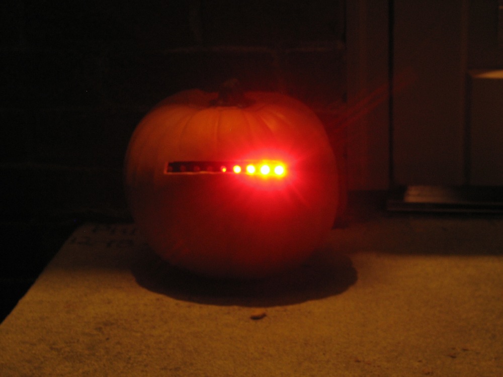
Three years ago, we showed how to make a Cylon Jack-O-Lantern, in what has become one of our all-time most popular tutorials. The circuit for that project was based on a 555 timer, driving a 4017 decade counter, and has 6 pixels of resolution. To create the incandescent fading effect, we added low-pass transistor drivers. We also wrote up a version of that article for the 2007 Make Magazine Halloween special, which included a slightly nicer version of that same circuit.
And while it’s been popular, we’ve always had some nagging reservations about it, and in particular its battery life. This year, we decided to do something about it and made a much betterversion of the Larson Scanner, and so here it is:
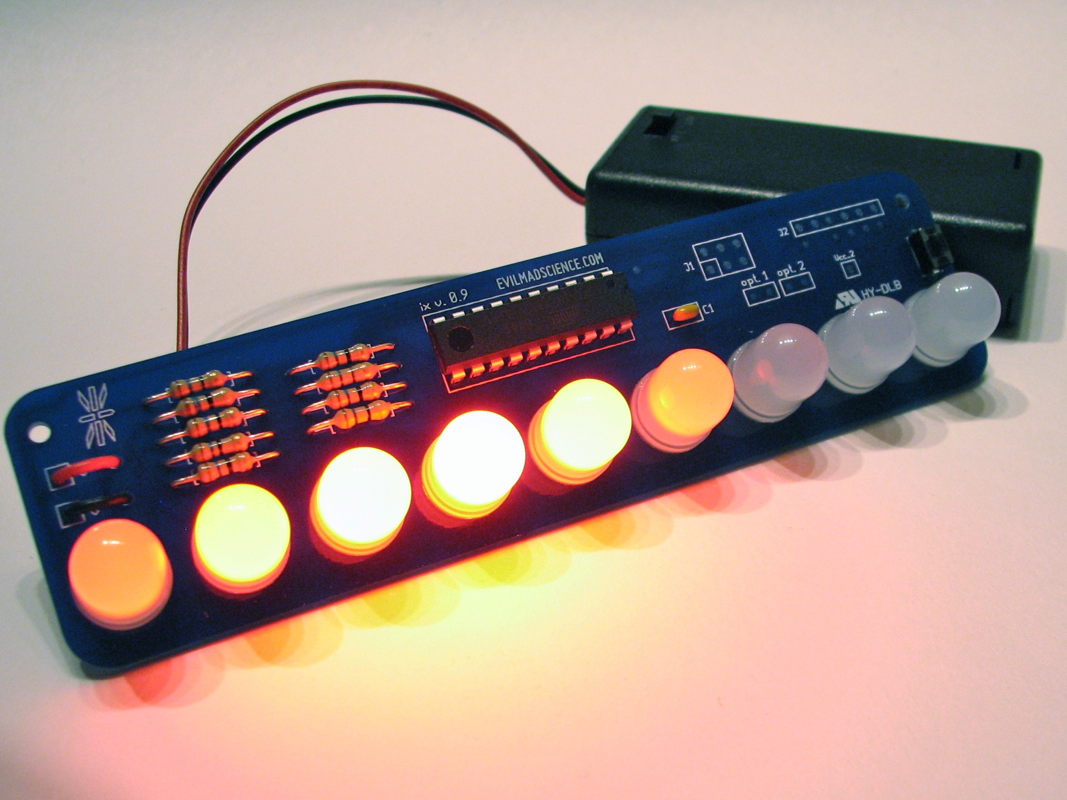
The all-new Larson Scanner is based on the ATtiny2313 microcontroller and has a few distinct advantages. First and foremost, it’s power efficient. While the old version based on the 555 and 4017 can be built from off-the shelf parts, it’s also a power hog, and battery life on that circuit is anything but impressive. The new version uses a low power microcontroller, and carefully manages the power to the LEDs.
Speaking of LEDs, we now have nine rather than six, and as the “eye” scans from back and forth across the LEDs, it now has silky smooth animated fading between them. To achieve the smooth scanning, up to five of the LEDs may be lit, to various degrees, at any one moment. Greyscale is achieved through high-speed software based pulse-width modulation. It’s digital but very efficient, and it looks genuinely better than any of our previous versions.
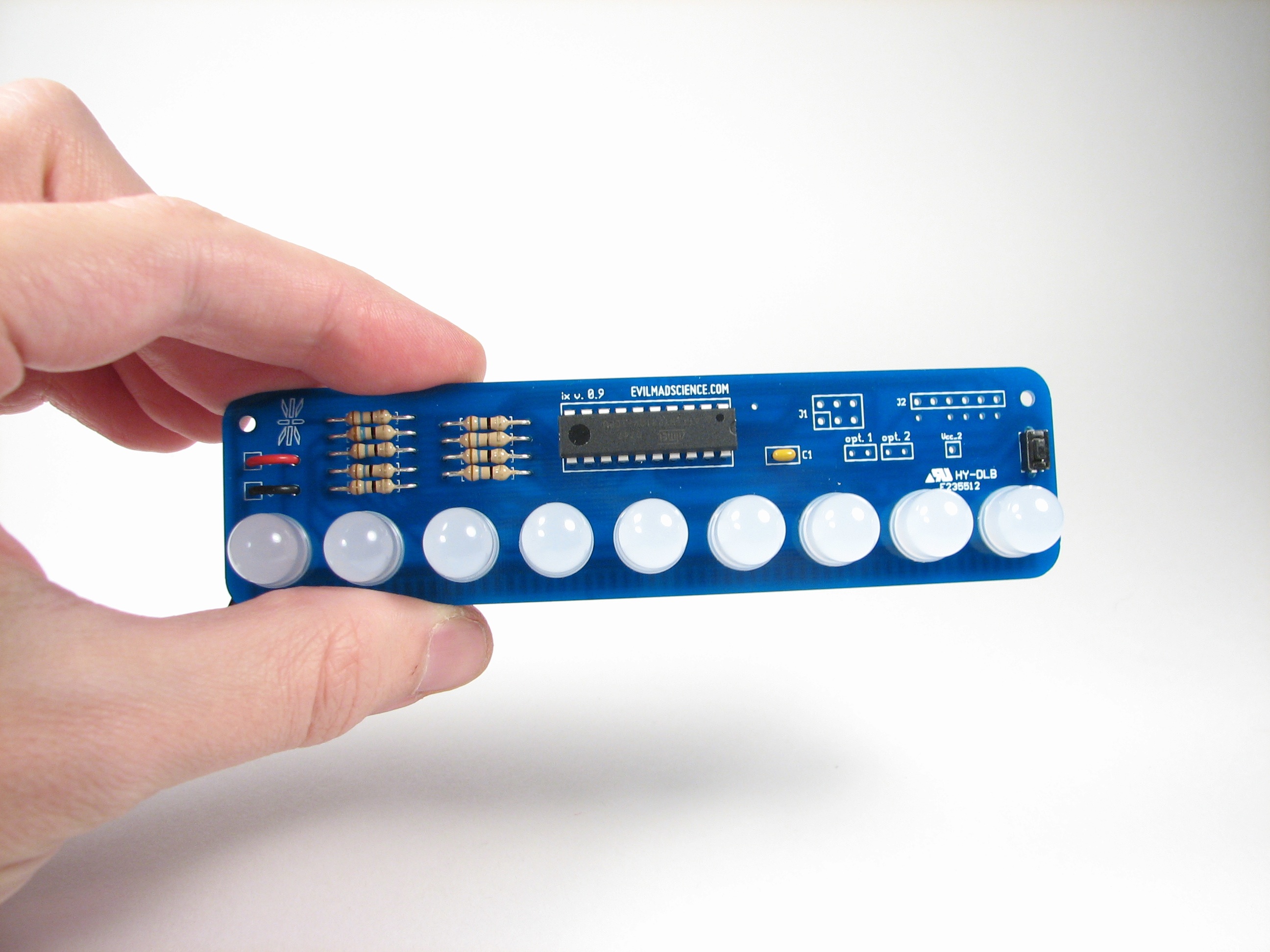
The LEDs and microcontroller have been laid out on a relatively spacious 5 inch long (12.7 cm) circuit board– big enough to fit 10 mm LEDs –and it all turns out to be the easiest to assemble kit that we’ve ever designed.
While we did incorporate a rate adjustment trimpot in the later version of the 555-based scanner, it’s actually not that convenient to adjust. In the new version, there is a pushbutton switch located on the right side of the circuit board. Pressing it allows you to choose between three basic scanning speeds (“slow,” “medium,” and “fast”), all of which use the same smooth scanning.
If you hold the button for several seconds it will also toggle the scanner between two modes: the default low power mode, and high-brightness (aka “annoyingly bright” mode).
The circuit runs on 2 AA cells, and has an external battery box with integrated power switch. Under high-brightness mode: A new set of alkaline AA cells would be expected to last about 60-80 hours continuously, or 10-13 days if run 6 hours per day. Under low-power mode– the default at turn on– a new set of alkaline AA cells would be expected to last somewhere in the neighborhood of 400-700 hours, or 16-30 days if run continuously.
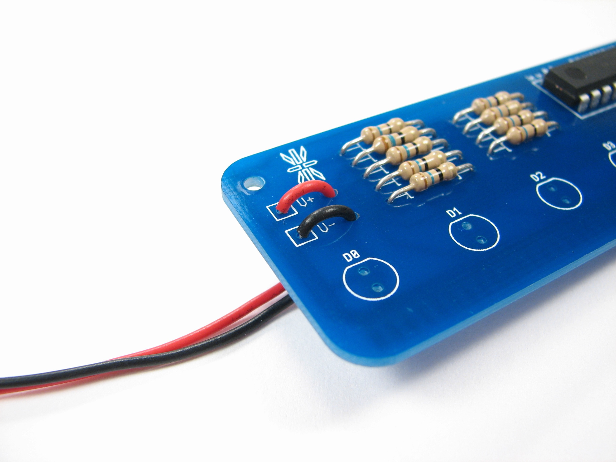
One more neat trick: The battery box wires go up through holes in the board before looping around to get soldered in place. We got the idea for this nice strain relief from Dale Wheat who uses it in his own tiny kits.
This is an open-source project, designed to be hackable.
The circuit board in the Larson Scanner kit is called “ix,” as in Roman for the number nine, because it has nine LEDs onboard. To get started working with this design on your own, you can download its schematic diagram here (33 kB PDF file).
If you look at the schematic, you might find a couple of places to put extra interfaces: you can add an on-board AVR-ISP programming header and even a header to connect to a FTDI USB-TTL serial cable, just in case you want to reprogram it to talk to your computer. There are also two locations to add jumpers– permanent or removable header-type –for user control of the hardware.
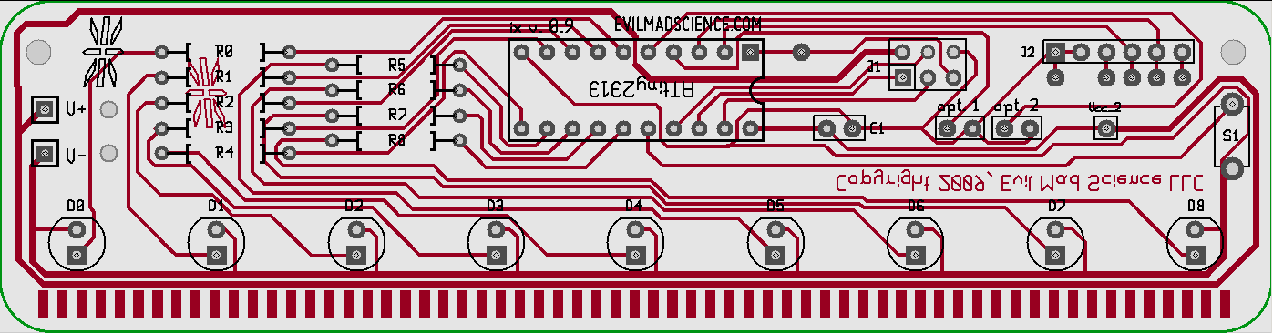
You can download the circuit board layout file here (74 kB .pcb file);
The circuit board was designed in gEDA PCB— free, open-source printed circuit board software. Since this is a single-sided design and relatively easy to make as a home-etched circuit board, you may also want to download this PDF of the PCB layout, showing the individual circuit board layers broken out individually with crop marks.
The source code is available for download from our
Google Code site. It’s designed for use with AVR-GCC and an AVR ISP programmer. If you’re new to AVR programming and want to hack the Larson Scanner, you might want to start by looking at our list of resources for getting started with AVR microcontrollers. You may also be interested in this article about expanding the Larson scanner with an alternate version of the source code.
The Larson Scanner kit is available at our webstore.
Additional documentation about the Larson Scanner kit is available at our documentation wiki.
Want to talk about this project? That’s what our forums are for.
Got projects based on this board to show off? We’d love to see your pictures in the Evil Mad Science Auxiliary.
You can find more pumpkin projects in our Halloween Project Archive.
Why don’t you guys put a piece of diffusing plastic over the LEDs like you did with the Peggy 2 RGB board? That would smooth out the lights even better.
You certainly can; the 10 mm diffused LEDs already do this to some extent. An external diffuser might look pretty good on a pumpkin.
—
Windell H. Oskay
drwho(at)evilmadscientist.com
http://www.evilmadscientist.com/
You could accomplish this by carving the pumpkin very thin, but not all the way through.
So how come the old circuit was such a battery hog? I would have expected that the vast majority of the power would have been consumed by the LEDs rather than the 555/4017 (especially if you used a cmos 555), so I don’t see how going to a "low power microcontroller" saves much. Of course, you’re also going from linear "brightness regulators" to switch mode (sort of)…
The real culprit is if you use a "real" non-cmos 555– the supply current at 9 V is about 6 mA. (That may not seem like a lot, but the *total* current for the digital version is under 5 mA in low-power mode.) The 7555 is much better of course!
The second reason is also mostly obvious. The original circuit was powered by a 9V battery, which has only about 1/3 the capacity in terms of mAh when compared to AA cells. The higher voltage (9 vs 3) helps to run our driver circuit, but that extra voltage isn’t really needed or helpful for driving the LEDs themselves, so we don’t use the energy in the battery as efficiently– we just burn it off in resistors.
—
Windell H. Oskay
drwho(at)evilmadscientist.com
http://www.evilmadscientist.com/
please forgive a silly question:
it seems to me that you could put one resistor between ground and all of the LEDs. The way this is built, it looks like each LED has it’s own resistor. Not like resistors are that expensive or anything, but it seems to me like you could just use one and have a bit less soldering to do. It isn’t an important question, I was just curious.
If we only had one of the LEDs on at a time, that would be true. If two of the LEDs are on at the same time, but are connected to a single resistor, then the tiny differences between the LEDs would lead to imbalanced current between the two, and one of the LEDs would tend to be brighter than the other.
—
Windell H. Oskay
drwho(at)evilmadscientist.com
http://www.evilmadscientist.com/
thanks. That makes sense.
Is it possible to see a video of the new scanner in action?
-radiodork
We haven’t made a video of it yet, but we will do so soon. :)
—
Windell H. Oskay
drwho(at)evilmadscientist.com
http://www.evilmadscientist.com/
Can two leds be attached to each point? I have a project where I’d like two moving lights moving towards and away from each other, similar to the scanner on the most recent knightrider series.
You could do it if you put two LEDs in series at each normal LED location; you would need to increase the system voltage from 3 V to (say) 4.5 or 5 V, with a corresponding change in the resistors as well.
Much better would be to just to mount two of our kits (kitts?), and mount them side by side. It wouldn’t be a difficult programming change to sync them together.
—
Windell H. Oskay
drwho(at)evilmadscientist.com
http://www.evilmadscientist.com/
What if we wanted to link 2 larson scanners together so that there were 2 lines of leds that moved at exactly the same time (rather than making a longer single run)? I’m making a daft punk helmet where there would be 2 runs of lights, both being synced at opposite sides of the helmet. In this case, wiring 2 leds in series at each location seems to be the best option (with the change in resistors for white leds and double lights) – but I’m trying to avoid programming and using Arduino. is this possible?
Thanks.
>What if we wanted to link 2 larson scanners together so that there were 2 lines
>of leds that moved at exactly the same time (rather than making a longer single run)?
Each microcontroller operates independently. If you want to synchronize them somehow, it will require some method of doing so. It’s just about trivial as a software change, but if you don’t want to do that, there’s not really any way.
>In this case, wiring 2 leds in series at each location seems to be the best option
>(with the change in resistors for white leds and double lights)
I’m not sure what changes you’re referring to here. If you want two lines that move at the same time, it might be worth controlling more than one LED from each LED. You can’t directly run two white LEDs in series from each LED output; there isn’t enough voltage for that.
– but I’m trying to avoid programming and using Arduino. is this possible?
I’m not sure how Arduino got into this, but yes you can avoid programming. You can wire up the signals from the microcontroller to control many, many LEDs per output, but you’ll need to provide appropriate power supplies and potentially LED driver electronics as well. If you’re more comfortable with electronics than programming, you may want to build the original 555 version instead; it can be hacked as well.
Windell H. Oskay
drwho(at)evilmadscientist.com
http://www.evilmadscientist.com/
ok, thanks, this is good info. so in a nutshell, I can wire 2 leds in series from each, getting 18 leds in 2 strings that run in sync – but I need to supply more power. even if all of the leds are white, i still don’t need to change the resistors?
I was thinking I would need Arduino to program 2 scanners to run in sync, but apparently I can do that with jumpers or something?
Thanks again.
>so in a nutshell, I can wire 2 leds in series from each, getting 18 leds in 2 strings
>that run in sync – but I need to supply more power. even if all of the leds are white
No– You cannot run two white LEDs in series directly from any output on the chip. A white LED needs at least 3 V to operate, usually closer to 3.6 V. We recommend powering the chip at 4.5 V, with the 16 ohm resistors, to deliver the proper 3.6 V to each LED with associated losses in the chip and an appropriate current output. If you want to run *two* LEDs in series from one of those outputs it requires *at least* 7.2 V, but the chip is only rated for 5.5 V.
>I was thinking I would need Arduino to program 2 scanners to run in sync,
>but apparently I can do that with jumpers or something?
Again, I’m not sure how Arduino got into this. These chips aren’t normally used in conjunction with Arduino. Yes you can program an Arduino to work as an AVR programmer, but it seems like this is a bit of a roundabout method for someone who doesn’t want to do much programming. (To use the car analogy, you’re asking how to hook up a trailer to your pickup, and asking if you need to use a minivan to help with the hookup. Yes, you can probably hook it up to a minivan, but that’s not really relevant.)
I don’t know of any way to reprogram the larson scanner kit to do something different just by changing jumpers either, so I’m not sure where you got that idea.
All of what you are trying to ultimately accomplish is possible, but it requires some degree of patience and understanding. Nothing happens by magic.
Windell H. Oskay
drwho(at)evilmadscientist.com
http://www.evilmadscientist.com/
The leds look awfully big, just from looking at it without any pictures/video it seems like it is going to be really nasty looking.
But not as nasty as that last comment. ;-)
—
Art Dahm • My Peggy 2.0 Web Page • http://www.mindlessdiversions.com/peggy2/
The 10 mm LEDs are really quite lovely; and our kits come with a choice of 5 mm LEDs as well.
—
Windell H. Oskay
drwho(at)evilmadscientist.com
http://www.evilmadscientist.com/
What is the value of the resistors? The schematic says 10 which I assume is 10 ohms and the pictures show 16 ohm resistors (if I’m reading the resistor band codes in the photos correctly). I have some leftover 10mm diffused LEDs from Peggy 2 and an ATtiny2313 target board which I can use with the software. Thanks.
—
Art Dahm • My Peggy 2.0 Web Page • http://www.mindlessdiversions.com/peggy2/
> What is the value of the resistors?
The kits are shipping with red LEDs and 16 ohm resistors. You’re quite observant!
>I have some leftover 10mm diffused LEDs from Peggy 2 and an ATtiny2313 target board which I can use with the software. Thanks.
If you have red or yellow LEDs and 3 V, then that should work fine. If your LEDs are green, blue, or white, you’ll need to provide more voltage to drive those LEDs, with a corresponding change in the resistor values.
—
Windell H. Oskay
drwho(at)evilmadscientist.com
http://www.evilmadscientist.com/
According to the AtTiny2313 datasheet the I/O lines are capable of driving only 40 mA per I/O pin, and 200 mA total for the part. That computes to about 57 ohms for the series resistor minimum. 3V(Battery Voltage) – .7V(LED drop) = 2.3V / 40ma = 57.5 ohms. Have you had any reliability issues with overdriving the I/O lines on the Atmel processor? I realize that the tiny on times of the pulses produce a lower average current, and that LED reliability, and heat dissipation in the processor will not be a problem, but won’t it affect the reliability of the driver buffers themselves to overdrive them this way?
We’re well aware of the current limitations on the ‘2313, and we are operating within them.
The forward voltage of typical red LEDs, i.e., the voltage at which they conduct about 20 mA, is roughly 2 V. Pulling a full 40 mA requires closer to 2.1 – 2.3 V. The AVR, when powered by 3 V is specified to put out a minimum of 2.5 V on its GPIO output lines, but let’s assume that you get a full 2.7 V out.
Then… to get 40 mA limited output, you should pick 0.6 V / 40 mA = 15 ohms minimum, where 0.6 V = 2.7 V- 2.1 V. If you’ll notice, we use 16 ohm resistors. We also don’t drive 5 LEDs continuously, so we won’t violate 200 mA output.
That all said, we have (in other projects) driven red LEDs at low duty cycle directly from the outputs of an AVR running at 3 V. In this case you might see current in excess of 50 mA instantaneously. Even in those projects, we have not seen degradation of the microcontroller even under months of sustained operation.
—
Windell H. Oskay
drwho(at)evilmadscientist.com
http://www.evilmadscientist.com/
So I’m an electronics noob here and I’m looking at my set of White LED’s and on the package it says:
Forward Voltage (V) : 3.2-3.4V
Current: 20MA
Now you said you’re red LED’s are already drawing 20MA with 2 batteries. Would I have to add more batteries for my white LEDs?
Is this for LEDs in general, or for the Larson scanner kit? In either case, the place for Q&A like this is in our forums, not here.
Windell H. Oskay
drwho(at)evilmadscientist.com
http://www.evilmadscientist.com/
Which frequency do you use to clock your AVR? And which PWM frequency and bit-depth (for brightness fading) are you able to achieve with it?
The AVR is clocked at 512 kHz, which is *very* helpful in reducing the power consumption of the device.
The PWM is managed through software, and is frequency is variable depending on the power mode– you may want to look at the source code to see how we do it. 60-70 levels of brightness are used, also depending on the mode.
—
Windell H. Oskay
drwho(at)evilmadscientist.com
http://www.evilmadscientist.com/
While there don’t appear to be any hooks for opt1 and opt2 in the provided code, I understand how they might be used (e.g. to synchronize multiple kits.). I don’t have any clear idea why Vcc2 was exposed on the board right there. Can you point me in the right direction?
The option jumpers could be used for any number of things with additional programming– yes sync, but also to disable high power mode, configure serial interface, and so on.
Location J2 is a header for an FTDI USB-TTL cable. If you attached a header and one of those cables, you could then hook up the board to your computer through USB. The FTDI cables can provide power ("USB power") to a board that they connect to, either 5 V or 3.3 V depending on the model. We provide two holes– Vcc_2 and the unlabeled hole directly above it –that you could wire across to make your board USB powered.
(Note: If you run from 5 V, you will need to make a corresponding change in the resistors.)
So, it shouldn’t be too hard to make a USB-powered Larson scanner. If you want to make it USB-controlled as well, that will take a little more work on the software side.
—
Windell H. Oskay
drwho(at)evilmadscientist.com
http://www.evilmadscientist.com/
I am familiar with FTDI, I’ve got a 5V FTDI cable already, quite handy (I’ve also got a USB TinyISP)
I missed entirely that it was aligned with Vcc from the FTDI cable. Very clever. Is there a serial library available for the Tiny2313, or would I just have to bit-bang the serial interface?
— Mitch
> Is there a serial library available for the Tiny2313, or would I just have to bit-bang the serial interface?
Not that I have looked, but I’m not aware of any good “high level” serial library for the ‘2313. It’s resources are very limited, and setting up long serial buffers is not necessarily what you want to do. However, you certainly don’t need to big-bang it either. The ‘2313 has a genuine hardware serial port and details about how to use it are given in the datasheet. The serial port *is* supported by AVR-Libc, in the same way that GPIO and other microcontroller functions are normally used.
For a halfway step between reading the datasheet and using a true high-level library, you might want to check out an example project that we did recently: http://www.evilmadscientist.com/go/avrserial.
In that project, we give a code example for serial communication on the ‘2313, complete with higher-level serial routines, including establishing contact with a host program on the computer.
—
Windell H. Oskay
drwho(at)evilmadscientist.com
http://www.evilmadscientist.com/
Is there a way to make this run from a 12v DC source? How about a way to make it waterproof? Thinking of this in the front grill of a snowmobile for kicks. Also looking for the dimensions of the kit circuit board and the dimensions of just the leds. Thnaks
The easiest way is to use a voltage regulator to step down from 12 V to 3 V. Waterproofing is not straightforward; you can encase it fully in plastic, but then you won’t be able to access the switch unless you wire that off board.
The circuit board is 5" x 1.3," and the "10 mm" LEDs shown here are approximately 11 mm tall.
—
Windell H. Oskay
drwho(at)evilmadscientist.com
http://www.evilmadscientist.com/
I am not yet very knowledgeable in electronics, but I am trying. :-) If you would, I sure would appreciate some guidance.
I too am trying to do something with a 12V source (custom car headlights). Do I have to voltage regulate down? I would like to draw my power from the turn signal. Wouldn’t the 12V give me more intensity? I plan on using “12V ready” LEDs, so I think my question is can the microcontroller and the capacitor handle the 12V? I am assuming that I would need a different capacitor. True? If yes, what do you recommend?
I recognize that may have no idea what I am talking about, but I hope I am not too far off.
The microcontroller cannot run directly off of 12 V, and it cannot run "12 V LEDs." There is no standard component that is a 12 V LED, rather most of them are simply a normal LED paired with a resistor appropriate for using with 12 V. Our setup is designed to run at 3 V, and includes the necessary resistors for 3 V operation. Again, the easiest way is to use a voltage regulator to step down from 12 V to 3 V
—
Windell H. Oskay
drwho(at)evilmadscientist.com
http://www.evilmadscientist.com/
How smooth is the fading? Are there any videos available?
What is the part number/vendor of that nice little switch, and which LED’s do you use for the 10mm size (part number/vendor)? Thanks
The switch is Digi-Key part number CKN9102-ND. The 10 mm LEDs are the ones from our web store: http://evilmadscience.com/partsmenu/89
—
Windell H. Oskay
drwho(at)evilmadscientist.com
http://www.evilmadscientist.com/
Along the bottom edge of the circuit board, there is a row of unattached rectangular solder pads. For what purpose did you envision these pads would be used?
These aren’t actually intended as solder pads– they’re to provide friction if you slide the circuit board lengthwise into a holder of a particular shape.
—
Windell H. Oskay
drwho(at)evilmadscientist.com
http://www.evilmadscientist.com/
Thanks for this – I built the kit yesterday with my 8 year-old helping to clip the wires. My first kit! Peggy 2, here I come!… OK, maybe I need a few more little things first.
Thanks for this – I built the kit yesterday with my 8 year-old helping to clip the wires. My first kit! Peggy 2, here I come!… OK, maybe I need a few more little things first.
Just assembled a 5 mm and 10 mm kit. The LEDs in the 5 mm kit are painfully bright. The 10 mm LEDs are made of awesome. :)
Love this kit, was fun to build – posted some pics of my not so good soldering skills at ensoftinc.wordpress.com. Keep up the good work!
Just got my two kits today, put the first one together. It worked great, but the 3rd light didn’t go on. After tracing around with an ohm-meter, and resoldering the joints on that path, I decided that the path from the chip to the first resistor was bad, so I soldered a wire on. That did the trick.
Second one went together just fine.
I also had problems with LED#3 but after trying to replace the LED (assuming this was the problem – an ohmmeter check seemed to indicate power was getting to the pins) I damaged the ground line to the LED. Bad on me; I will use it as a 6 LED Cylon pumpkin next year …
If you’ve managed to dislodge the ground line, you can almost certainly add a jumper wire from one of the other ground lines on another LED. If the connections are not strong enough to hold the LED in place, you might consider assisting with a small dab of epoxy.
—
Windell H. Oskay
drwho(at)evilmadscientist.com
http://www.evilmadscientist.com/
Thanks to Lenore M. Edman for keeping me "In the Loop" as far as shipping. Package arrived with only one resistor a little bent. Great job USPS. Built in one (1) hour. Only change made so far was to use a 20 pin dip socket for the ATtiny2313. Going to convert to USB power for next upgrade. If anyone(why re-invent the wheel) has already done so post please. Also thinking about installing it as drive activity light on my computer. So many projects, so little time. At any rate Great Kit guys.
>Going to convert to USB power for next upgrade.
If you use the USB-TTL cable, there’s a location to put a power jumper to VCC: Check the circuit diagram and circuit board layout. Be sure to change the resistor values if you go for a higher drive voltage, though.
—
Windell H. Oskay
drwho(at)evilmadscientist.com
http://www.evilmadscientist.com/
I also use gEDA/PCB as a schematic capture & circuit board layout tool. I was curious, what board house do you use to product your boards? I am looking around to find places with better prices than the place I am currently using (PCB Express).
We’ve used PCBexpress with good luck– they make excellent boards — but they just raised their prices. They do have a new service, ValueProto, which is less expensive. We get our boards made at a few different houses. Our most recent order of circuit boards was from Advanced Circuits.
—
Windell H. Oskay
drwho(at)evilmadscientist.com
http://www.evilmadscientist.com/
Just built the scanner. Terrific project. I’d like to offer some things to help make your projects/products even better:
1 – the instructions are very clear and straight forward. Nice work.
2 – you might include a few assembly times for budgeting. I consider myself fairly experienced – it took me about 25 minutes from cracking the package to working circuit. I would expect about an hour for a novice.
2a – You might want to also include hints to help novices get better. For example, I did the resistors in two sets (one for each column), and I pulled the resistors out of the tape in a way that bent them as they pulled free.
3 – I would be happy to see a download-only instructions option to save a few trees, especially if you deducted the print cost
4 – Both kits had 10 resistors and 10 LEDs, contrary to the instructions – perhaps the instructions should say "10 resistors (9 + 1 spare)"
5 – Although I can tell that the kit is geared for beginners, it’s still nice to have the entire manifest spelled out in detail in the instructions (ie, 16 Ohm resistor (10), 0.1uF capacitor (1)). I know I can pull the schematics, but one-stop shopping is nice.
Nice work!
Side note – although the firmware would be more complicated, this strikes me as a circuit that would work well with Charlieplexing, allowing you to use as few as 4 I/O pins for the LED’s and a 5th for the switch which might allow a smaller/cheaper part.
When using the FTDI-232R-3V3 cable with Atmel processors with direct wire connection (No MAX232 chip) do you use the default settings for the FTDI chip, or do you need to invert the TXD and RXD signal polarity in the FTDI chip’s EEPROM with the FTDI configuration program FT-Prog? By studying the schematics and documents on the FTDI web site, I was unable to determine the default polarity of the TXD and RXD signals with respect to the default Atmel chip polarity.
I believe that it works with default polarity; we’ve never had to muck with those settings.
—
Windell H. Oskay
drwho(at)evilmadscientist.com
http://www.evilmadscientist.com/
I just heard back from Atmel concerning a comment that I sent them. I asked them why they don’t offer additional flash size options for the AtTiny2313 as they do for many of their other chips. They announced that they will soon release the AtTiny4313 with 4K of flash. This will be a much more useful processor than the AtTiny2313 with only 2K of flash. There have been a number of designs where I had to upsize to the AtMega chips merely because of flash size. The AtTiny2313 would have been more pin count compatible if it had just a little more flash.
I thought you all would like to know in case you hadn’t heard already.
That’s excellent news– thanks!
—
Windell H. Oskay
drwho(at)evilmadscientist.com
http://www.evilmadscientist.com/
Very nice kit! I just got it in the mail today (thanks, Lenore!) and got busy putting it together. I must say this is a very well-made kit. It goes together quite well and the instructions are a real treat. I’ve posted some photos on my web site:
http://dalewheat.info/lasron-scanner-from-evil-mad-scientist-labora
Good work! Happy Halloween!
WOW. You guys made CNN!
I installed my Larson Scanner in my pumpkin this year…I got a compliment on my "cylon" from one of the parents shepherding trick-or-treaters around. Here’s my video:
http://teawithbuzz.wordpress.com/2009/11/01/jack-olantern/
I use these kits to not only have fun making something cool, but I am trying to learn about electronics. I am a little confused why the 16 Ohm resistor is being used. I sure would appreciate some intelligence thrown my way.
When I use the following “Single LED”calculator: http://metku.net/index.html?sect=view&n=1&path=mods/ledcalc/index_eng
With these values:
Supply Voltage = 3 VOLTS (2 AA)
Voltage Drop Across LED = 2 VOLTS (red LED)
Desired LED Current = 15 MILLIAMPS (they suggest 15 – http://www.theledlight.com/LED101.html)
It suggests a 68 Ohm resistor. I assume I am not understanding something. I do not doubt you know what you are doing. I just want to understand why the difference.
There are additional voltage losses inside the microcontroller chip. Also, we can drive the current a bit higher– up to about 30 mA — for short periods of time. Picking that resistor value is an *art* for cases like this– the resistor calculators tell you what a good value for steady-state solutions– we’re scanning all of these LEDs thousands of times per second.
—
Windell H. Oskay
drwho(at)evilmadscientist.com
http://www.evilmadscientist.com/
Thank you! That makes sense. I appreciate your response. I am toying with the idea of trying a two-LED, or three, series, so I will need to try out my own electronic "artistic" skills. What is your estimated voltage loss from the minicontroller? I did not consider that.
Im new to this. How can I go about putting this together on a breadboards?
Follow the circuit diagram!
—
Windell H. Oskay
drwho(at)evilmadscientist.com
http://www.evilmadscientist.com/
I’m soon to build a custom PC for myself, and would like to add this kit (somehow) into one of the external slots (the case will have red LED fans inside, etc, so this would be a cool add-on). However, my knowledge on circuit-level electronics is very limited. I understand that you can modify this kit with a header (USB?) and FTDI cable, but I don’t know where to start in finding the specific type of cable, header, or how they’ll interconnect to the PC. It would need to be powered internally, I suppose using one of the USB headers on the motherboard. Assuming the header for the larson kit is also USB, what sort of cable should I be using to go between them at 3.3V? Or would it be simpler to use a step-down regulator and just use the 5V supply from one of the PSU’s molex connectors, stepped down to 3.3V? Sorry for the long post and ignorance, but I’m new to electronics on this level (putting together pre-made components isn’t so hard!).
Replying to myself, here. If the LEDs are the only concern with the 5V, then all I’d really need to do is get the appropriate resistors, correct?
Yes, you can run this directly from 5 V if you use larger resistors– roughly 120 ohm, I’d guess.
Windell H. Oskay
drwho(at)evilmadscientist.com
http://www.evilmadscientist.com/
Yeah, I calculated it yesterday to 150 Ohm, if I did things correctly. This will be a cool addition to this PC!
I am very new to this so keep that in mind while you read the following.
My idea is as follows
I currently have the 10mm kit and enough 10mm Green leds.
I would like to have a green and a red led in series per light.
I am not understanding what resistors I would need in order for this to happen.
The only thing you would need to change is if the red or green LEDs were diffrent outputs, if the green was 10mm and the red was 5mm you would need a diffrent ammount of resistors, the current stays the same if the output is the same.
I think you may be misunderstanding both the comment above and typical LED voltage requirements. Additionally, LED size (e.g. 5 mm or 10 mm) does not affect anything other than the appearance.
If you have older yellow-green LEDs, you should be able to swap them directly for the red ones. For a swap to pure green LEDs, you can replace the 2 x AA battery holder with a 3 x AA battery holder and use the same resistor values.
For running a red and a green LED in series in each location, it would be somewhat more complicated than that, and we haven’t really looked into it.
oh
In the code you aren’t setting the usual registers for PWM (OC0x, TCCR0x, etc). Are you effectively doing PWM with delays?
Yes, it’s software PWM, and it works very well for a device of this scope. Also, since the ‘2313 doesn’t have nine PWM outputs, it’s the only game in town. :)
Windell H. Oskay
drwho(at)evilmadscientist.com
http://www.evilmadscientist.com/
oh so that’s what one dimensional pong looks like.
Hey! I just put together one of these kits, and I just wanted to comment that you guys did a GREAT job on the instructions, and on the quality of the kit itself! It’s been over a decade since I built anything from a kit, and this scanner kit of yours is a dream to put together! Whomever came up with your comic book style assembly sheet, I’d like to buy them a beer! Clear, consise, and ENTERTAINING! (I’m going to reccommend this kit to a friend who teaches industrial arts at a local high school… if this dosen’t get kids enthused about electronics, I don’t know what will!)
We just assembled it (worked first time, very easy, thanks!) and made a video of it in action:
http://www.youtube.com/watch?v=cN51Wb1GSOU
Now just gotta figure out how to modify the code :)
I need to order replacement 10 mm diffused LEDs that match the ones supplied in the kit, is there an easy part number I could get to make sure I get the right style LED?
I would venture to guess that the superbright 10mm diffused LEDs on the LED page of the Evil Mad Science Store would be similar, if not the exact same:
http://evilmadscience.com/partsmenu/89-led
The spec sheet states that they are BetLux, part number BL-L101URW
Howdy! Bought the kit from the Makerbot Botcave yesterday. Had a blast assembling and plan on buying several more as gifts. However! The Scanner doesn’t power on, the battery pack becomes very hot very fast, and I’ve killed three pair of AA batteries. Presumably either user error and I failed somewhere while assembling the Scanner. Or I have a bad ______ something. I’ve seen a few posts about over-heating battery packs in the forums – but any thoughts/suggestions on troubleshooting? I’m all about hacking this and working myself, but just filed a short report for work and suspect consumers might share the same frustration. I’m ALL about fixing/hacking/problem solving – but would love some troubleshooting ideas to share with friends. Thanks!
Yes, sounds like you’ve got a significant error– *do not* try and operate it again until you’ve found the cause, because you’ll just waste more batteries. There’s probably a short circuit somewhere: an accidental connection between the two ends of the batteries. Three of the more likely causes are (1) the red and black wires to the circuit board were installed in each other’s positions (2) The chip is installed backwards (3) there’s an accidental solder connection somewhere between two places on the circuit board that shouldn’t be connected.
*However* — the comments section here is not the right place to debug the problem; it’s not conducive to back and forth discussion. If you can’t fix it on your own from those hints, please direct your issues to our support forum:
http://www.evilmadscientist.com/forum/index.php?forum=6
Windell H. Oskay
drwho(at)evilmadscientist.com
http://www.evilmadscientist.com/
This was my first soldering job, and i messed it up! I accidentally got solder in one of the transistor holes adjacent to the one that I was working on, in the process of desoldering that hole, the through-hole ring came off with the excess solder! Do you think this is why my kit doesn’t work? would one missing transistor through hole ring do me in like that? I imagine it would, b/c it seems like i did everything else just right.
There aren’t actually any transistors in the kit, so I imagine that you actually mean resistors.
The pads on the circuit board don’t normally come up with careful soldering, only when too much heat or pressure are applied. You should solder *gently,* applying heat only for a second or two, and without any pressure. With too much heat or pressure, circuitry on even the toughest boards can delaminate.
Regardless, a torn trace or missing resistor can’t (on its own) cause the whole circuit to fail. There may instead be a short circuit (an accidental connection between two things that shouldn’t be connected) or an open circuit (a lack of connection where there should be one). As with delaminating circuits, both of these are symptomatic of novice solder technique, and generally go away with some practice. So, take a look through your board, and try to figure out where the possibly bad solder joints (or accidental connections) might be.
If you need additional assistance getting your kit to work, please direct it to our forums– blog comments aren’t conducive to back and forth discussion.
Windell H. Oskay
drwho(at)evilmadscientist.com
http://www.evilmadscientist.com/
Cool kit, wish I had more time before Halloween, plenty of time for next year I guess.
My question: can the sweep rate be controlled better than s/m/f by adding a pot, or would this be a programming issue? What would be really sweet is to have that with a read-out of sweeps per minute. What I am thinking of is a silent metronome for music performance/recording. It seems like a simple thing but I haven’t seen one. Being new at wiring & all perhaps this could be a project to develop?
It’s not actually trivial to add a pot to this particular circuit, because the ‘2313 chip that we use does not have an analog to digital converter on board. It would certainly be possible to add additional speeds, and even to have the speed adjustable in 1 BPM increments with each button press, for example.
Windell H. Oskay
drwho(at)evilmadscientist.com
http://www.evilmadscientist.com/