


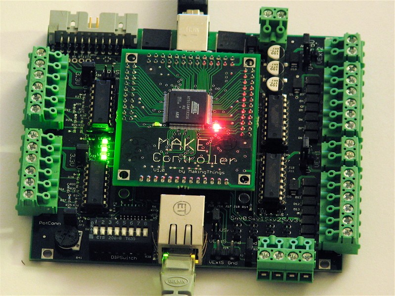
As evidenced by a growing collection of projects, the MAKE Controller has great potential as a hardware platform enabling computers to really do things.
We won a MAKE Controller for our set of Halloween projects this year, and we’re just starting to play around with it. Having spent some pondering how best to communicate with the board, it’s clear that one of the barriers to more widespread use of this and other embedded systems is the lack, or perceived lack at least, of user-friendly software for programming and communication.
A number of open-source software packages, such as processing and Ruby, can communicate with the MAKE Controller using its OSC interface. However, there has been a noticeable absence of a suitable interface to LabVIEW, a program that is commonly used for interfacing to other similar types of hardware.
So, we wrote one. It’s a simple LabVIEW “vi” routine for issuing (most) simple commands and queries to the MAKE controller. We’ve also included some example routines to help you get your blinky lights going a few minutes sooner.
Looking around at how people are using their MAKE Controllers, there are quite a few requests for help on interfacing to LabVIEW. LabVIEW is a proprietary and expensive, but de facto standard, software package that is commonly found in research and engineering laboratories.
This topic has been discussed heavily in the Make forums (example 1, 2, 3), as well as in the National Instruments forum. Unfortunately, it looks as though none of these discussions has yet provided a working solution, which is a situation that we hope to resolve.
The Make Controller, with its default set of firmware, accepts certain commands, over either USB or ethernet, in the syntax of OSC (Open Sound Control). OSC is not a computer programming language, but is rather a (slightly obscure) communications protocol that is apparently known by many multimedia-oriented musicians. In any case, OSC provides a structure for formatting commands that will be sent to the Make Controller. A typical command that you might send to the board is “/appled/3/state 0” (without the quotation marks), which commands LED number 3 on the Make Controller application board (/appled/3) to turn off (state 0). Other commands allow you to perform such tasks as reading analog and digital inputs, control DC and servo motors, and communicate over a serial port.
While OSC commands can potentially sent over several different interfaces, the ethernet interface is arguably the easiest to implement through LabVIEW in a manner that is independent of LabVIEW version and platform. Command data packets can be sent to the board through UDP, which is one of the standard internet protocols, and happens to be well supported in LabVIEW. (The discussion in the National Instruments came very close to providing a working solution using UDP, but had some errors in details of the OSC protocol.)
Before you get started…
The LabVIEW routines assume that you already have a good connection, over ethernet, to the MAKE Controller. Before you even try these programs, make sure that your computer can see the board. A good way to do this is to look at the built-in web server, at address 192.168.0.200 . You should have the default “heavy” firmware installed for the Make controller to be able to speak in OSC with you.
If you haven’t done this yet, please go through the tutorial on getting started with the Make Controller.
Interfacing LabVIEW to OSC
The LabVIEW routine “labviewOSC.vi” implements a partial subset of the OSC protocol, and is designed to allow basic communication with the MAKE Controller. Essentially, the program receives a text string and performs some minor manipulations in order to fit that string into a packet that complies with the OSC Specification. It then sends that packet over UDP to the MAKE Controller, which is (presumably) listening.
Here is how a minimal implementation of OSC communication looks in LabVIEW:
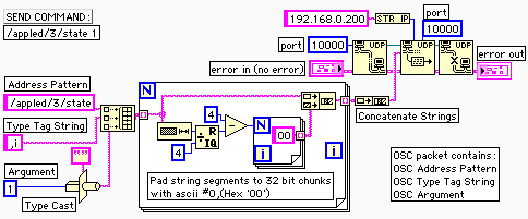
This code sends the command string “/appled/3/state 1”, which turns on (turns to state 1) LED number 3 on the MAKE Controller application board. You can read more about the application board LED (appled) commands here in the OSC command reference.
In order to successfully form the OSC packet, we first separate the “address” portion of the command string ( /appled/3/state ) from the argument (1). The address is sent as a regular text string. After the address comes an “OSC type tag string,” which indicates that the data following that tag will be an integer. Finally, the integer argument itself is sent, after being type cast to a binary (rather than ascii) representation. One of the restrictions on the length of OSC packets is that the whole, and some of the parts, are integer multiples of 32 bits (four bytes). The large box in the middle of the diagram is a FOR loop that adds extra ascii null characters to appropriately pad the length of the packet.
A useful LabVIEW interface for the MAKE Controller
While the example above works correctly, it isn’t very well interfaced to be used as a subroutine and it does not account for the possibility of reading data out from the MAKE Controller. Our main LabVIEW routine “labviewOSC.vi” is based on the code above, but handles those two aspects well. Rather than taking a separate input for the address and argument, it takes a single text string input (like “/appled/3/state 1”), and separates the two by looking for the space in the middle, automatically inserting a type tag string as needed. If no argument follows the space, the command is treated as a request for information (e.g., voltage at analog input 7), and the result is read out from the UDP interface.
One other difference from the minimal version above is that the 32-bit padding routine is broken out into a separate subroutine, “OSCstringPad.vi”.
As we mentioned, this routine implements only a partial subset of the OSC protocol. Only commands with (1) no arguments or (2) a single integer argument will be handled correctly by this routine. No additional type checking is performed, so if you want to do more complicated things, you’ll have to modify this vi or copy it and make your own. While you might guess that this restriction is fairly limiting, we find this not to be the case. We’ve tested that this routine can successfully
- Turn LEDs on and off (using /appled/),
- Set servo positions (using /servo/),
- Read out the analog inputs (using /analogin/), and
- Read out the dip switch values (using /dipswitch).
Although we have not tested them, it should also handle other routines with simple single integer input or output, such as the Make Controller’s digitalin, digitalout, motor, pwmout, stepper, io, and serial (single-character only). If you can confirm that any of these features do or do not work with the LabVIEW routines, please leave a comment below, and hopefully we can build up a more meaningful list of what does and does not work.
The /network/ commands will probably not work (1) because it looks like they use string (not integer) I/O, and (2), if you change the IP address while you’re communicating with the board, you’re just going to lose the connection anyway. Similarly, you need to be careful if you try to read out the DIP switch values, since the Poly functions may interfere with other settings on the board. (If this is an issue, you can always recompile the firmware with Poly disabled.)
Example files
We’ve used labviewOSC.vi to build three example routines (example_leds.vi, example_anain.vi, and example_servo.vi), in order to give a flavor of how labviewOSC.vi might be employed. All three routines should be ready to run without any configuration, assuming that your MAKE Controller is at its default IP address (192.168.0.200).
The first example, example_leds.vi, flashes the four LEDs on the application board in sequence. The second example, example_anain.vi, reads out and plots the value of analog input 7, which is (again, by default) connected to the potentiometer on the MAKE Controller application board. If you run the routine and turn the pot, you should be able to see the voltage change from within LabVIEW. The final example, example_servo.vi, drives a hobby servo motor in a triangle wave with adjustable speed. The servo motor should be attached to servo port 0 of the application board, and should be driven unloaded unless external power is supplied to the application board. See more about using servo motors with the MAKE Controller here.
Limitations
These LabVIEW routines implement a proper subset of the OSC protocol. At present, only integer command arguments are supported in the routines, both for sending and receiving commands. You are certainly welcome to extend the routines to include more general argument types, which will be useful for certain applications.
UDP is a fundamentally limited protocol in that it does not verify or produce a confirmation that your packets were received, accepted, or the command executed. For some commands, you can query the board to see if your command was received and executed. However, if you send a command with a syntax error, you will not necessarily see an error message. (It is possible to force the core routine to attempt to read out a data packet every time that one is sent. This will lead to timeout communication errors since no data packets are returned if all is well and no data has been requested. )
Troubleshooting
These LabVIEW routines are meant to help you do stuff *after* your computer can talk to the MAKE Controller, and will not be much help in trying to establish communication. If you’re not sure whether you’re communicating with the board correctly, you should make sure that you can load its web page. Once you know that you have a good connection, close your browswer window, since leaving it open may interfere with proper communication through LabVIEW.
If you have a problem that may be due to OSC command syntax rather than something in the LabVIEW code, you may want to test out individual commands in mchelper before automating them with our routines.
Download and Quick Start
Download the files here (101 kB .ZIP archive)
The archive contains five files: the core file (labviewOSC.vi), a string utility (OSCstringPad.vi), and three examples (example_leds.vi, example_anain.vi, and example_servo.vi) that demonstrate different uses of the core routine.
Hook the Make Controller up to your computer with both ethernet and USB, and make sure that you can access the web page (at
address 192.168.0.200).
Close your browser window and open up and run “example_leds.vi”, and your application board LEDs should turn on and off.
The files are saved in LabVIEW 6 format for better compatibility; we have tested them on Mac and Windows computers running LabVIEW 6 and 7, and (so far as we can tell) everything is working. We are interested in seeing any reports of compatibility (or lack thereof) in these and other environments; please leave your notes, observations, and suggestions below, in the comments to this article.
Hi there. Thanks for the VIs! Saves me a lot of work. I only have one problem however. I can run example_leds and example_servo perfectly fine but example_anain doesn’t seem to work. I have traced the problem to the "UDP read" in the ‘true’ case of the case structure in the labviewOSC.vi. It seems to timeout and never receive any data. Do you have any ideas why this is happening?
Sorry, I am not sure what the problem is. Once upon a time it worked on a Mac on Labview 6. I don’t have that computer any more, nor labview to test this out with. Good luck debugging it. :)
Windell H. Oskay
drwho(at)evilmadscientist.com
http://www.evilmadscientist.com/