


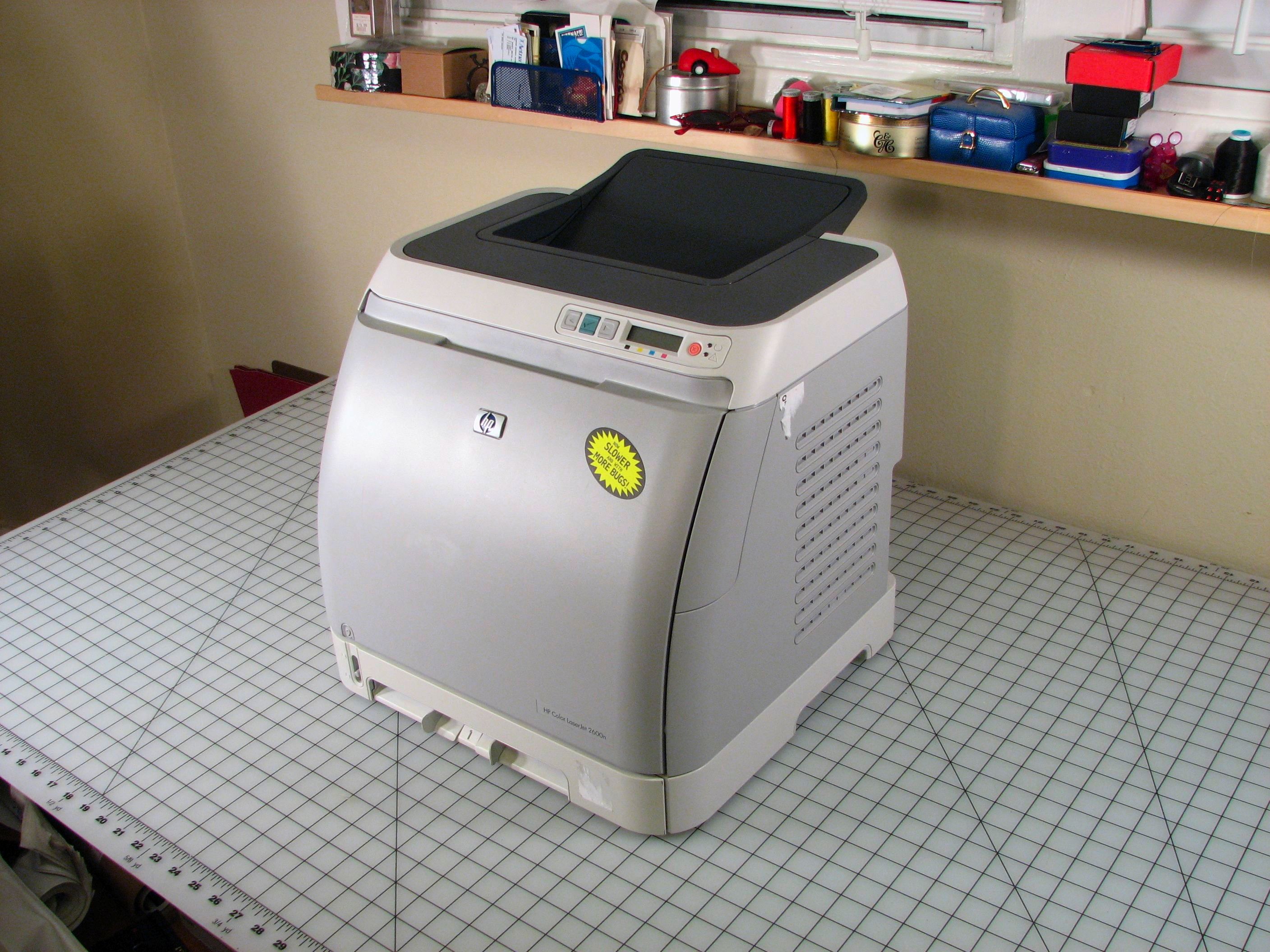
On the bench today: an HP Color LaserJet 2600n, a modern compact color laser printer.
This printer is a curious beast. To an end user, how it works is pretty straightforward– you plug in an ethernet or USB cable and install the driver. But it’s really a technological marvel– a remarkably compact and precise “black box” that wields lasers, high voltage, motors, heaters, sensors, gears, and esoteric electromagnetic properties of specially formulated powders to produce photorealistic images on a sheet of paper.
From an economic perspective, it’s even more of a mystery. Brand new printers like this one are often on sale for about $300, complete with a set of full toner cartridges. You can also buy a set of replacement toner cartridges for it, for about $330. Thus from a crude economic perspective (that is, ignoring the extreme environmental irresponsibility of the remainder of this thought) it could possibly make more sense to just go ahead and buy a new printer when you run out of ink. Certainly, loss-leader printers have been the standard for some time in low end inkjets– is that what’s going on here, only at a higher scale? Maybe, but it’s not an open-and-shut case: the initial set of toner cartridges will last for years for infrequent home users, so it’s hard to imagine that HP would make money on every sale if they had to rely on many cartridges to be sold for every printer.
The printer on the bench today has served us well, but its time has finally come. In taking it apart, we’ll take a look at the design and see what interesting components are inside that might be reusable for other projects. (Hint: lots.) We’ll also see some of the very interesting guts in much more detail than your average teardown. We set out to make a photo essay of this, but at well over 200 photos (exchanged at the standard rate) this actually turns out to be less of an essay than an epic novel.
On this page we’ll show off some of the more interesting photos from the teardown– obviously we don’t want to put all of them up here, so it’s thumbnails only as we go. The entire set of 200+ full-resolution photos can be found here in a flickr set. (And of course, you can click the individual photos for other sizes.)
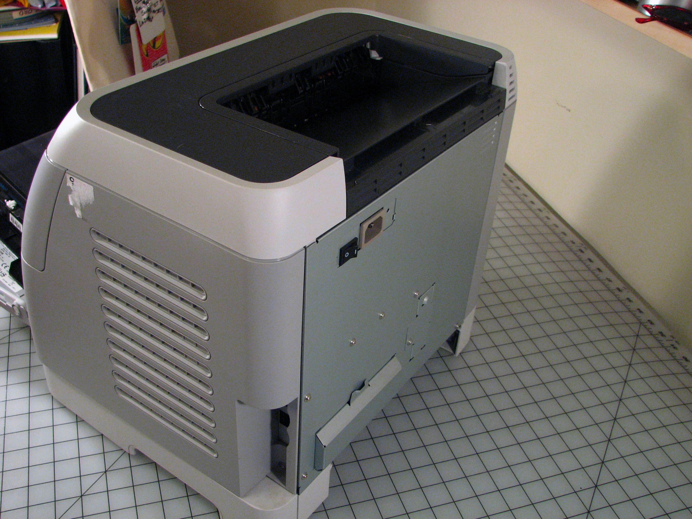
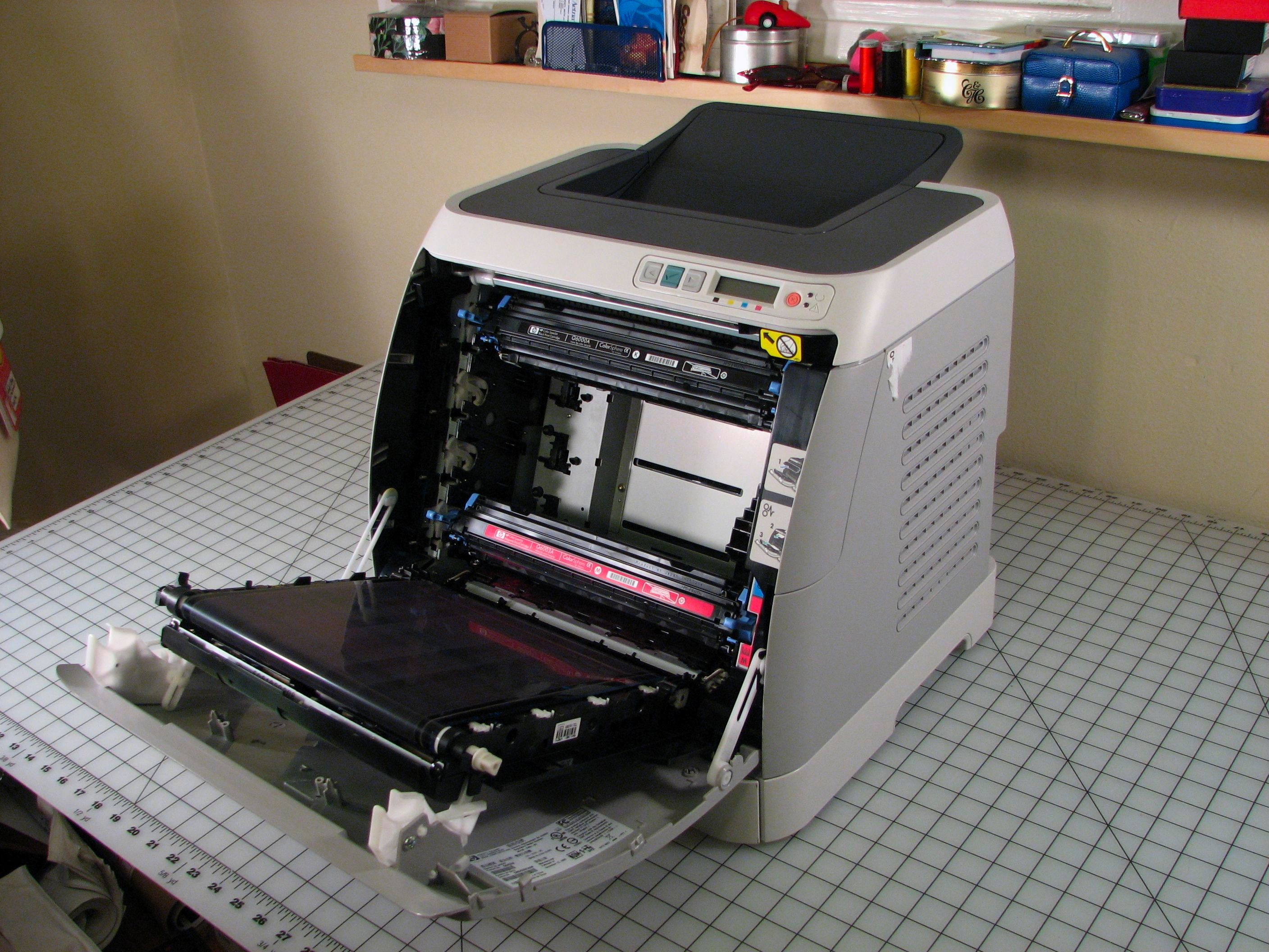
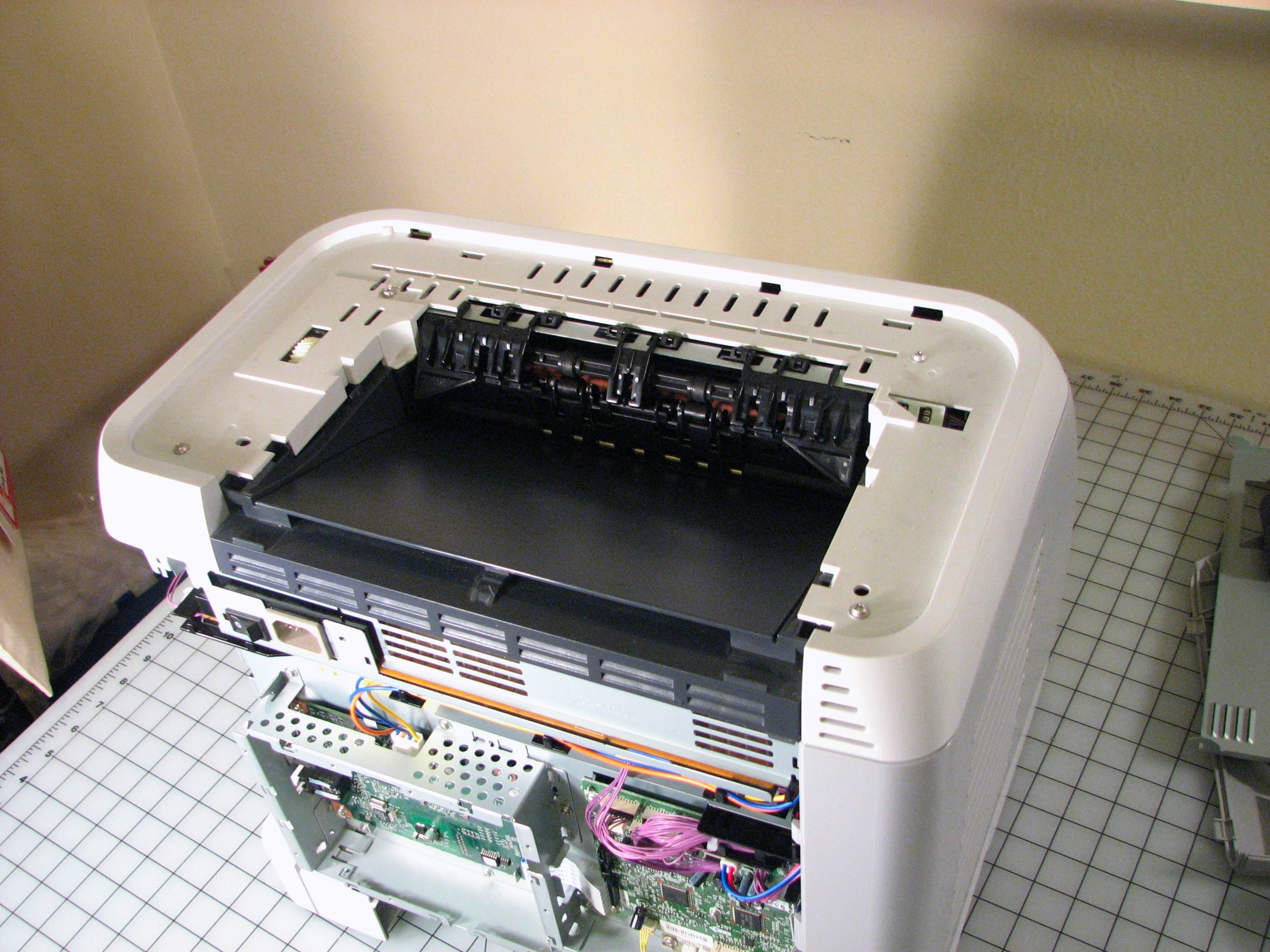
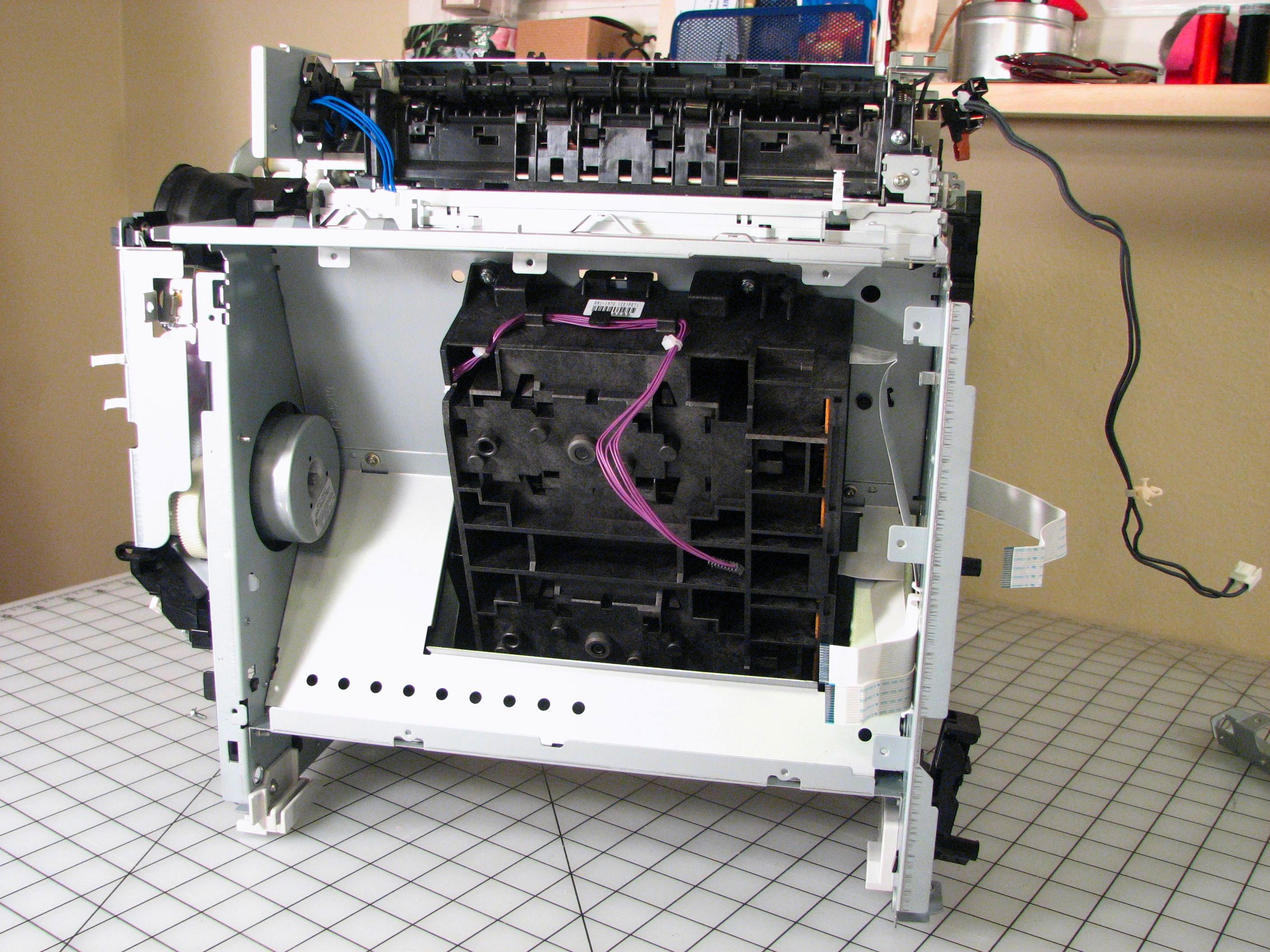
First, here’s what you see without taking anything apart. Just open the front door, pull out the toner cartridges, and take a look at the back. The back plate is sheet metal, held on by phillips head screws. One truly remarkable thing about this design is that you only need a single phillips head screwdriver to completely disassemble it. Everything else is held together with little snap tabs that can be unhooked. (Okay, some of the tabs require a small tool like a flathead screwdriver to disengage.)
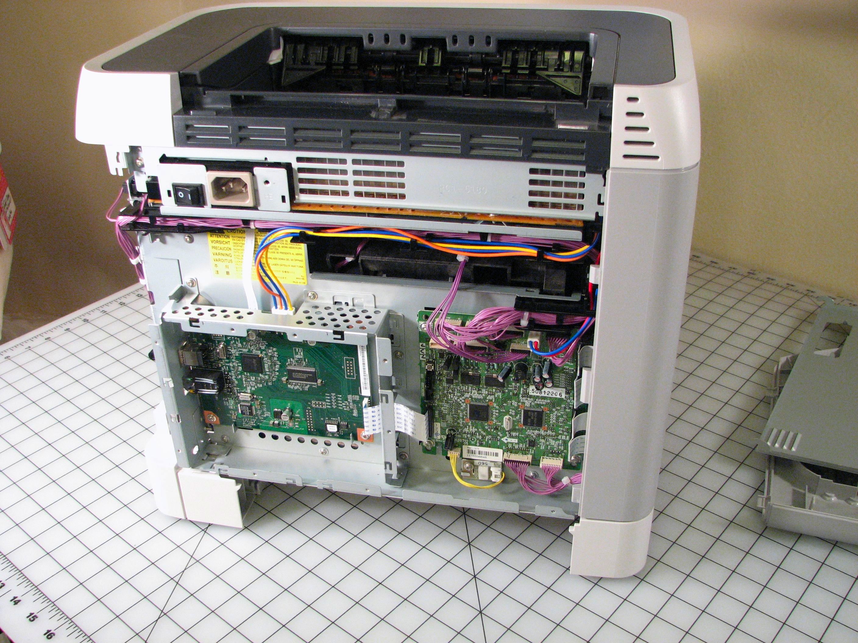
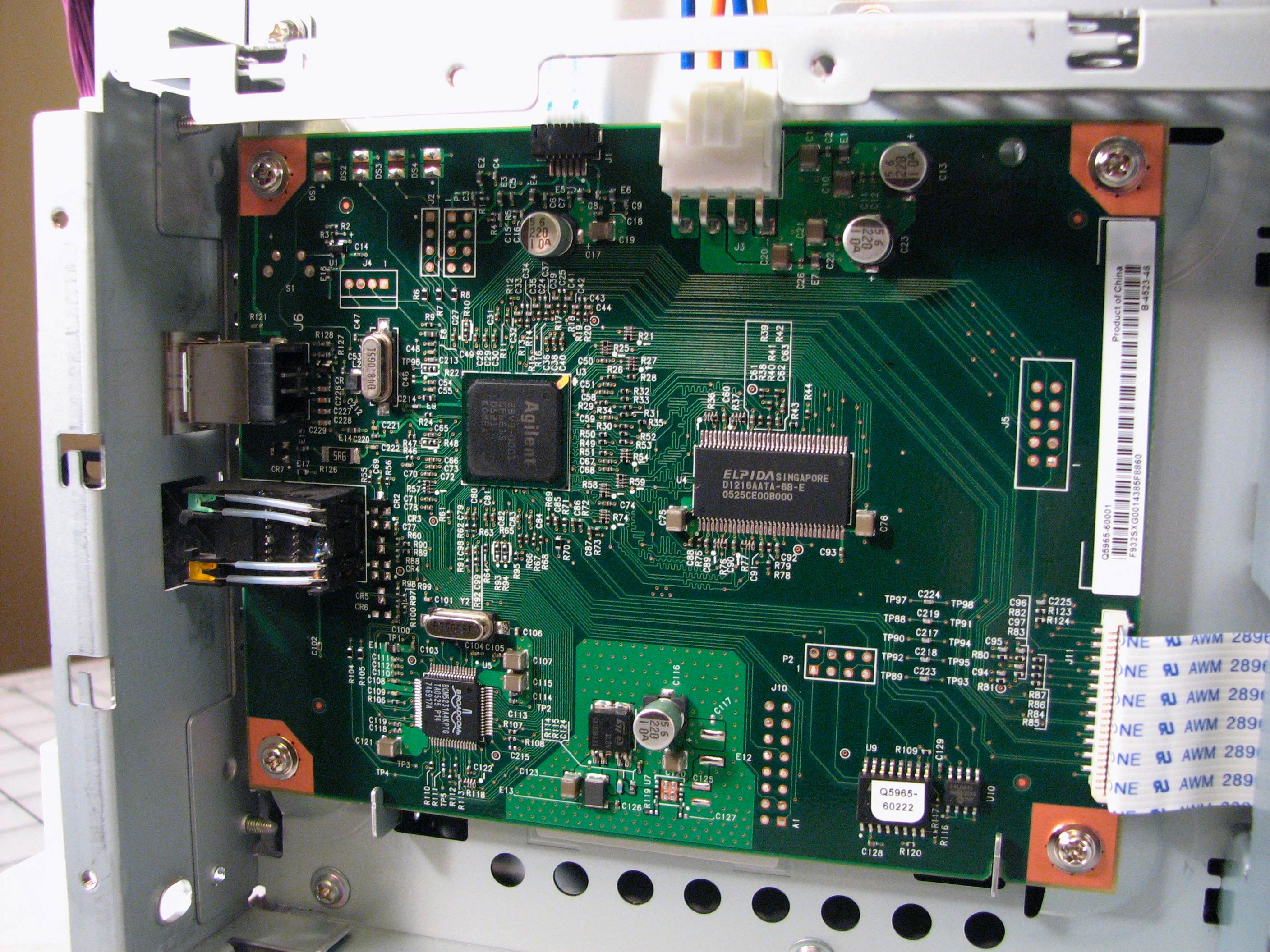
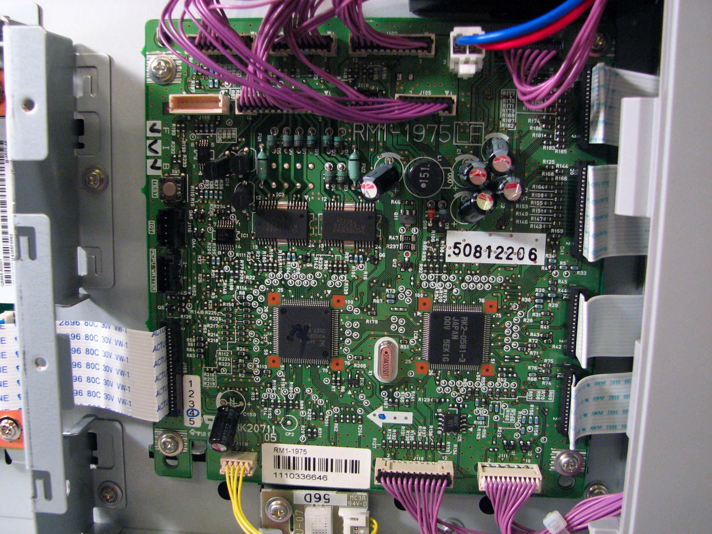
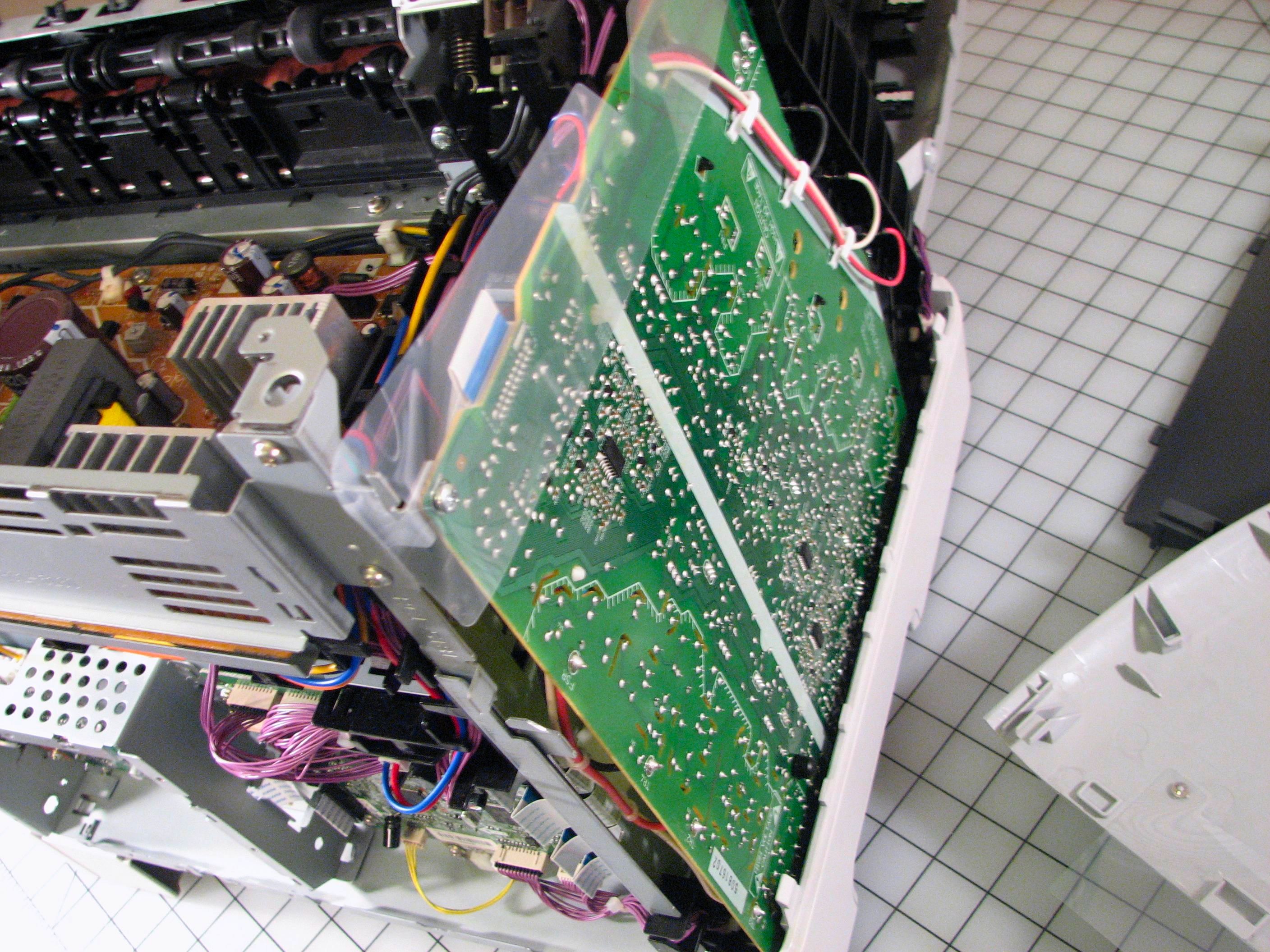
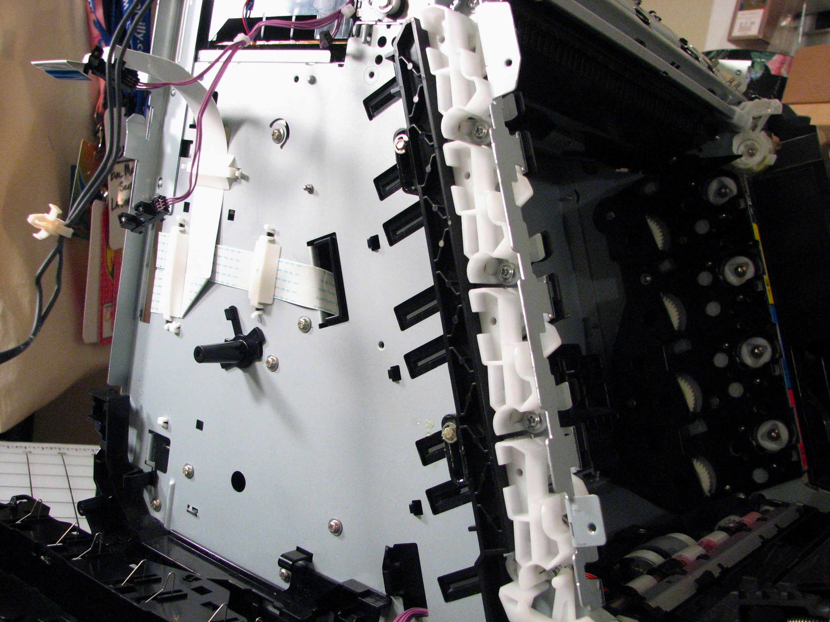
The right cover comes off, and then we unscrew the back panel. There are two big circuit boards in the back panel. As Bunnie has written about, there are two circuit boards back there that control the communications with the outside world (left) and running the rest of the printer (right), including motor control.
If you look very closely below the circuit board on the right, you might see a tiny little third circuit board:
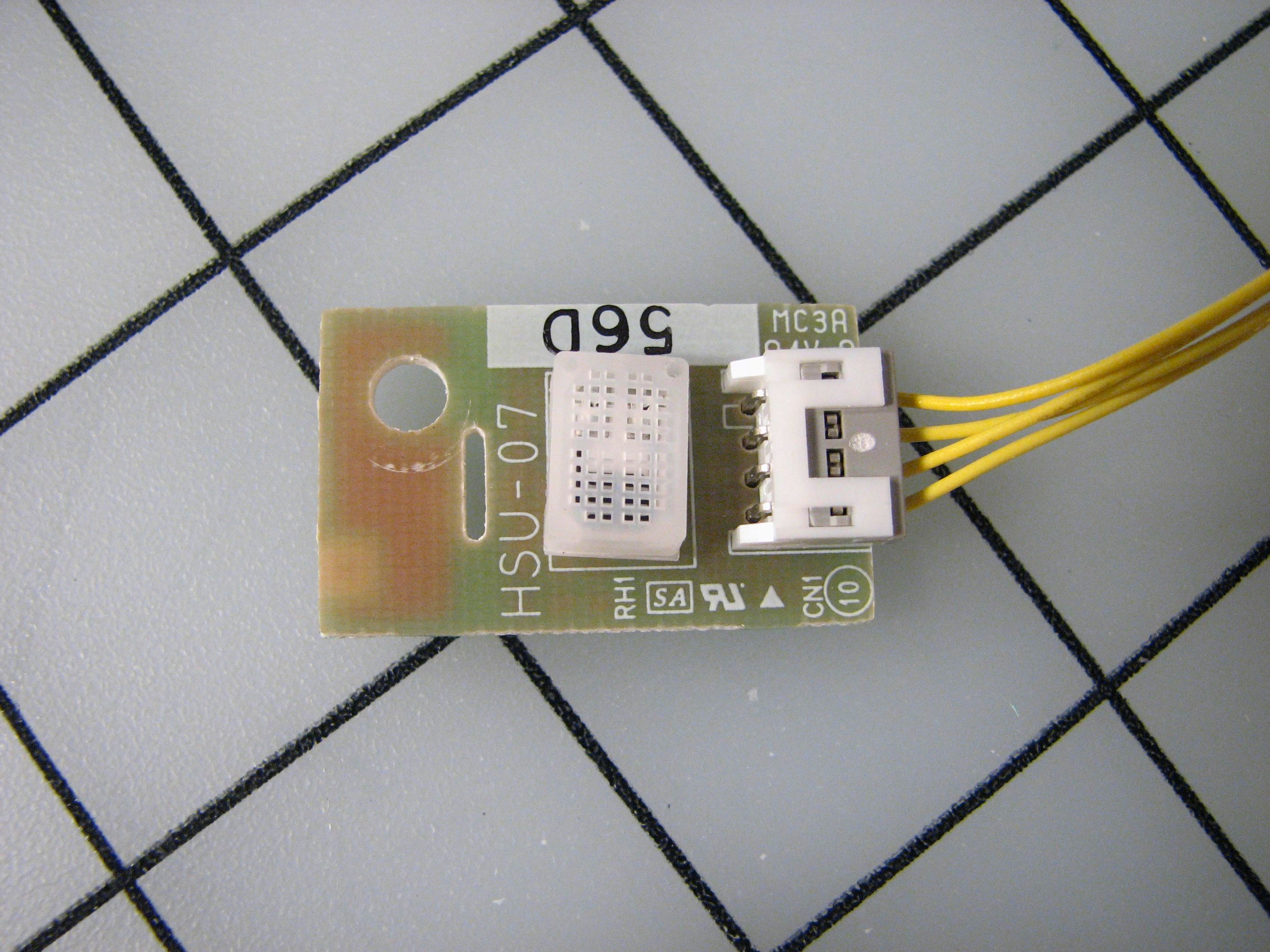
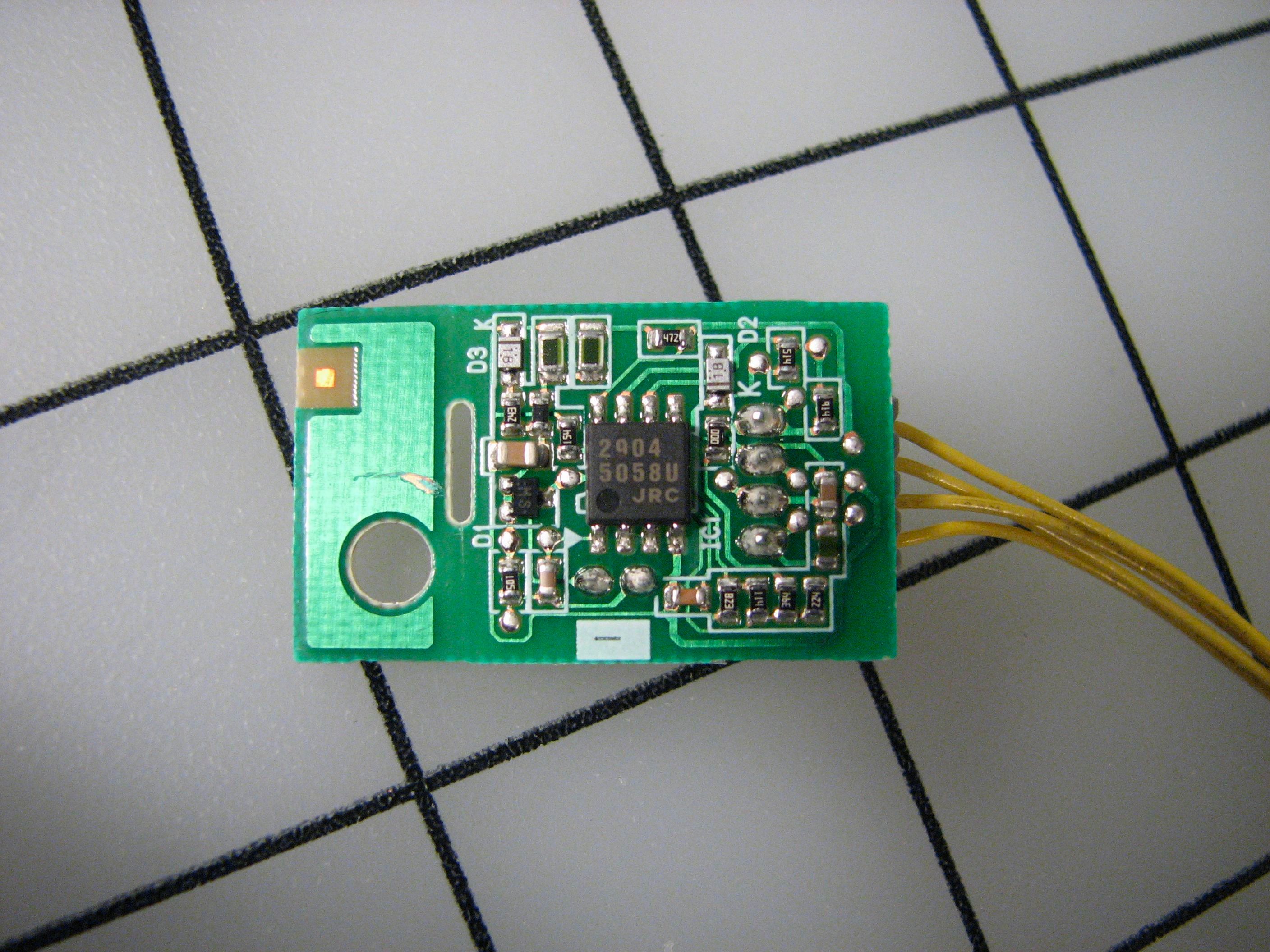
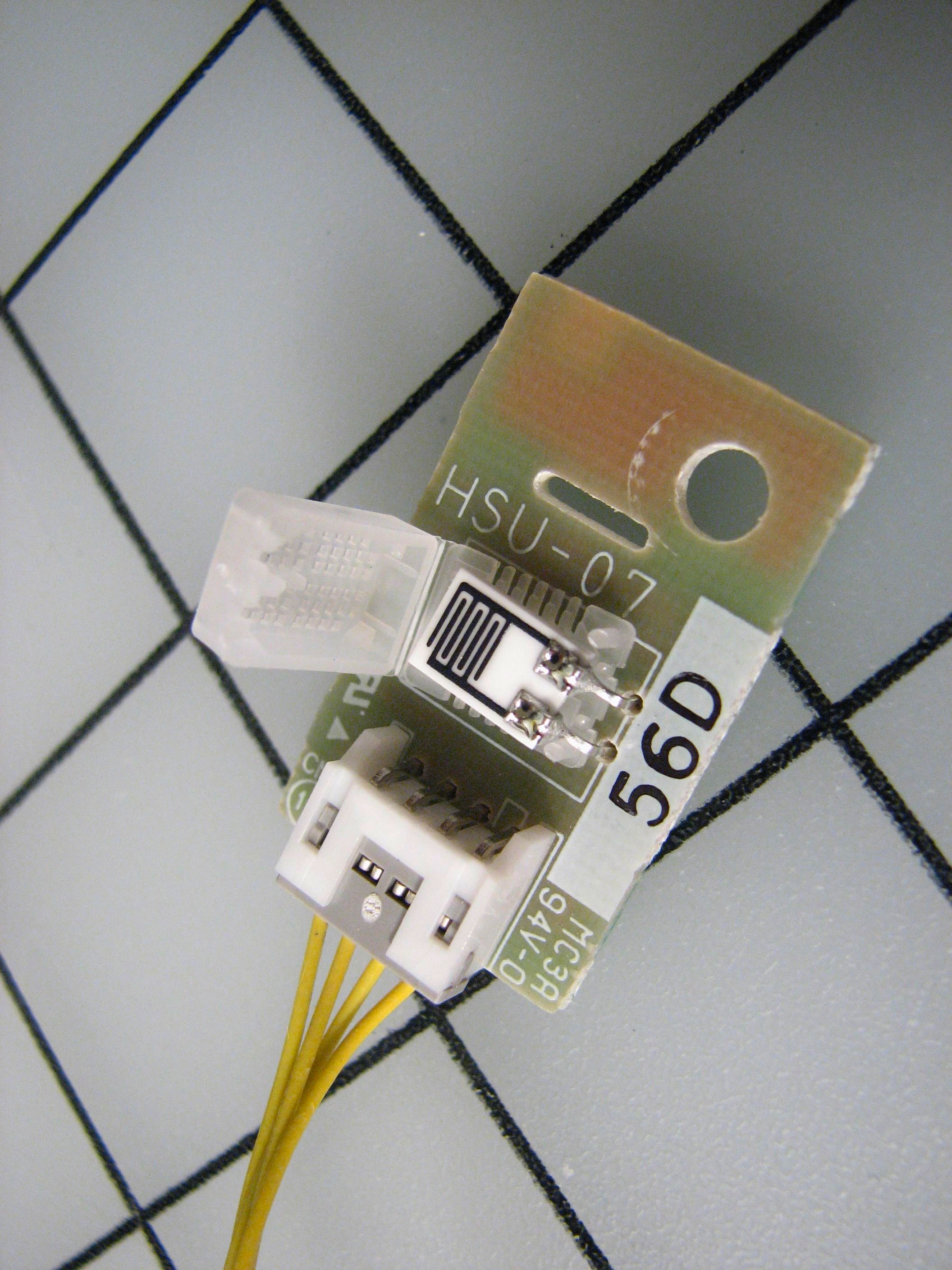
This board contains a humidity sensor– interesting little component. Apparently printing conditions depend strongly on humidity, for reasons of toner behavior and the hygroscopic nature of paper. The best information that I could find on the subject is this patent about using temperature and humidity data to stabilize image quality under varying conditions.
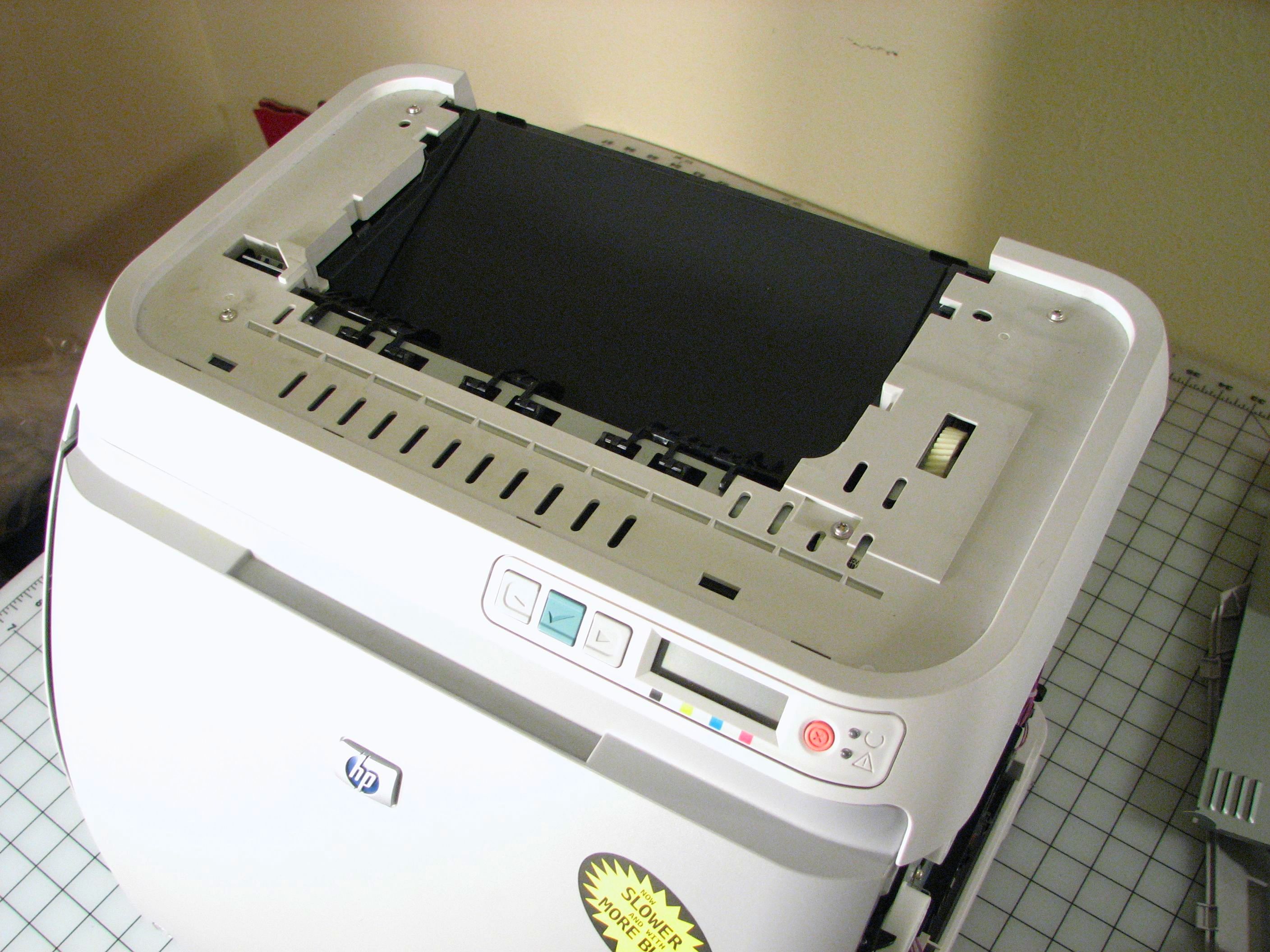
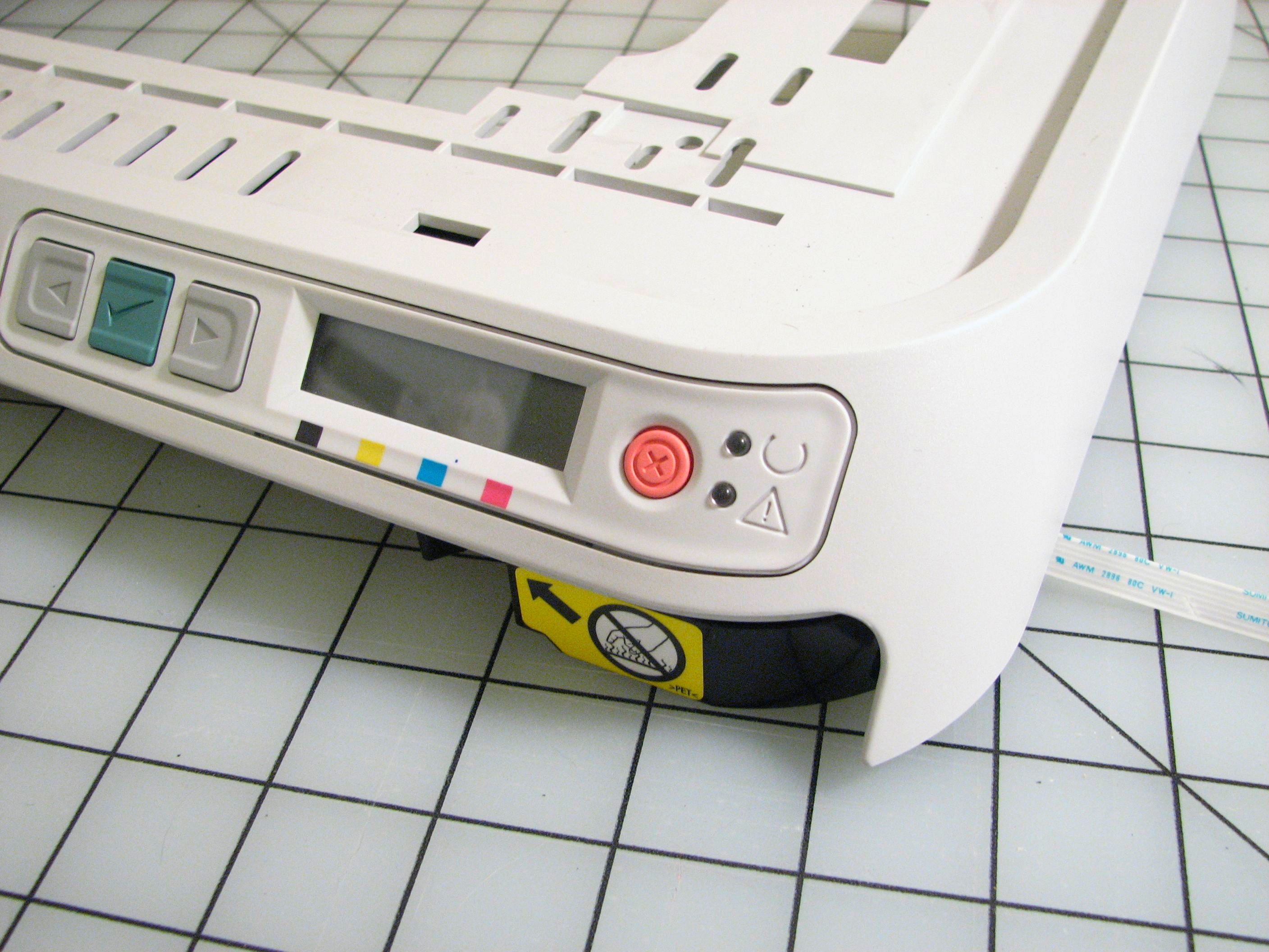
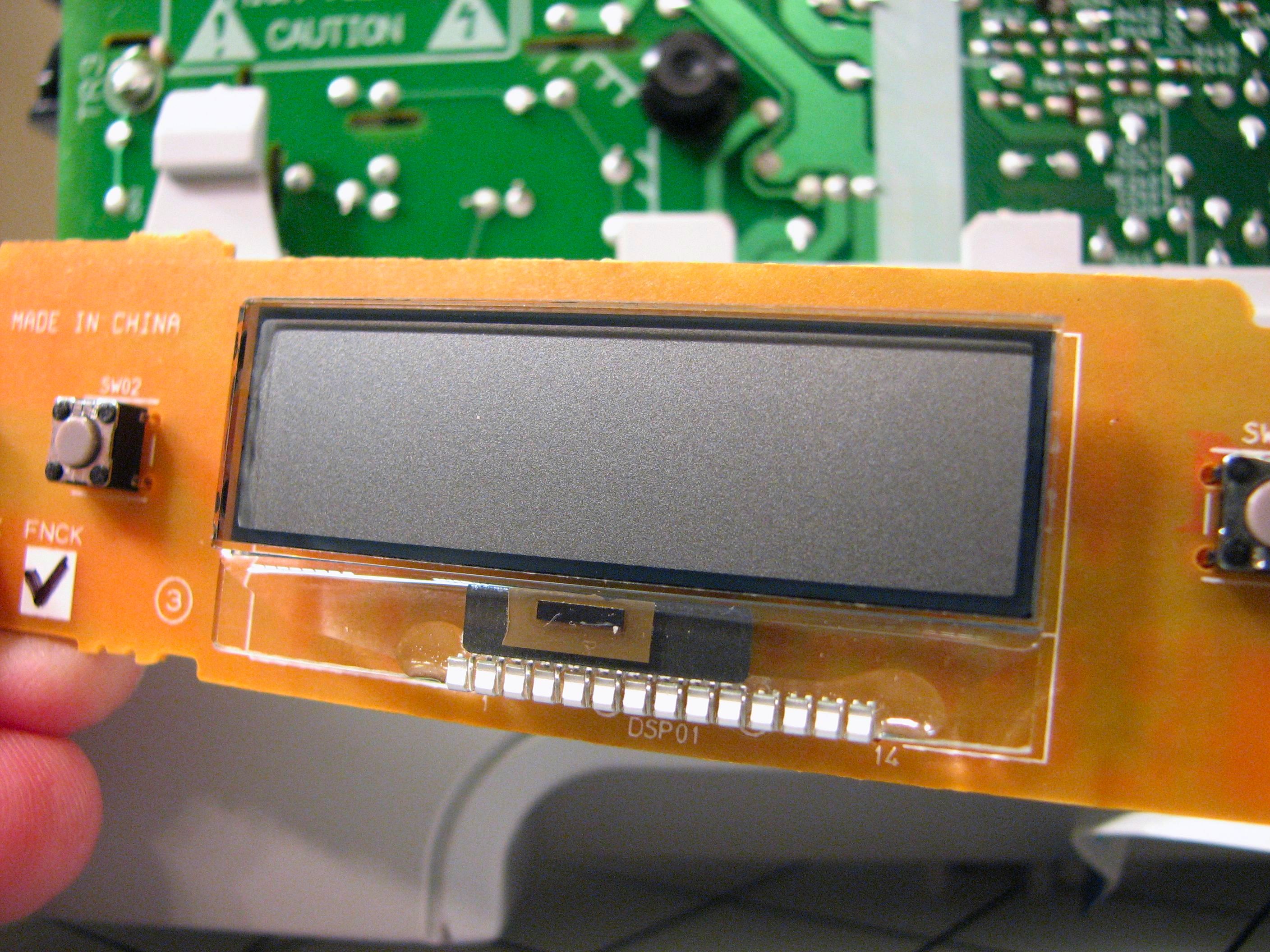
Remove the top lid, including the LCD display interface section.
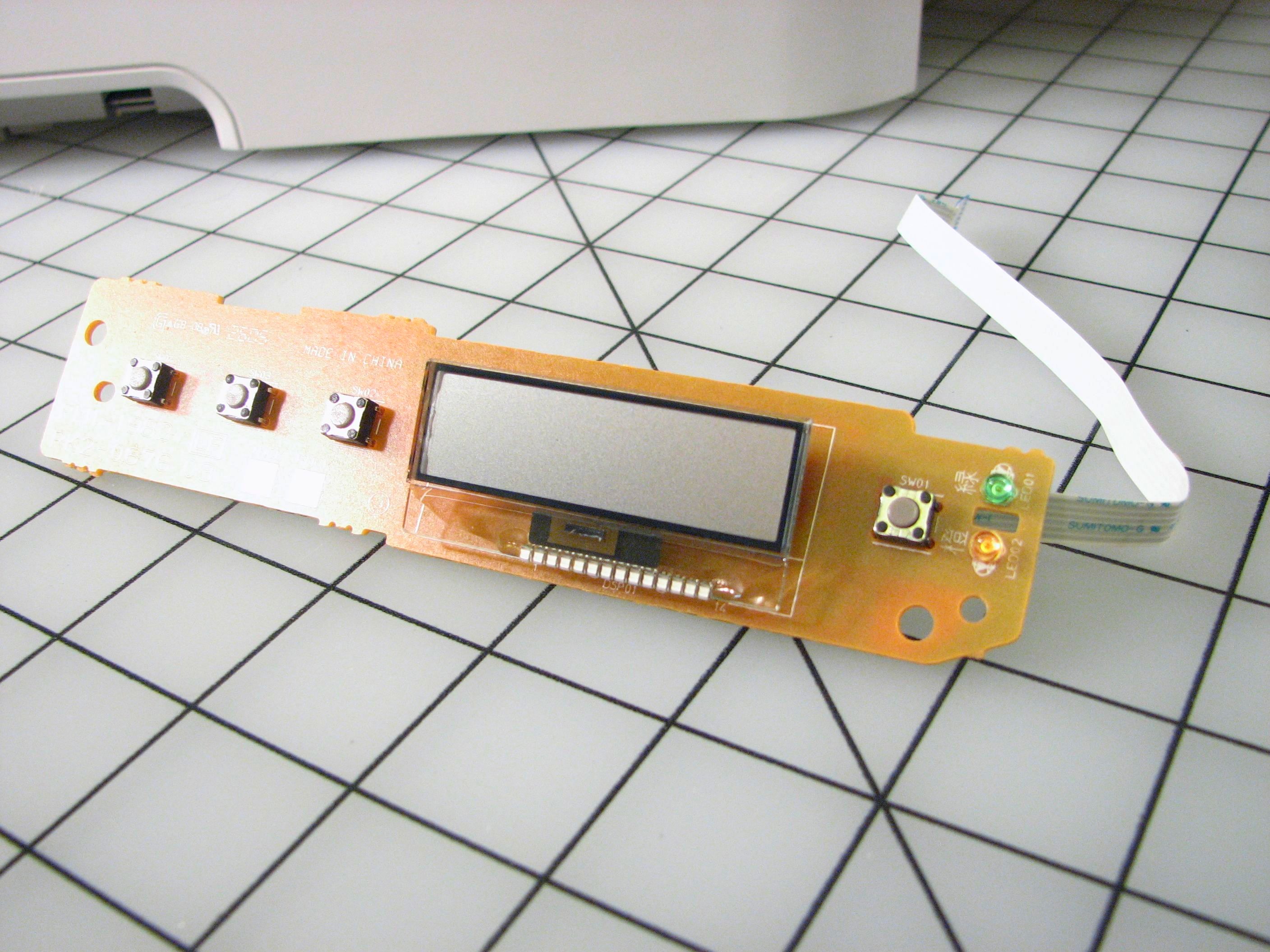
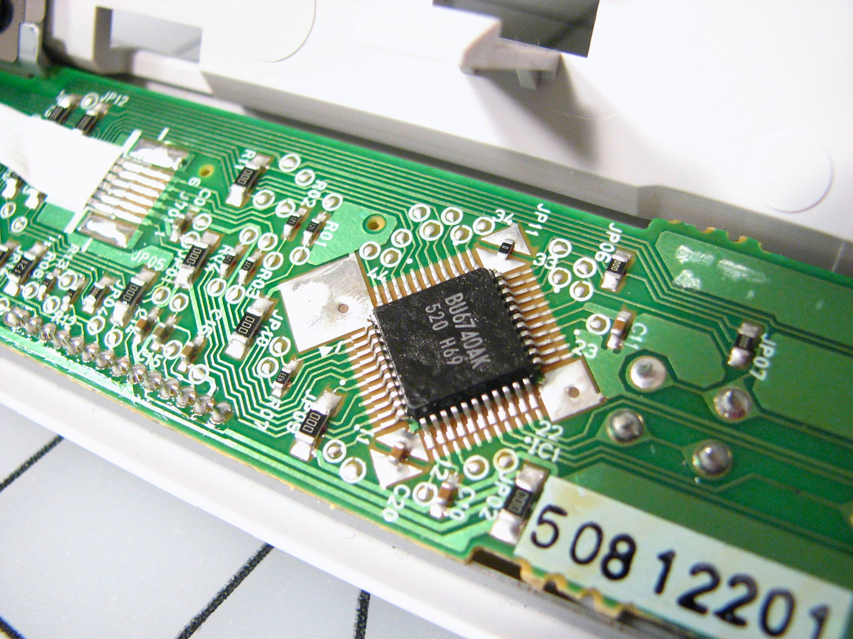
The LCD sits on a small circuit board with the buttons and LEDs. The chip on the back side of this single-layer printed circuit board is an LCD controller.
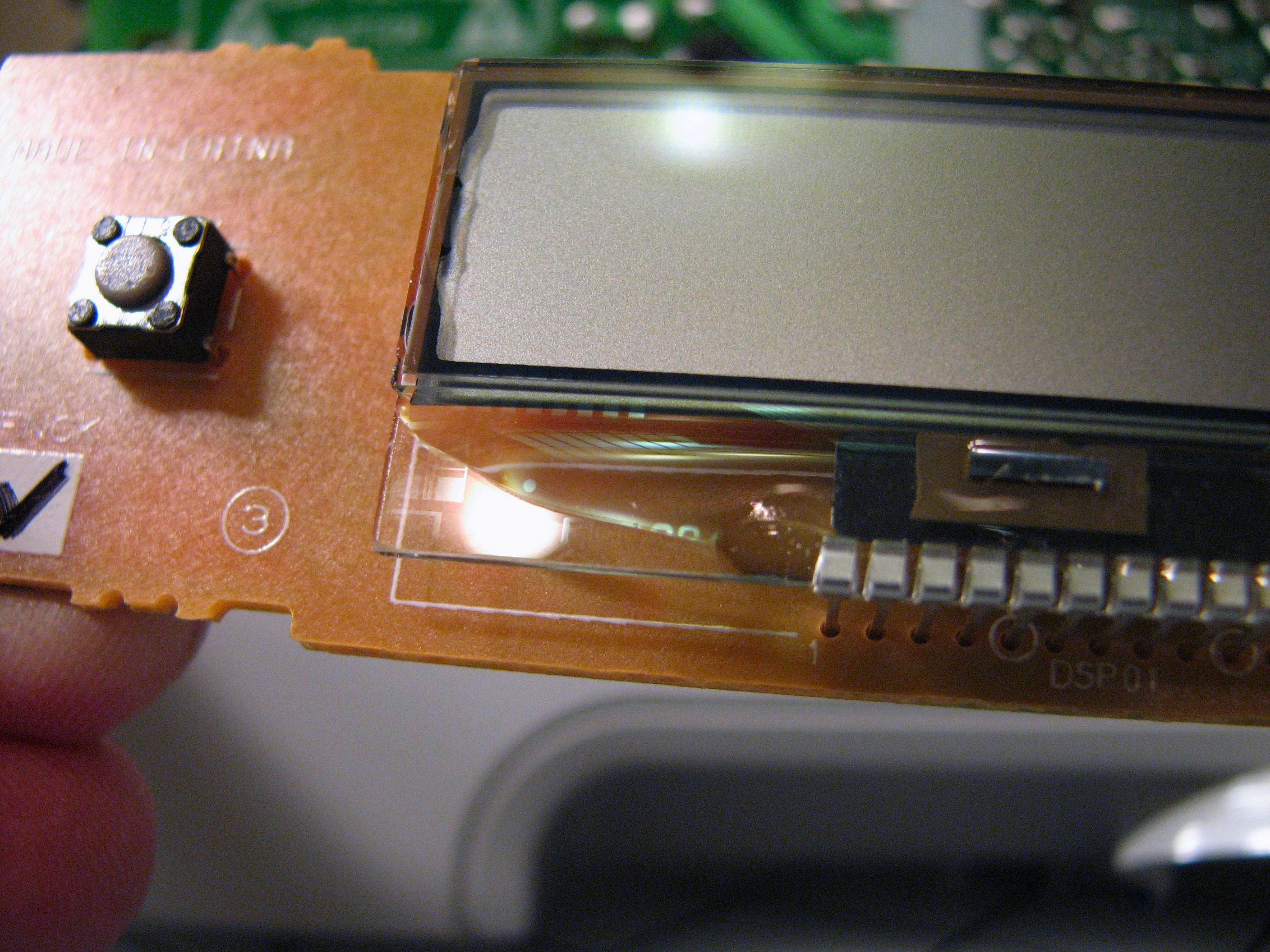
The LCD itself is a fantastic little unit with transparent circuit traces that are only visible if you hold it just so. Wow. This is a big step up from the zebra-strip used on the pedometer that we took apart.
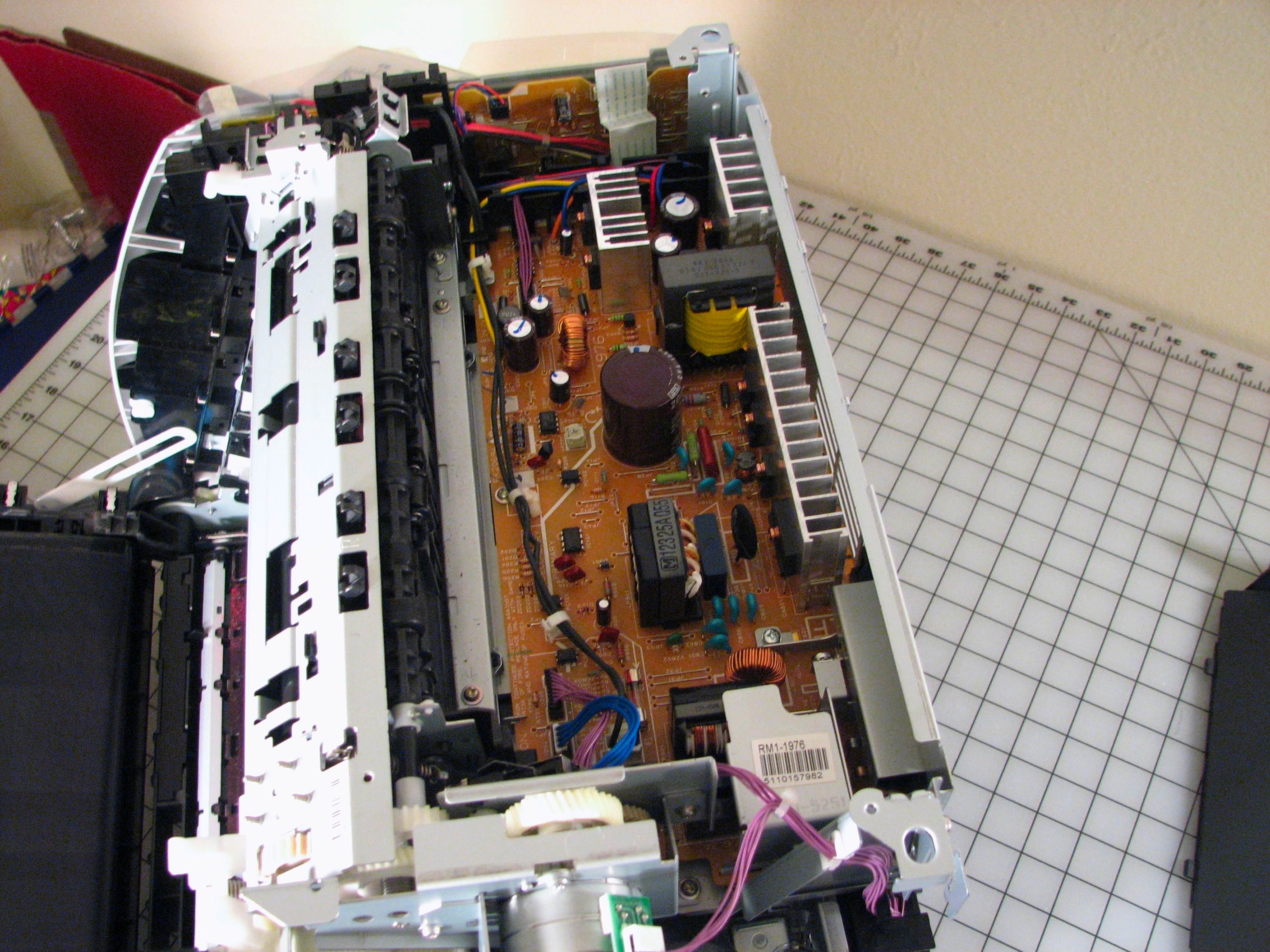
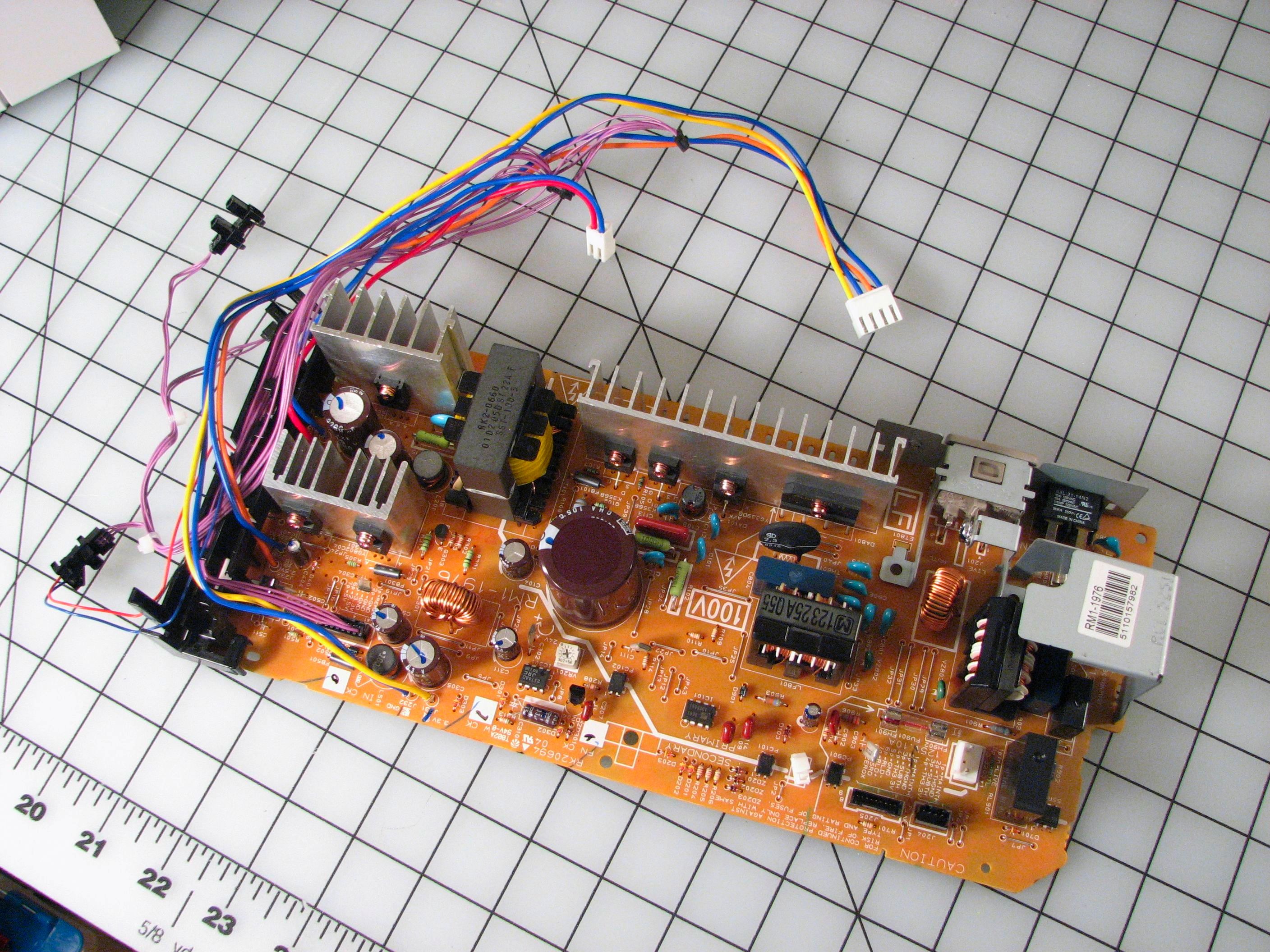
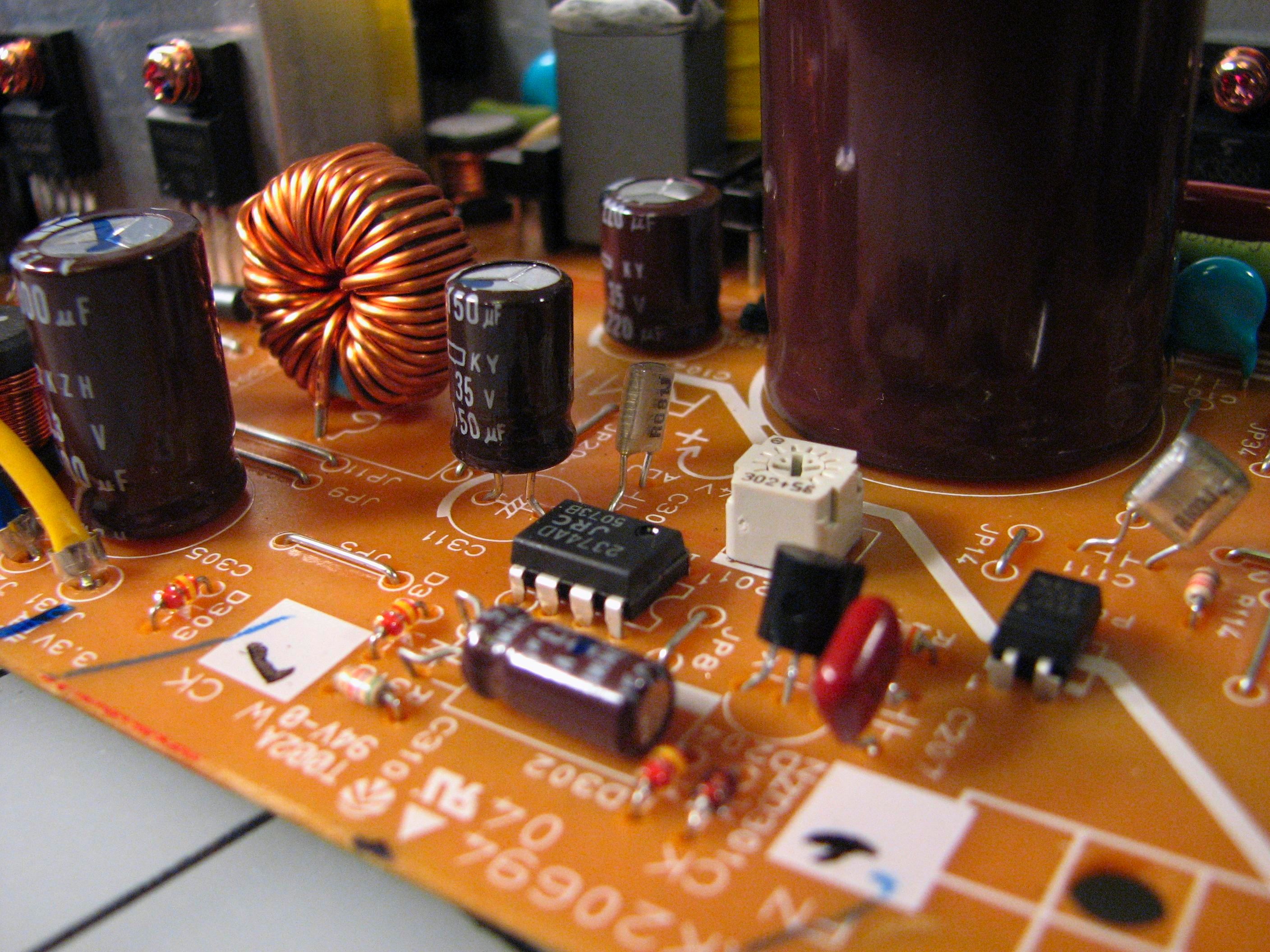
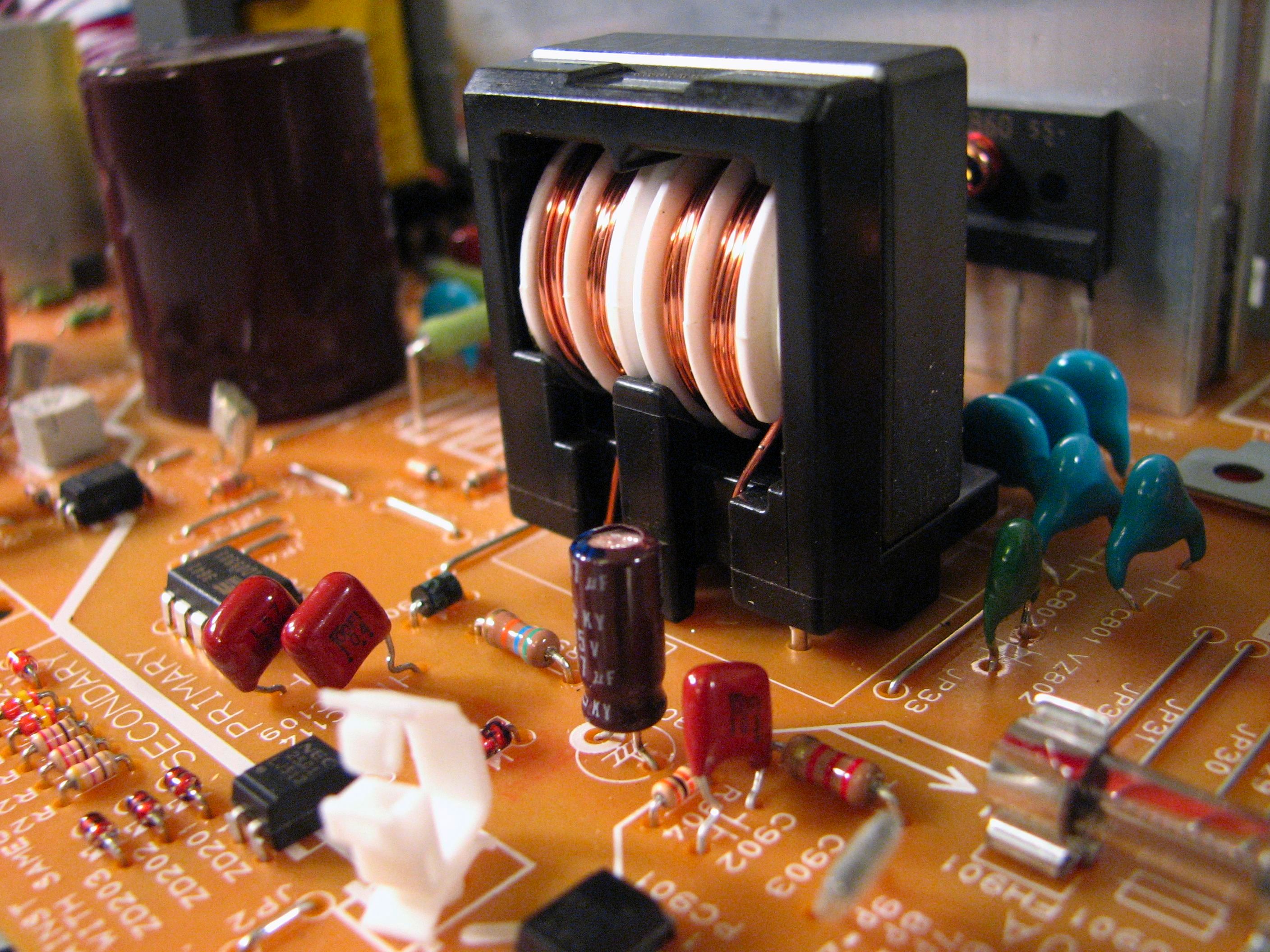
Removing the top plate with the LCD exposes this “analog” circuit board. This is the power supply section, where you can find the power entry jack, power switch, transformers, transistors, diodes, capacitors, fuses, and heat sinks. If you look closely in the upper left photo, you can see two big fat high-current wires that go of to the fuser.
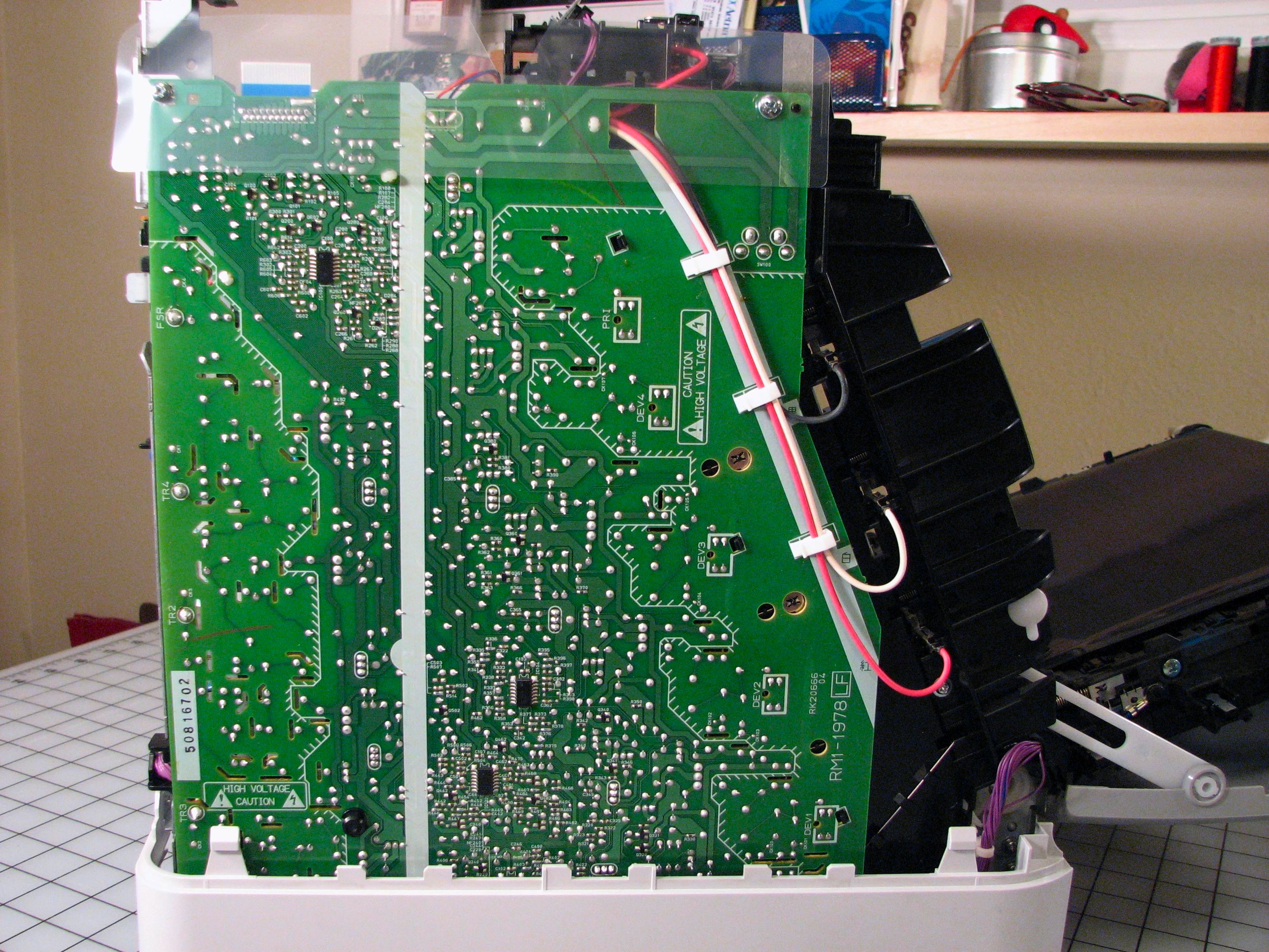
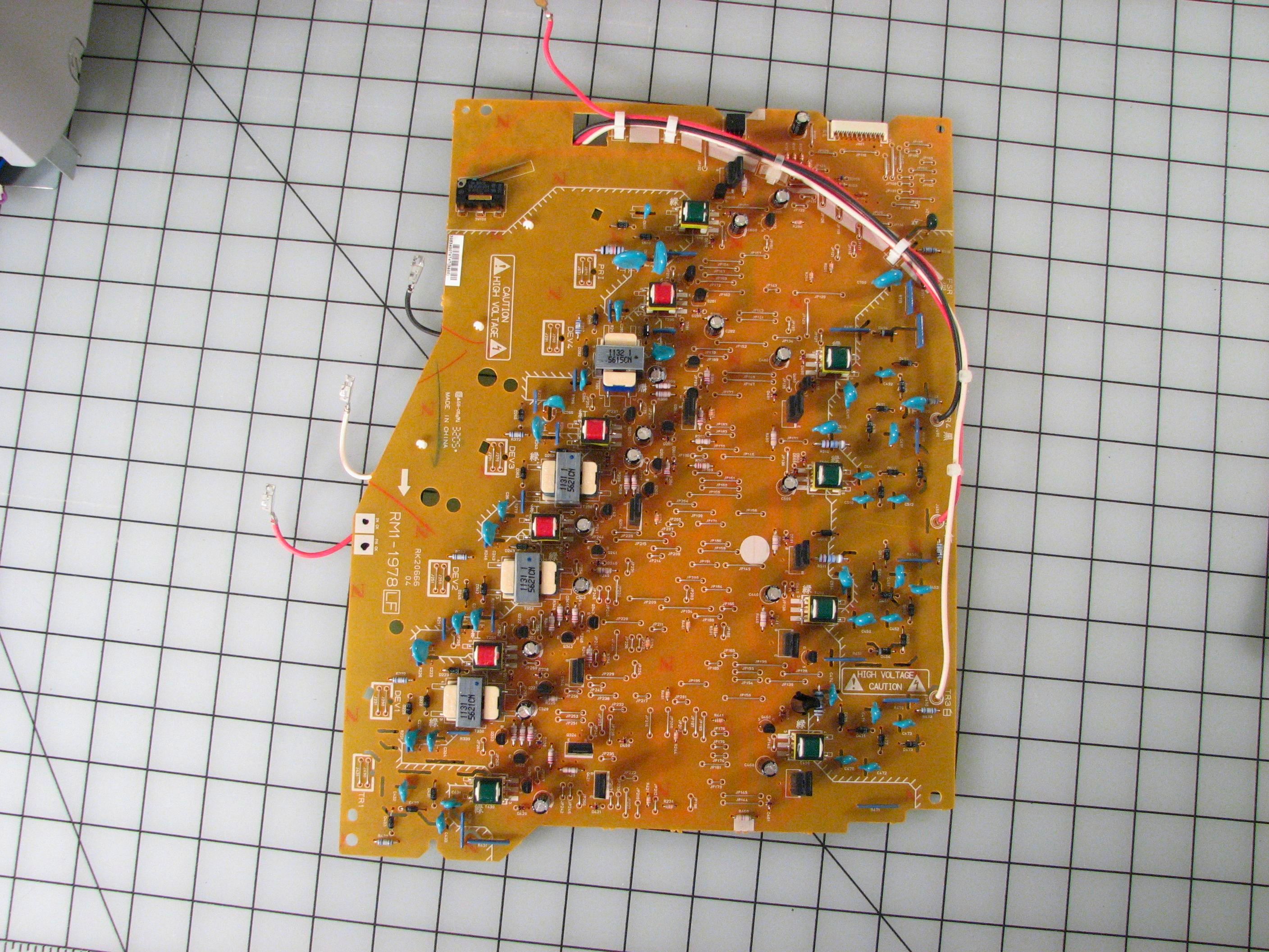
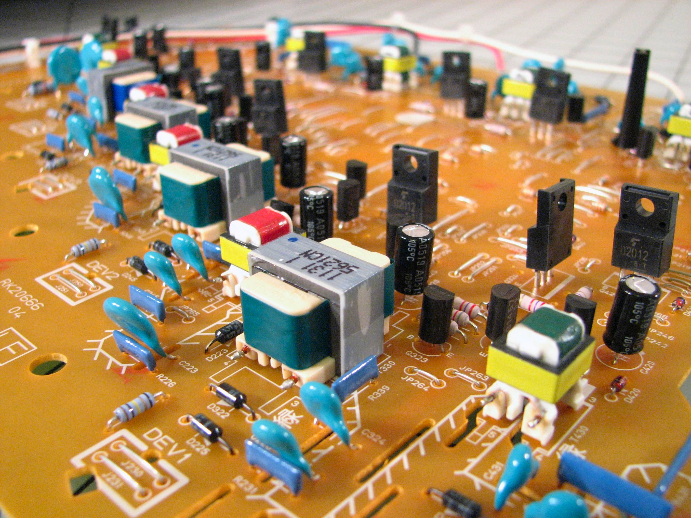
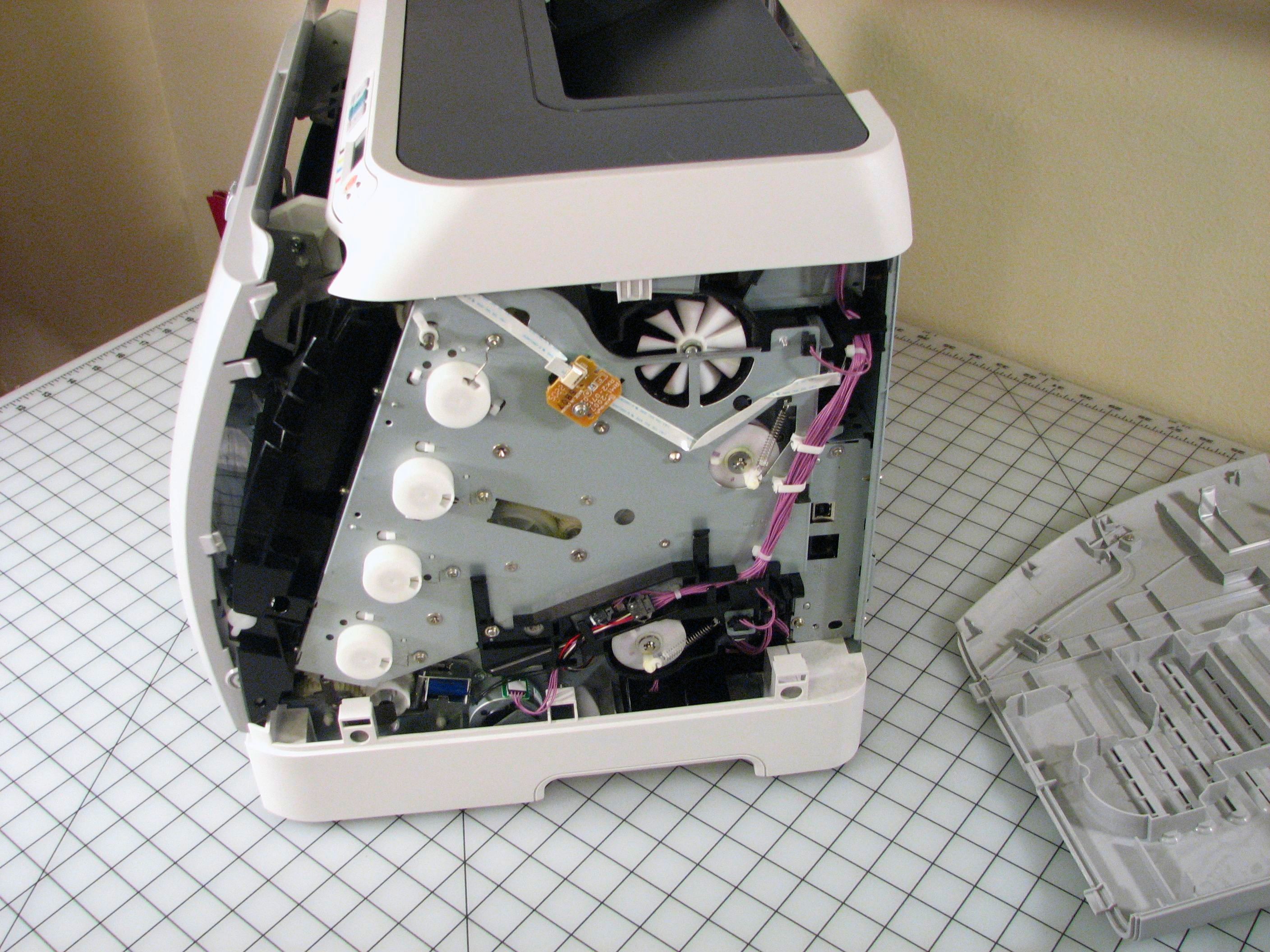
Underneath the plastic fairing on the left side of the printer is a monster of a circuit board. It’s a single-sided board that is almost as big as the printer itself. The middle portion is full of small surface mount components, while the outer few inches on both sides is filled up (on the opposite side) with carefully spaced apart high voltage components. There is a treasure trove of high voltage goodies, including capacitors, transformers, diodes, and resistors. The capacitors that I noticed are rated up to 6 kV. Note also the slots in the circuit board to increase resistance between isolated areas. (High voltage is used in a laser printer to create electrostatic charges that determine where toner does– or does not– stick.)
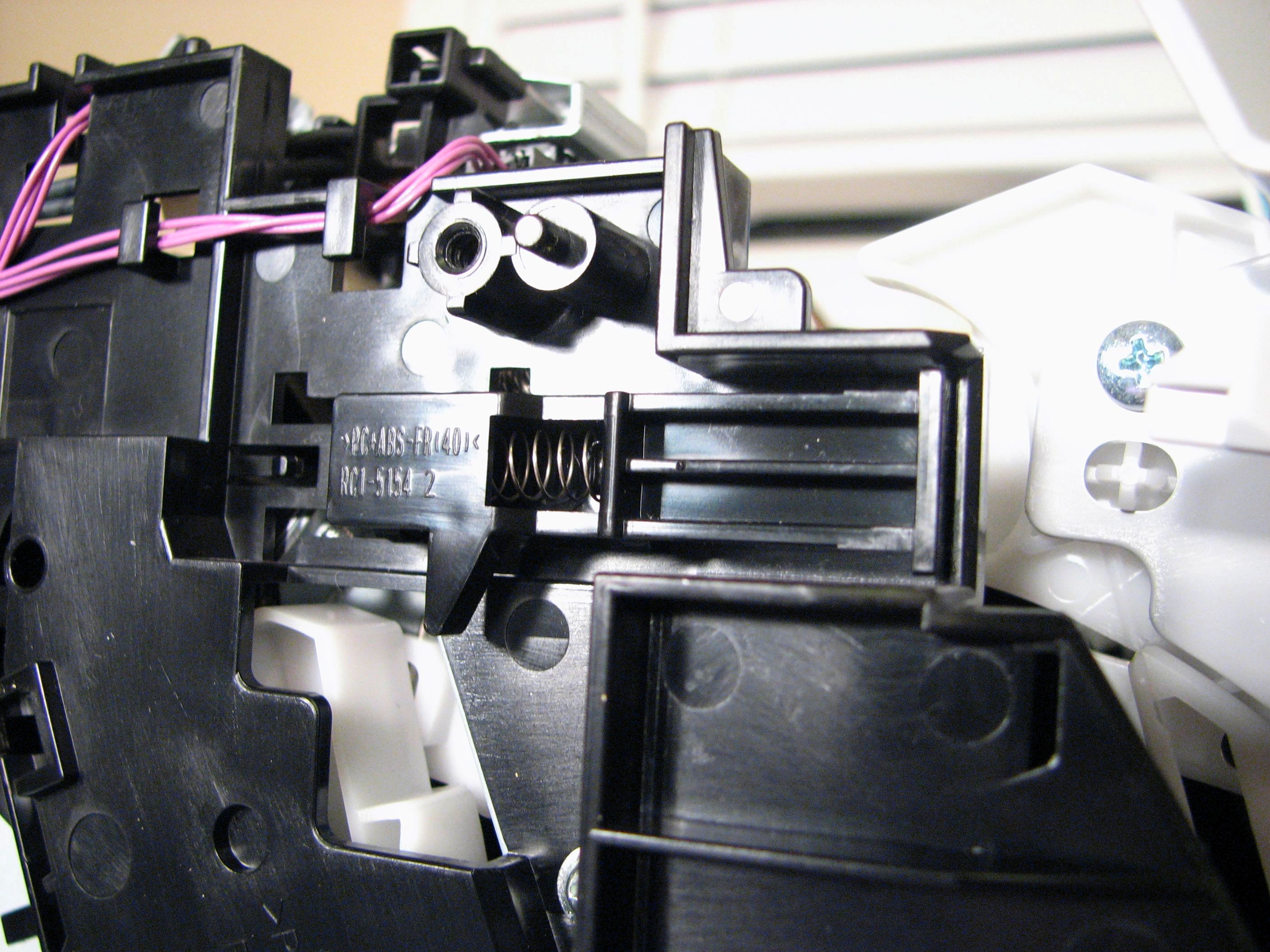
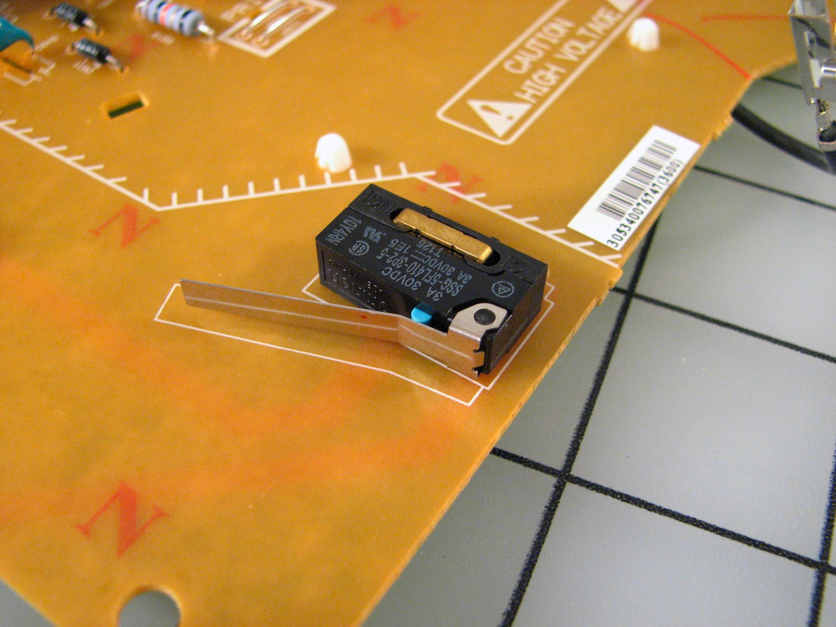
Isn’t all that high voltage dangerous? Well, yeah. When you close the front door of the printer, it pushes a little spring-loaded lever (left) that in turn pushes a microswitch (right) on the high-voltage circuit board that tells the printer that it’s okay. Safety first! (Unless you want to hack it or play with the high voltage and kill yourself– now you know how to defeat the interlock.)
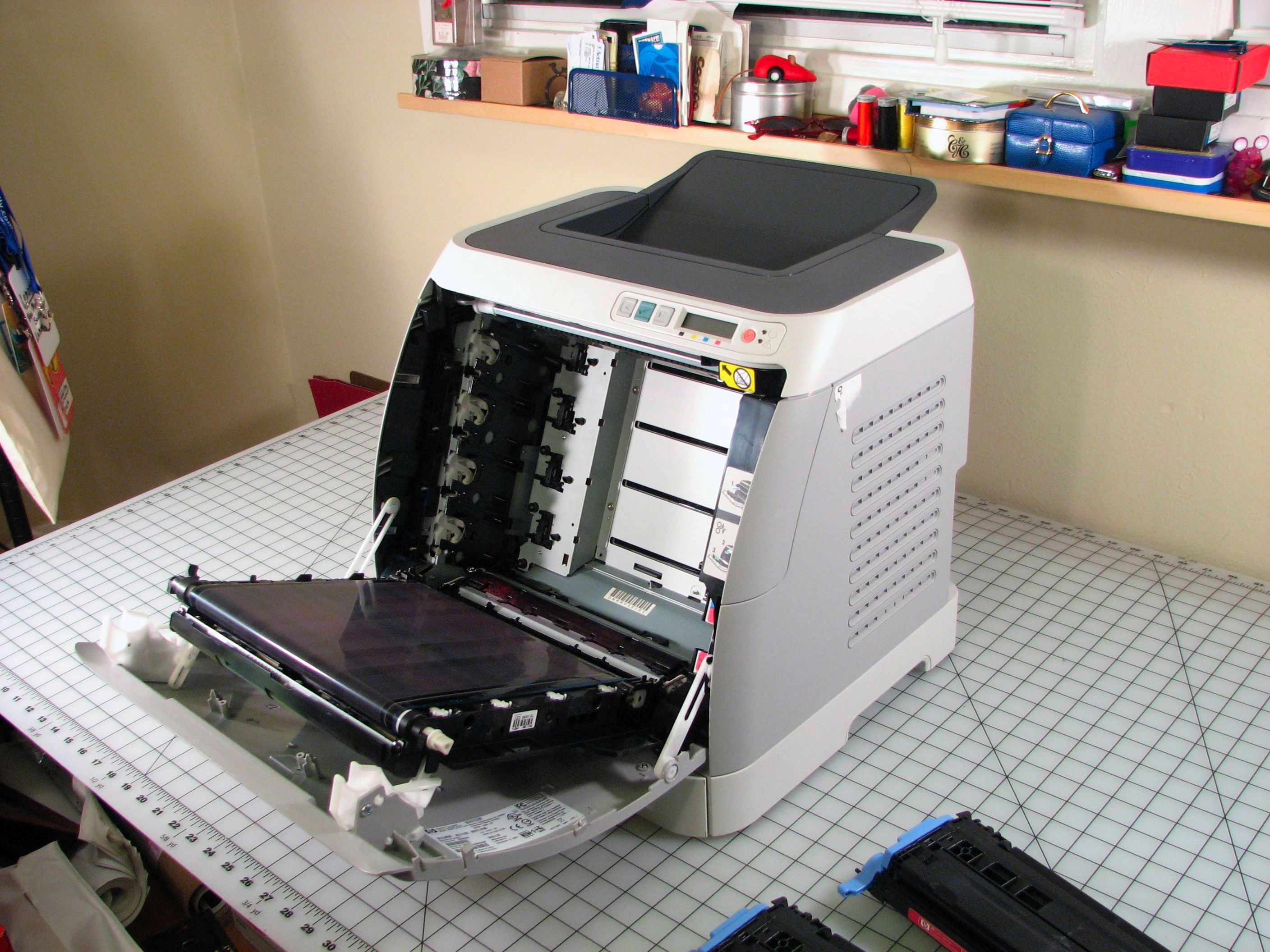
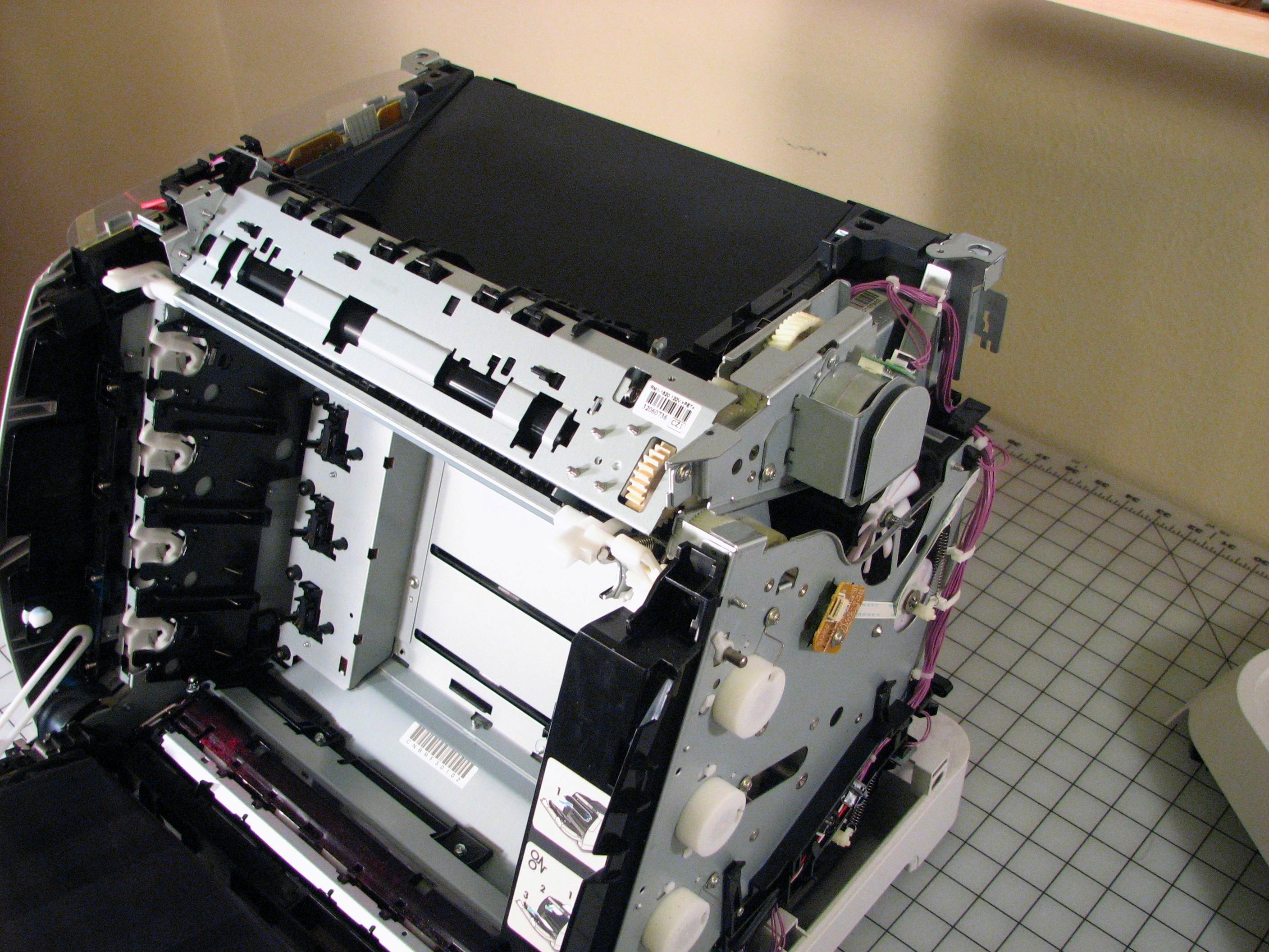
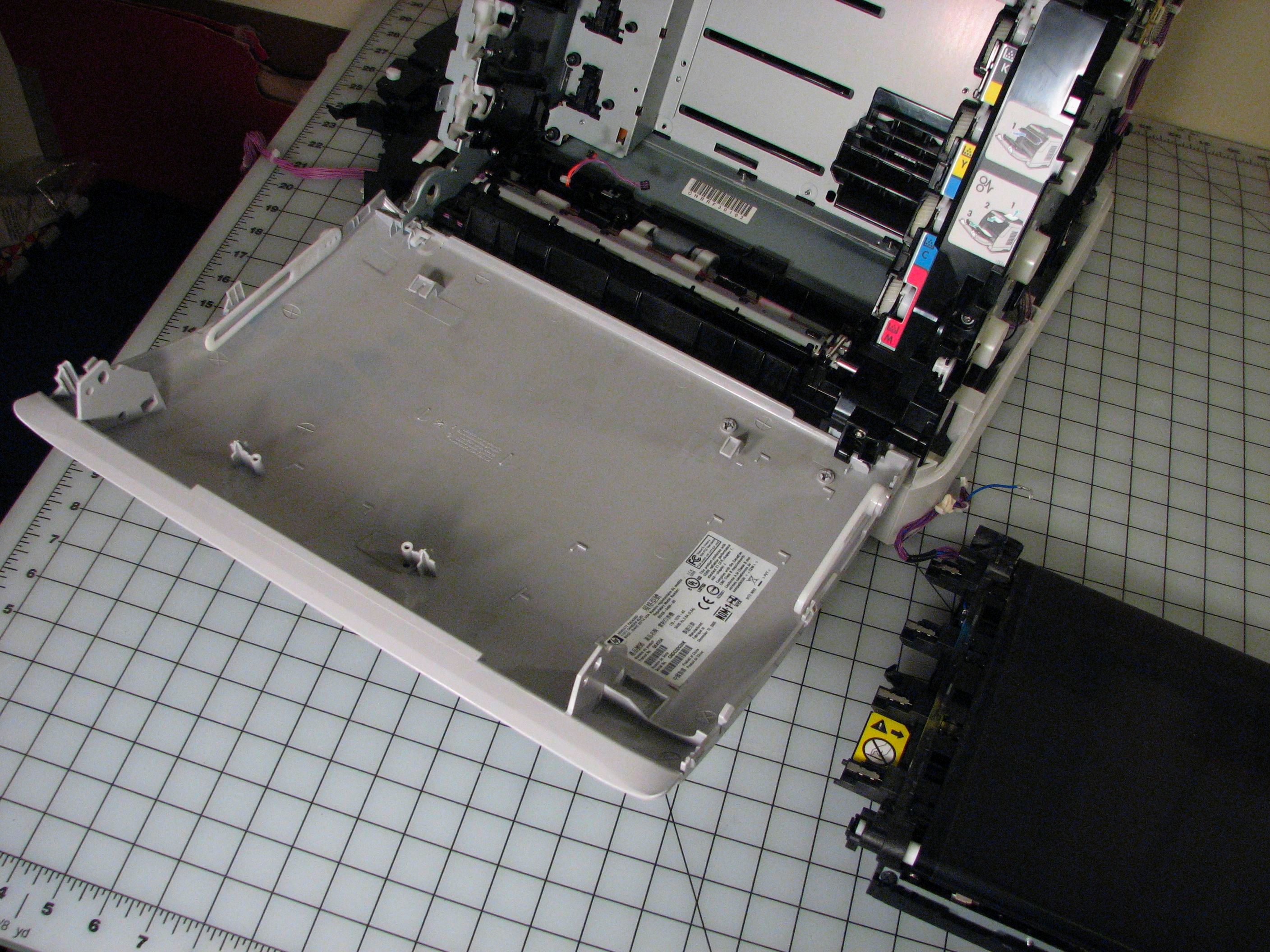
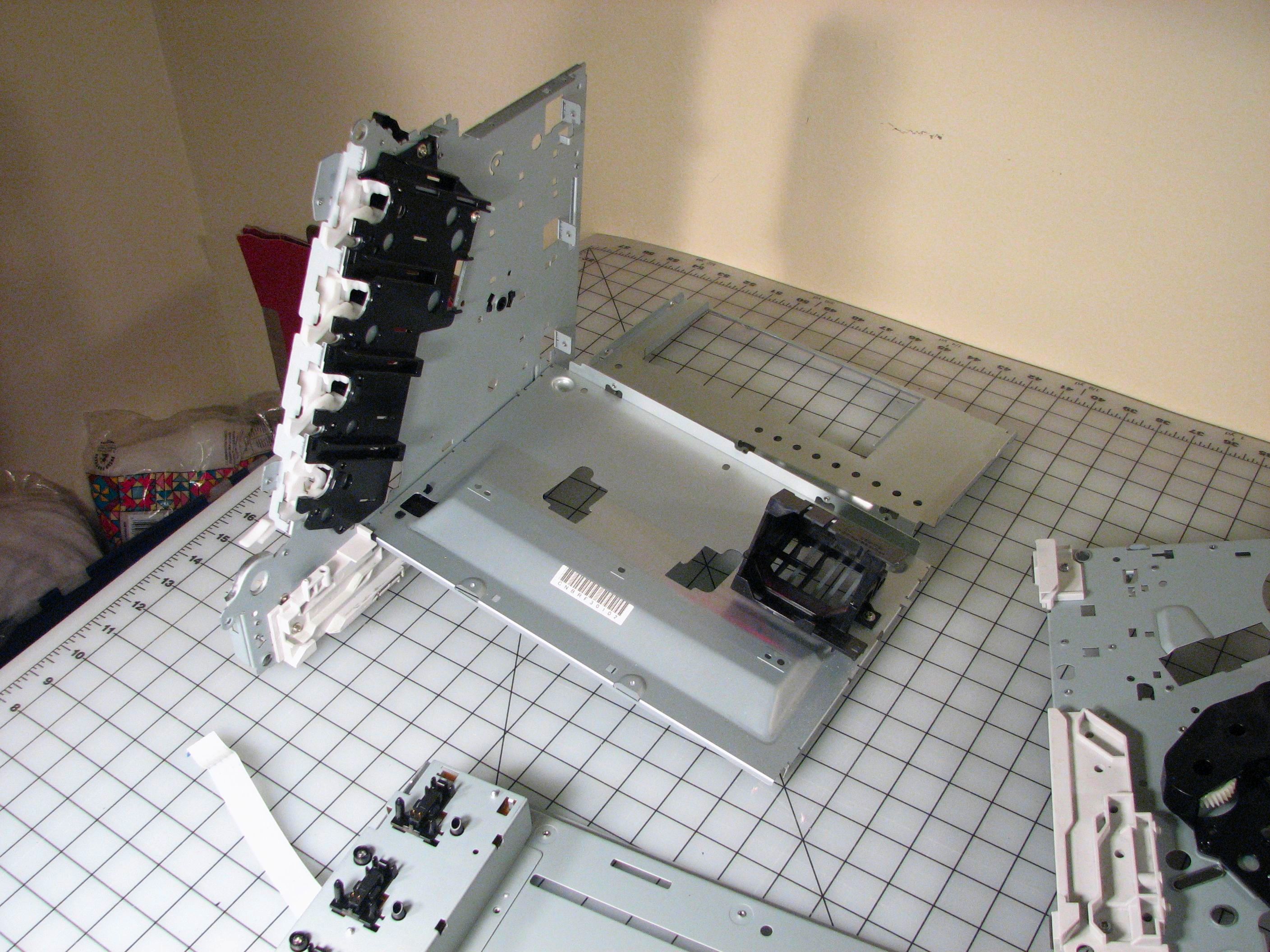
At this stage the printer is starting to look a little bit different. We can begin to see the underlying systems of levers and gears and things that perform the mechanical functions of the printer.
On the left side of the front door here is a vertical lever that controls little plastic tabs that sequentially open the covers for the photosensitive drums of the four toner cartridges. These are actuated as the user opens or closes the front door.
A similar set of levers on the right side of the front door is used to clamp the toner cartridges in place as the front door is closed.
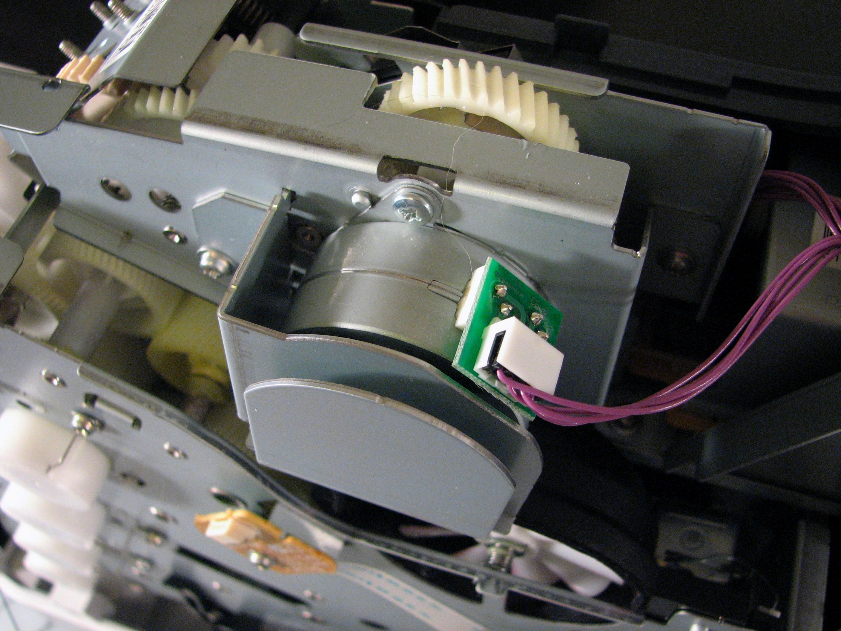
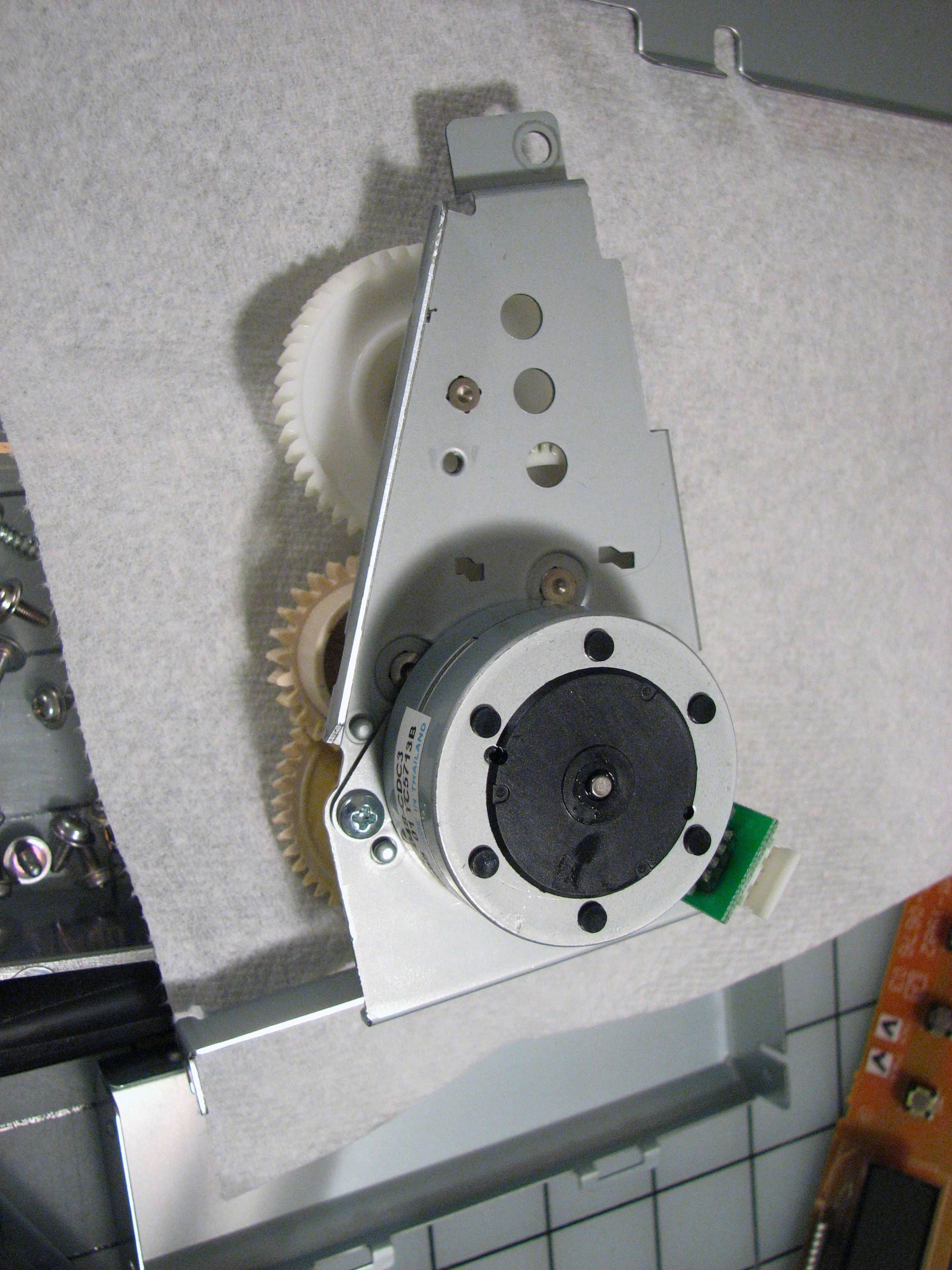
Speaking of gears and things, here’s one of the first motors. This one is up top, next to the fuser rollers. The motor is attached to a bracket with a few gears, and it leaves behind a few more gears when it’s taken out. It looks like these gears also drive the electrostatic belt, still attached to the front door of the printer.
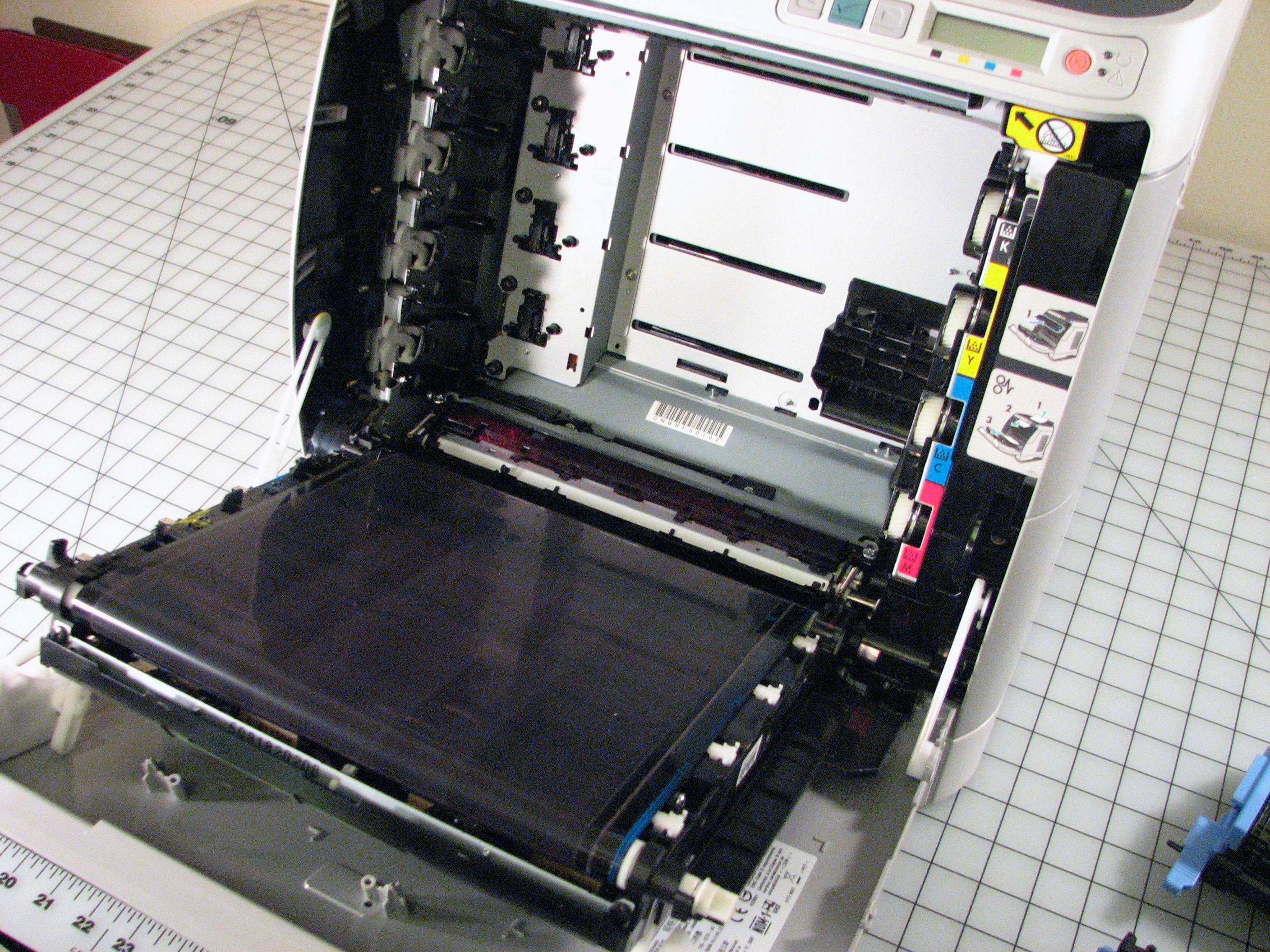
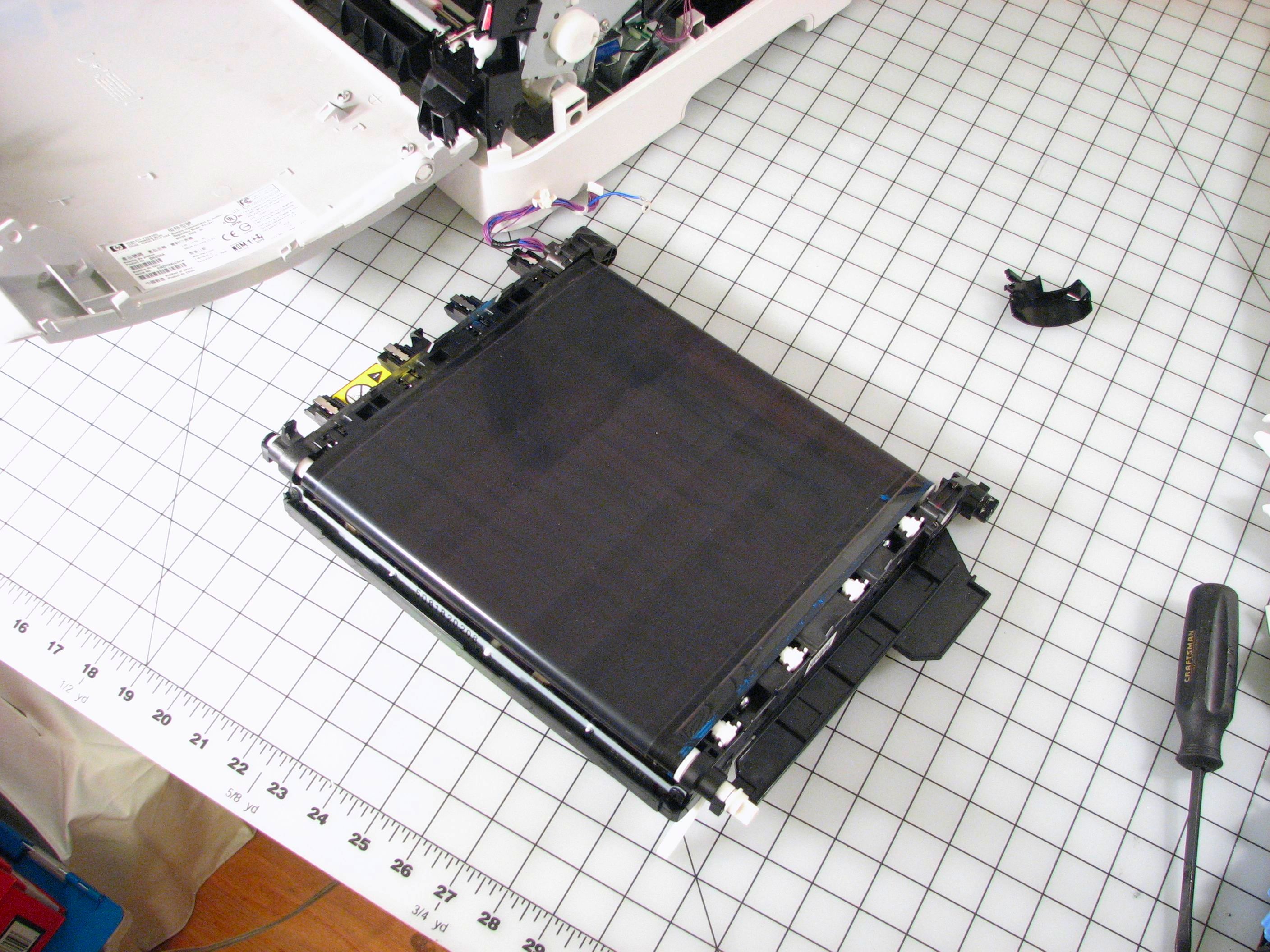
The Electrostatic Attraction Belt Unit uses static electricity generated by the high-voltage section to hold the paper in place and move it upwards across the four toner cartridges. It’s a bit like a Van de Graaf generator although maybe in reverse– high voltage sprays static charges onto the belt, which then hold the paper in place via “static cling.”
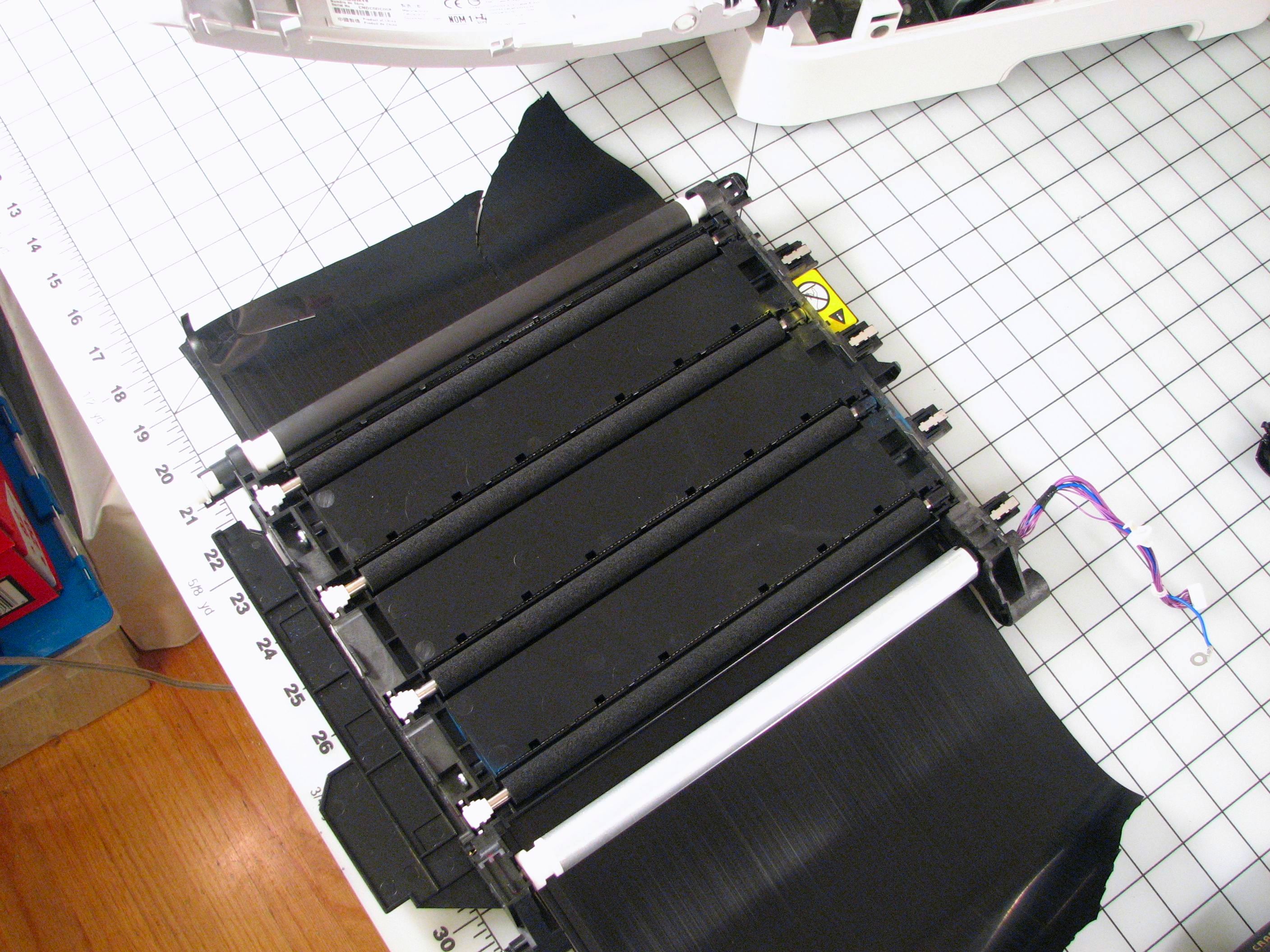
Above, the belt is cut open to reveal the four soft rollers inside that press the paper against the toner cartridges. There’s also a set of barbs by each roller that apply the static charges.
One might expect the rest of the belt assembly to be pretty obvious and skip taking it apart, but that turns out not to be the case. Besides the high voltage, there were a few wires running to it without any apparent purpose, so they must be followed!
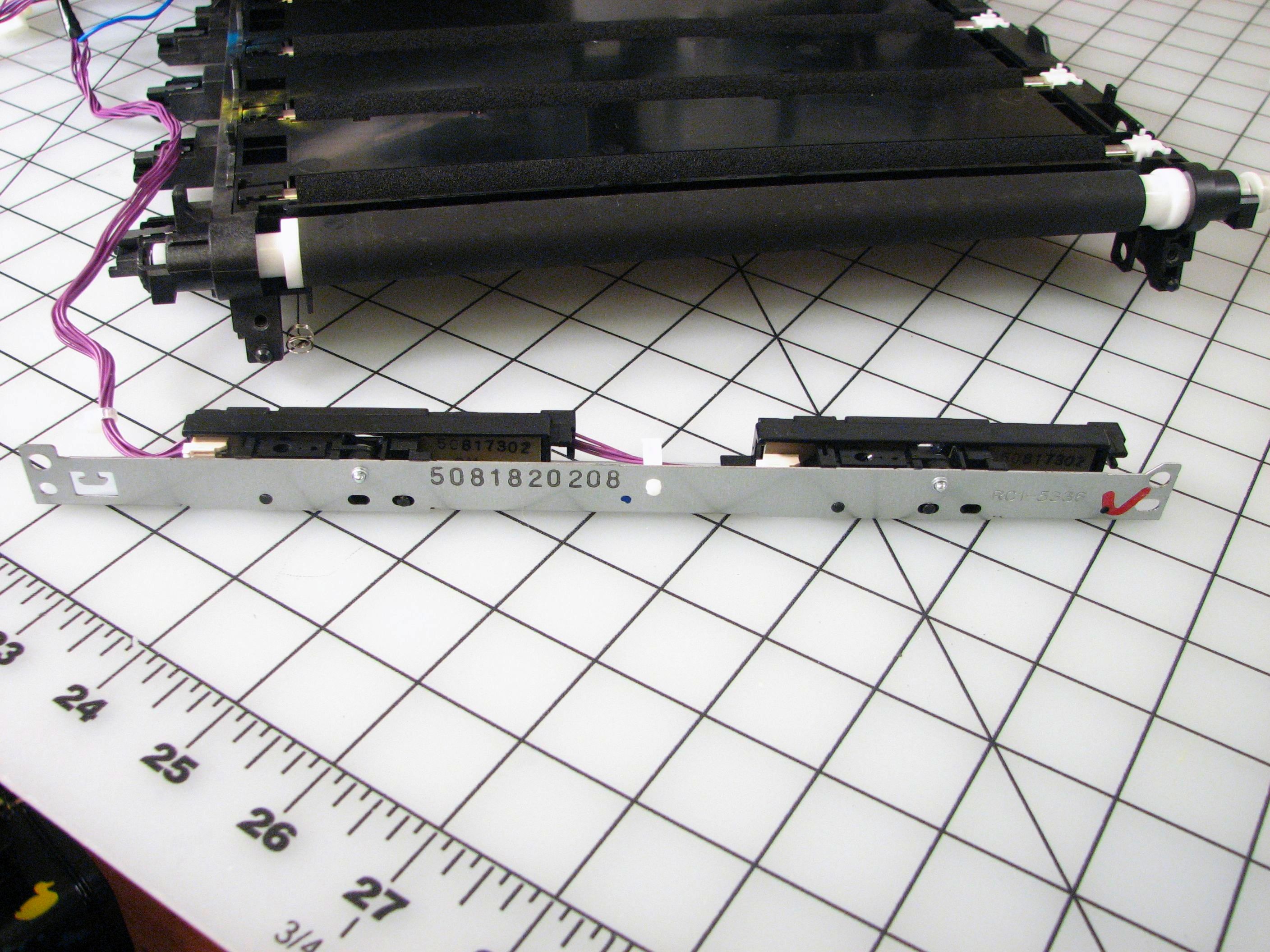
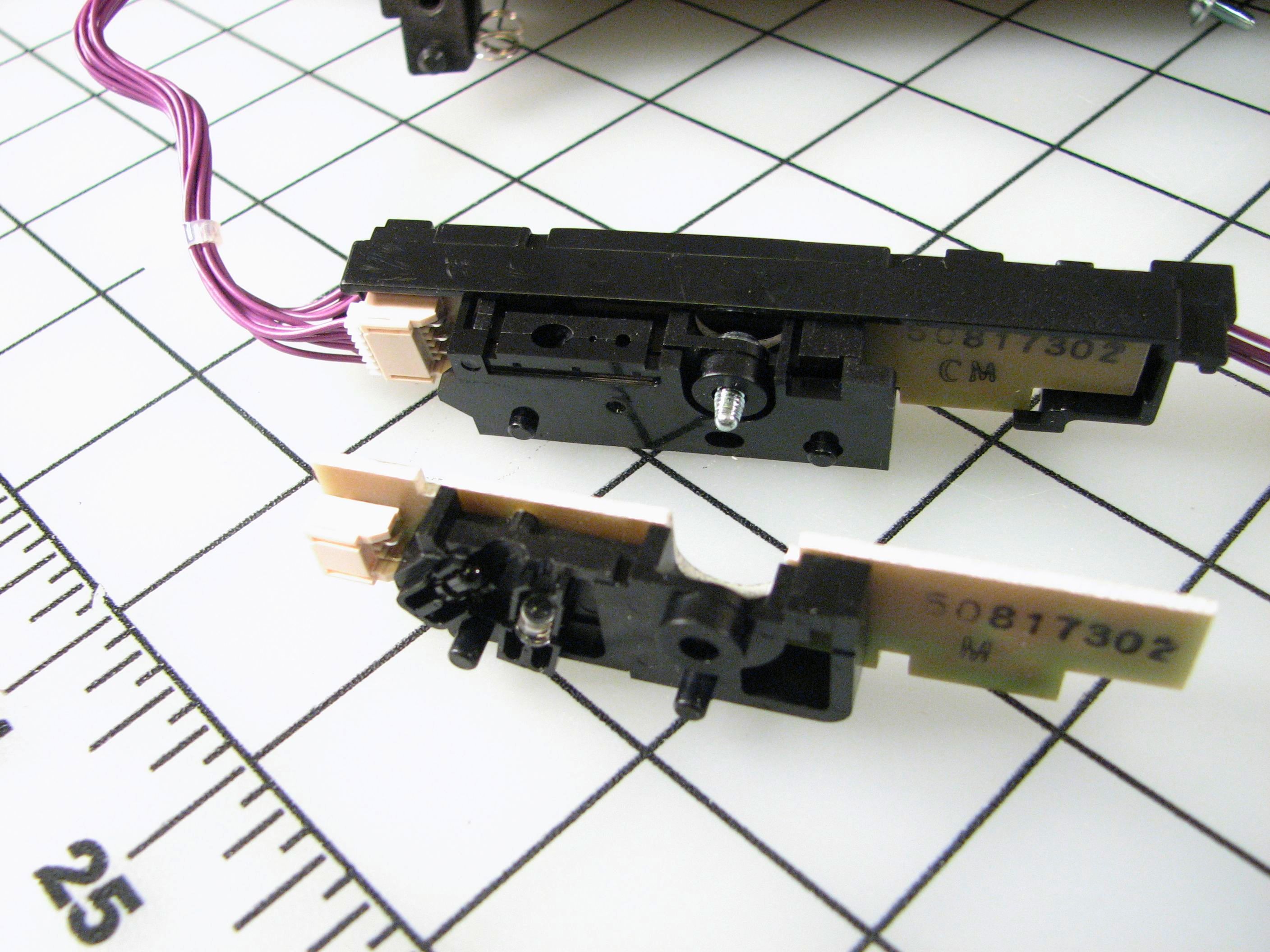
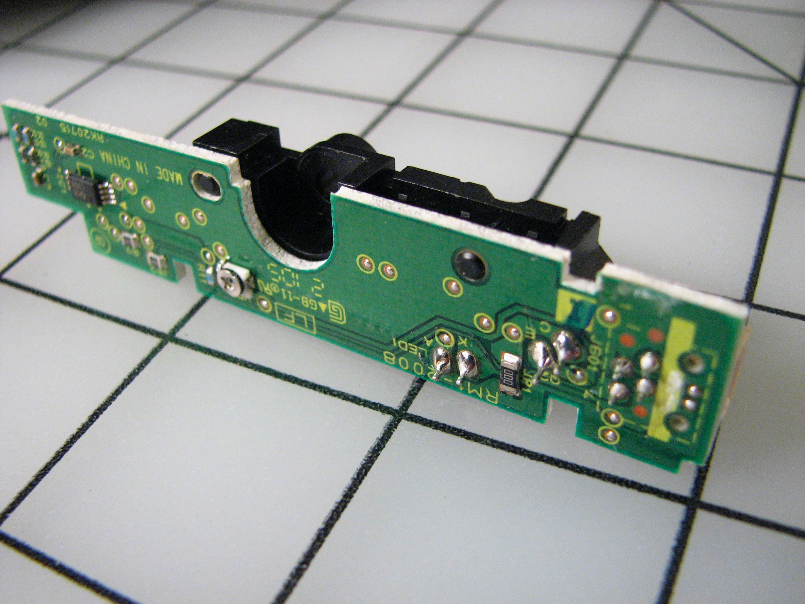
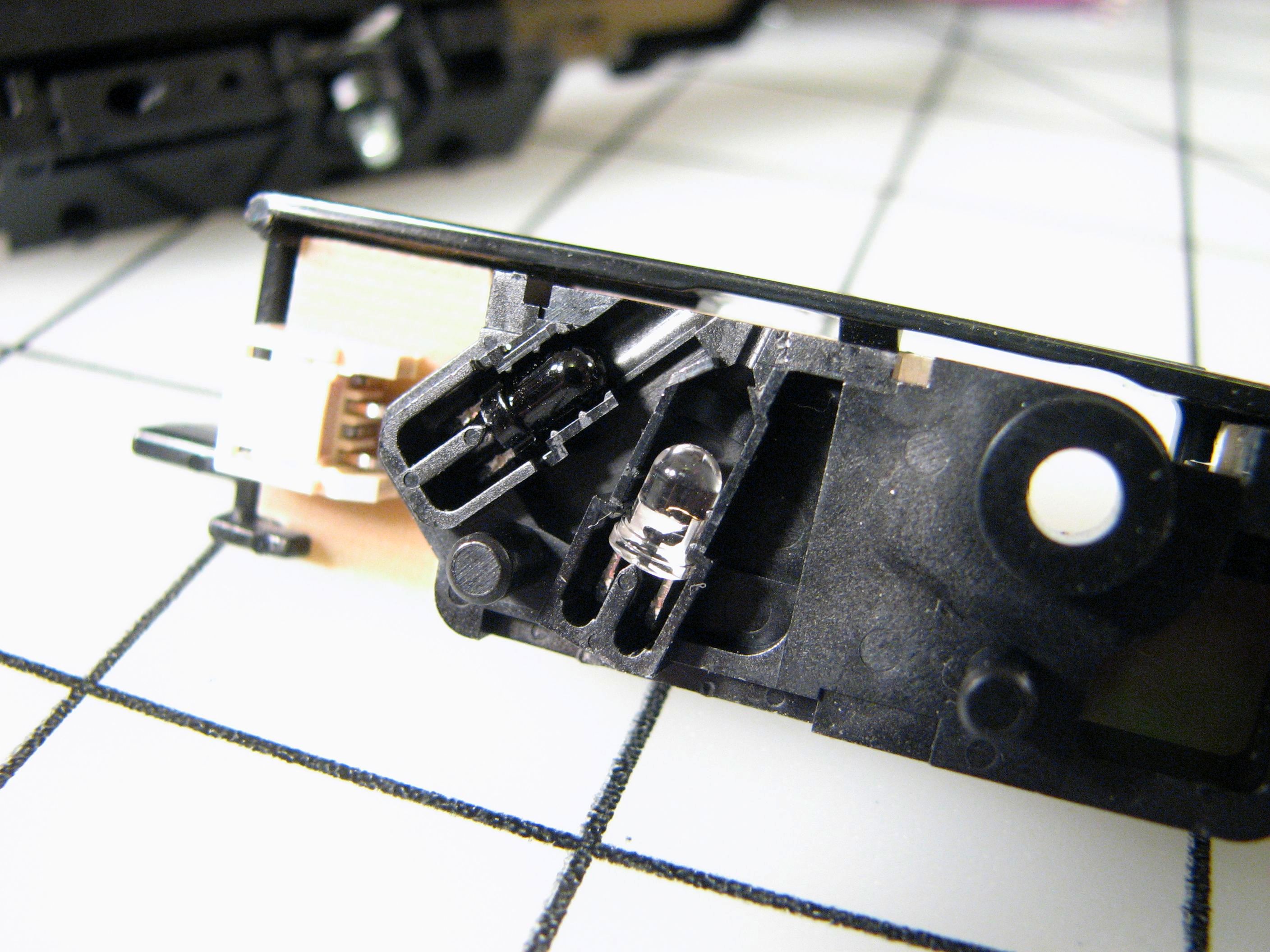
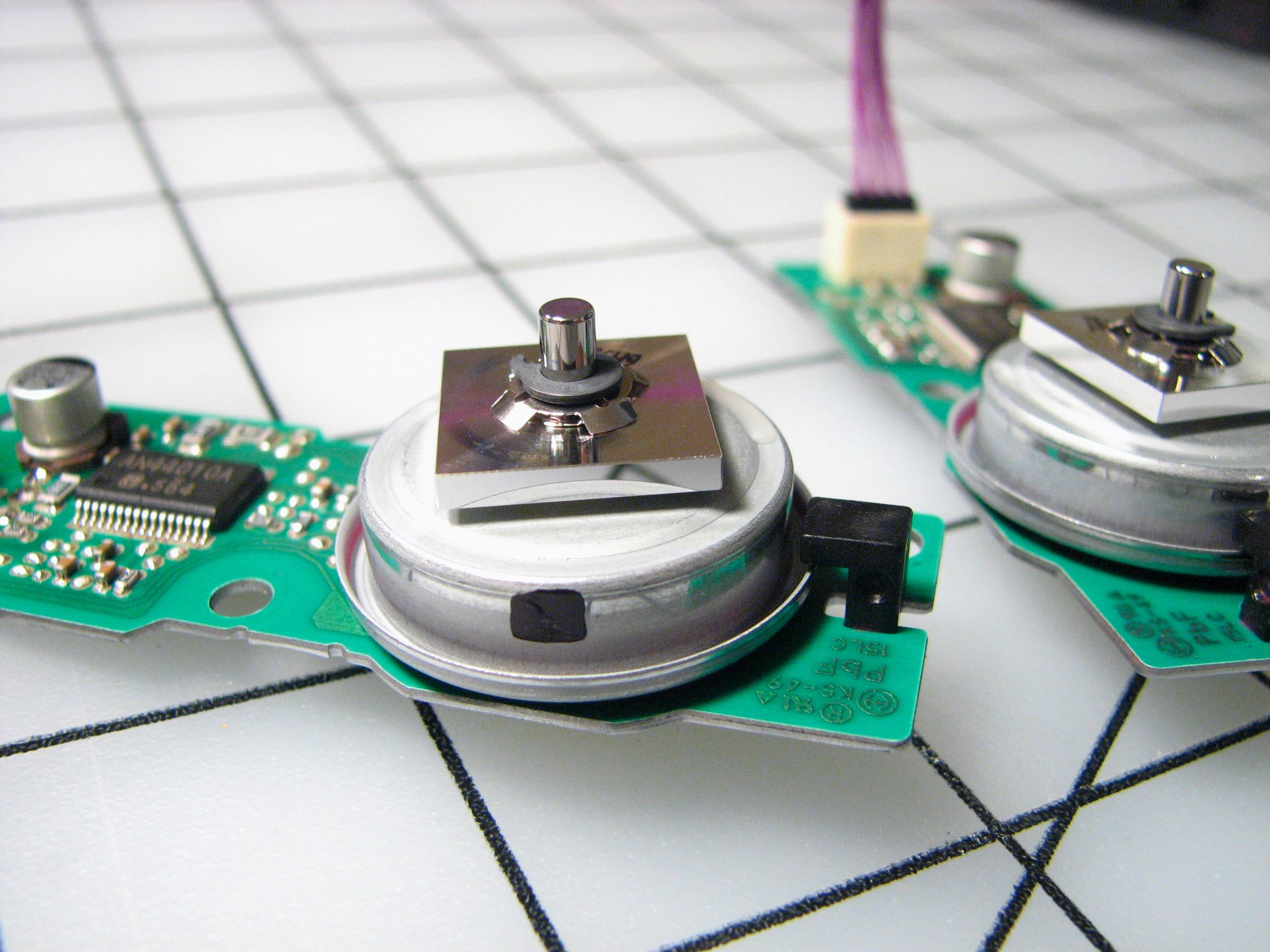
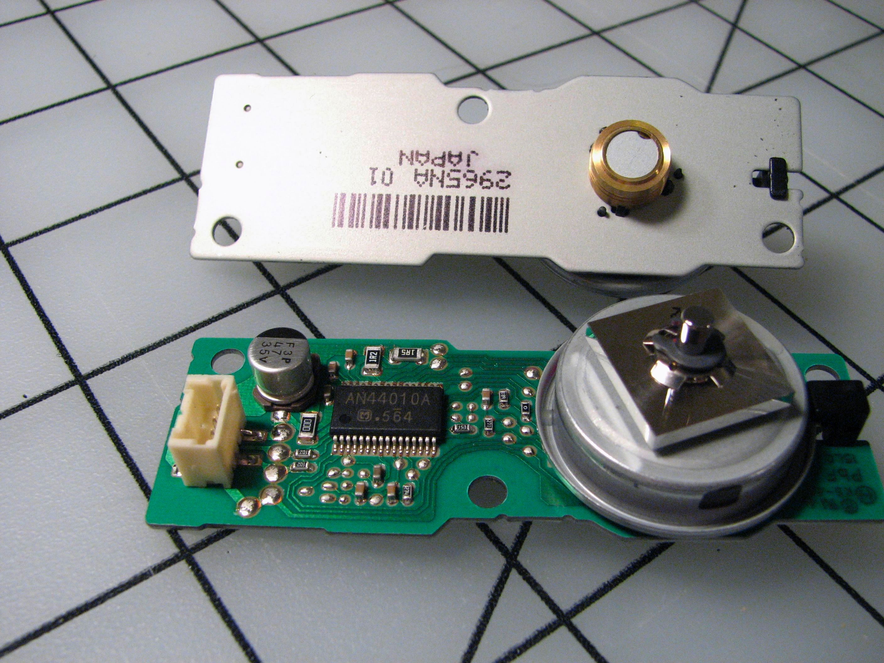
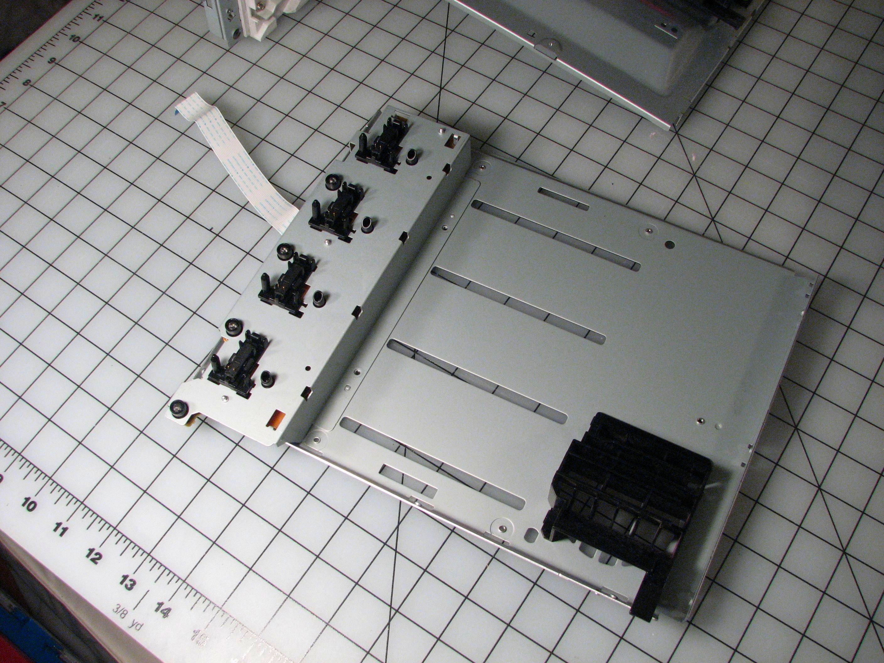
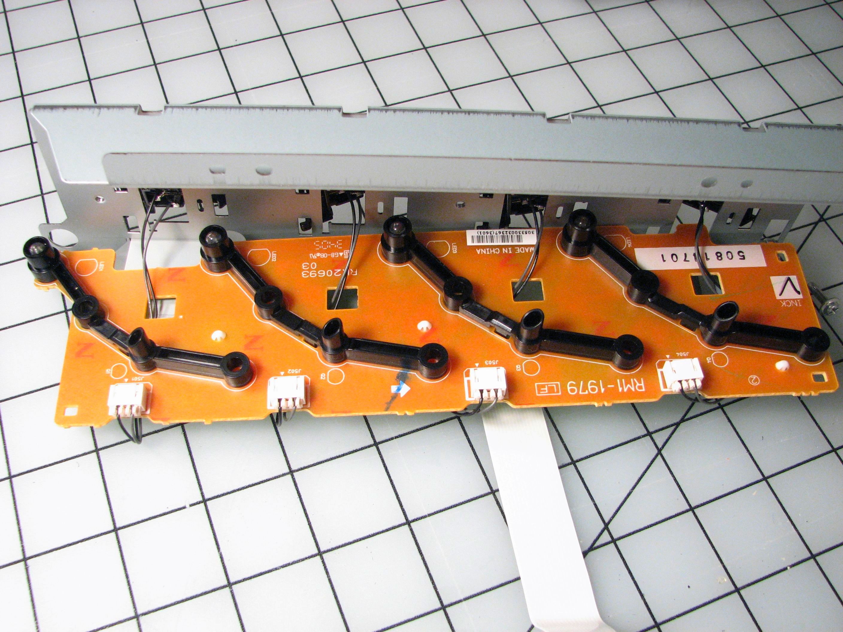
There were two little circuit boards hiding in there. Each one has an IR LED and phototransistor pair arranged as a surface reflectivity monitor. If you look closely at the picture of the circuit board you can see the anode and cathode of the LED labeled (A, K) and the collector and emitter of the phototransistor labeled as well (C,E). Nice of them to make it easy for us to figure out which way is which. So why monitor the belt? Officially, things like this are consumables, and the first priority of every part of this printer is to sell more printer parts. When the belt accumulates too much toner, it will no longer hold the paper effectively and needs to be replaced. And, you can judge the amount of toner build-up by looking at the surface reflectivity of the belt. (*Two* sensors. They really want to sell you that new belt.)
A good sign.
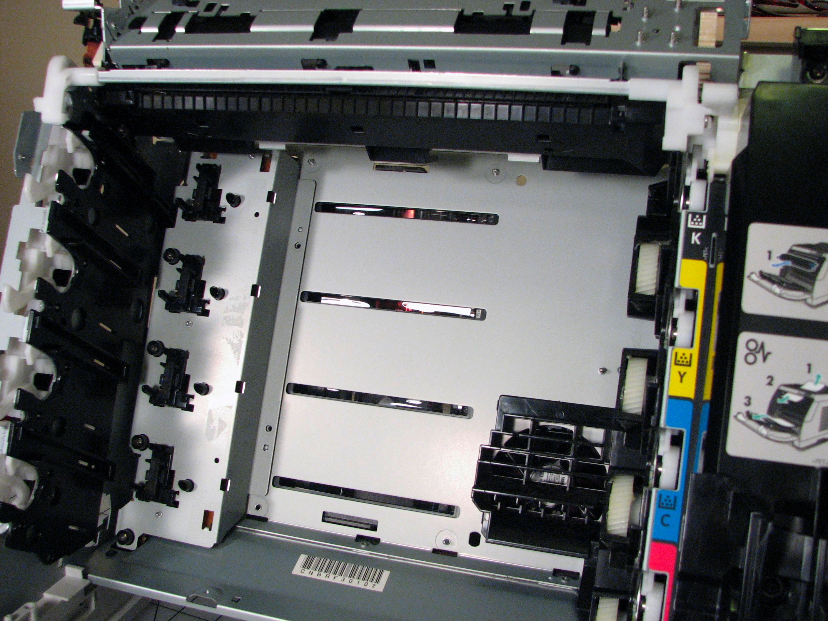
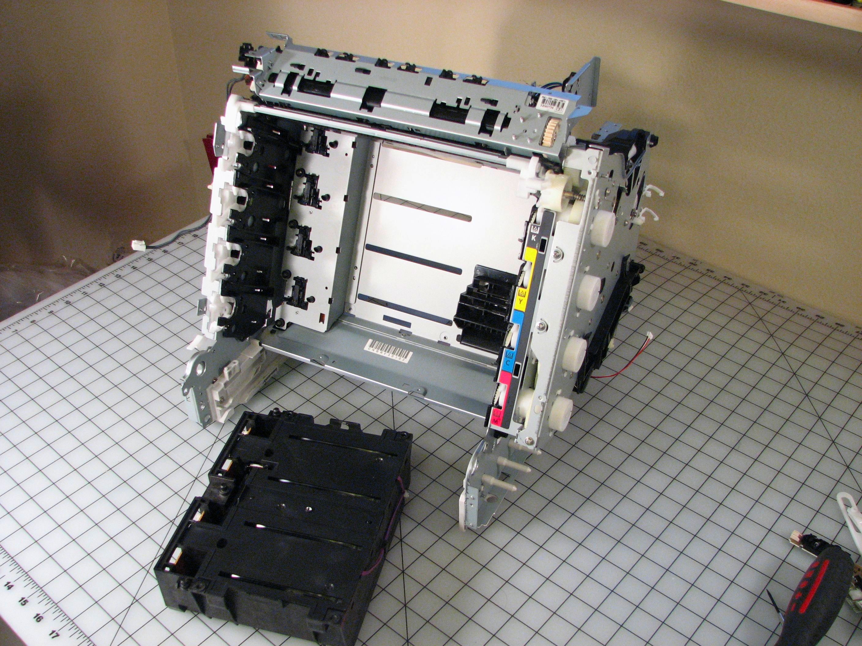
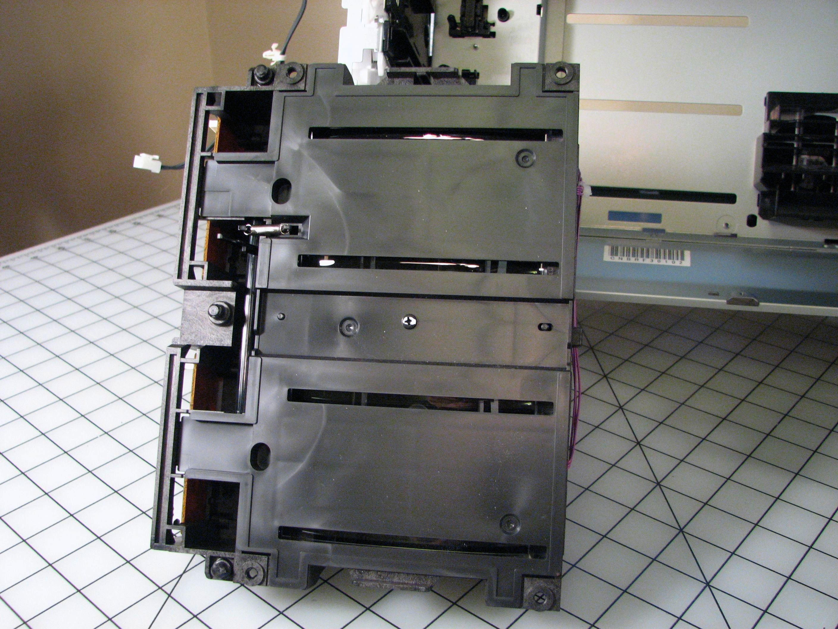
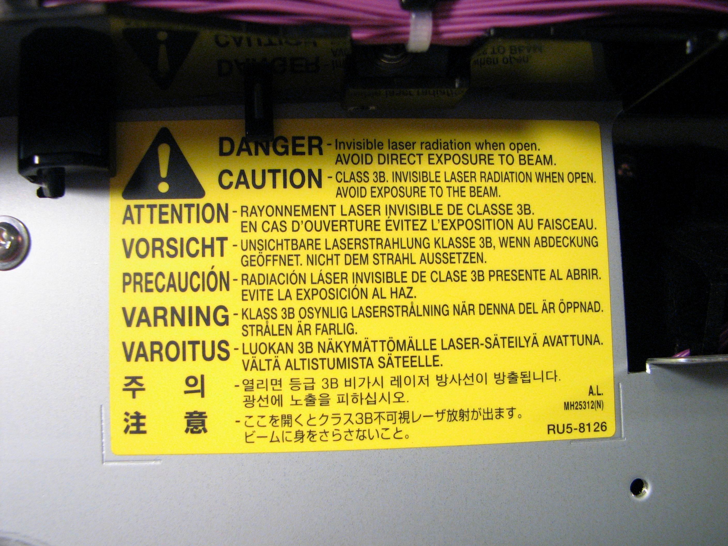
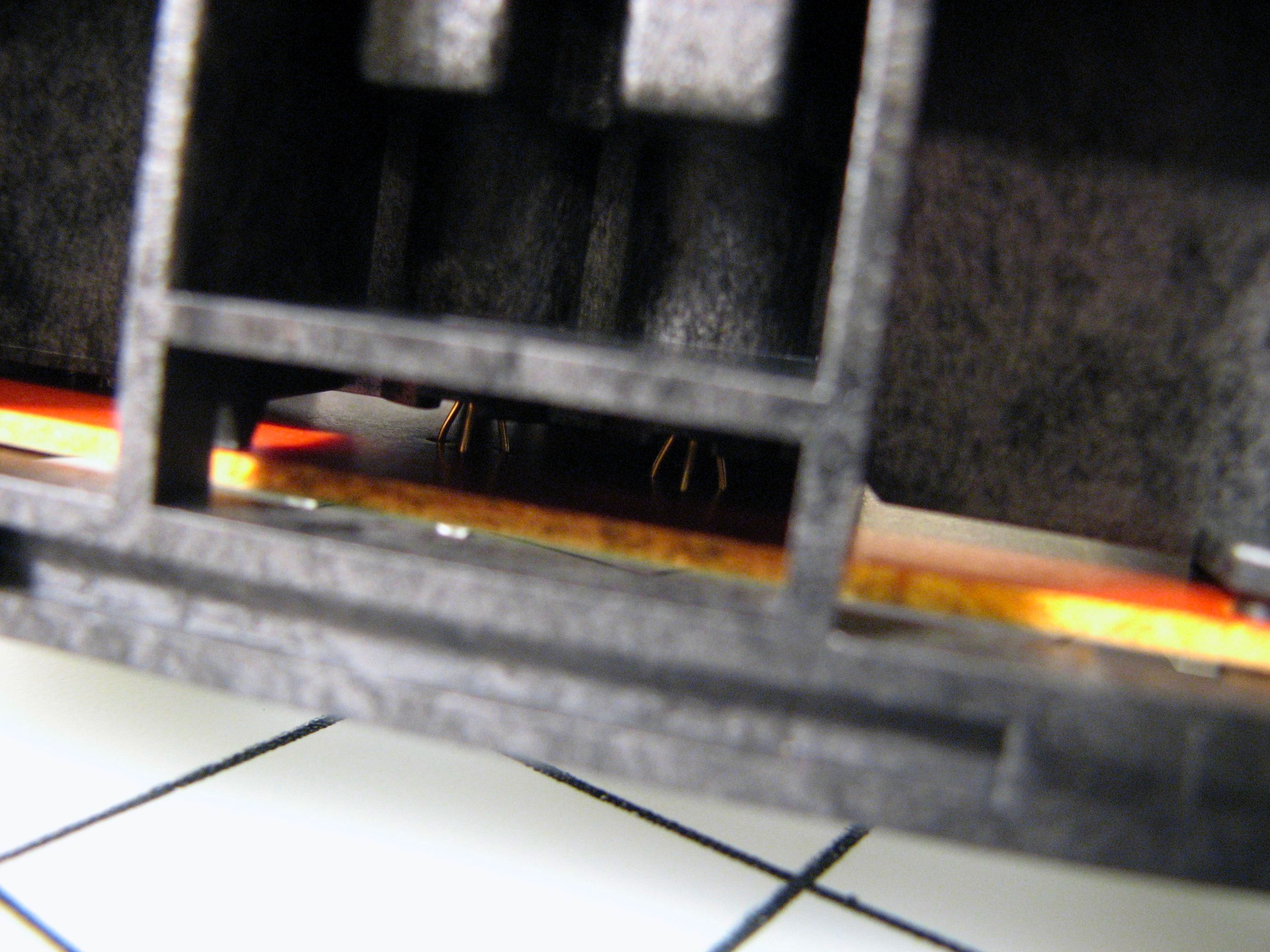
Deep in the inner sanctum of the printer hides the optics package. If you open the front drawer of the printer and pull out all the cartridges, you can see some thin black horizontal stripes. Upon closer inspection you can see that each of those stripes contains a long skinny lens with a reddish glare. After taking off the back panels of the printer, we can see that these lenses belong to a big black plastic box. This is the optics package, where all of the lasers, lenses, mirrors, and sensors are hidden away. Yup: it’s not a laser printer without a laser. The big technological change that has made color laser printers relatively inexpensive over the last decade is that lasers became inexpensive. That allows a printer like this to use four independent lasers rather than some of the older single-laser methods, e.g., toner cartridge turret.
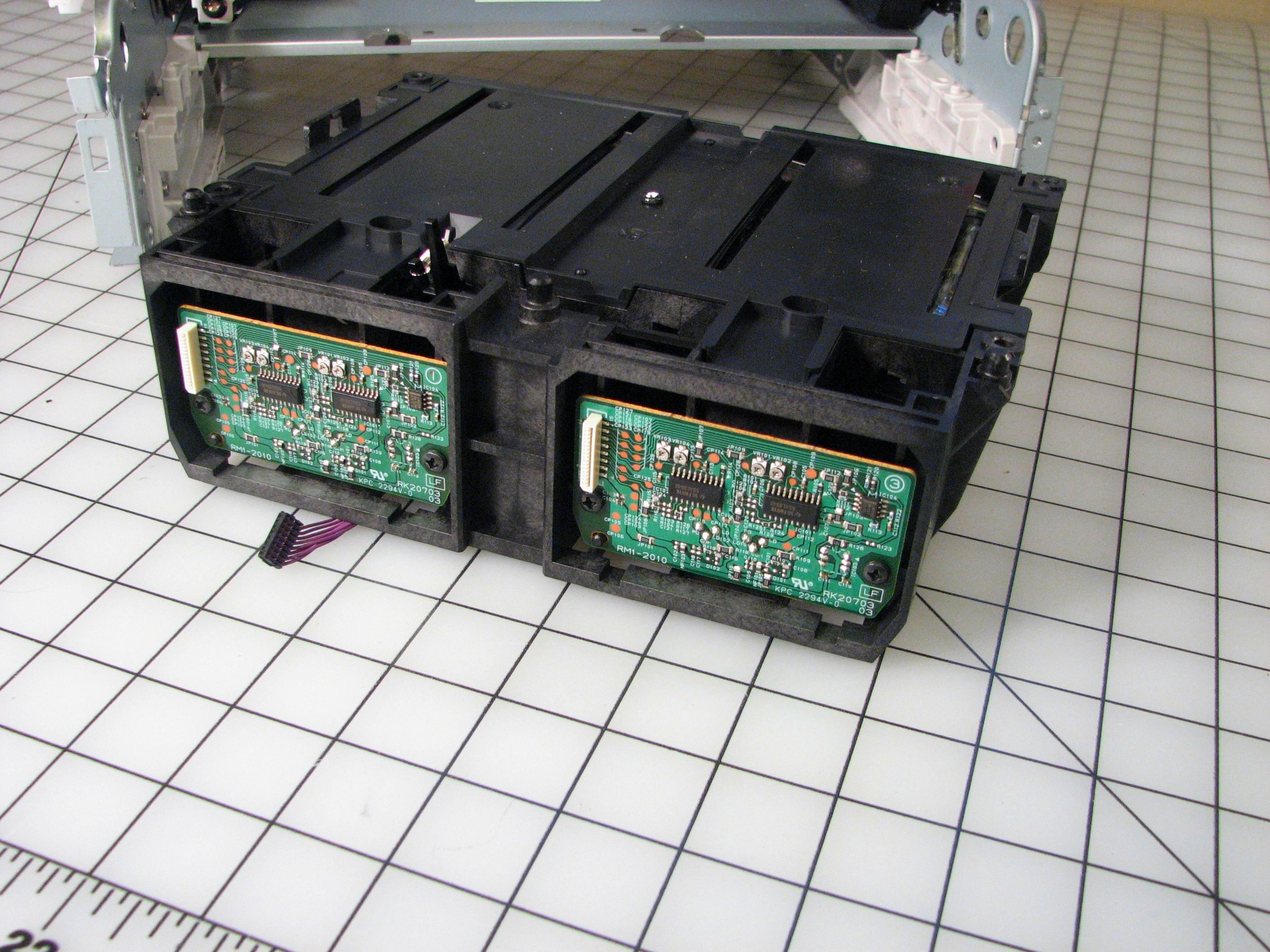
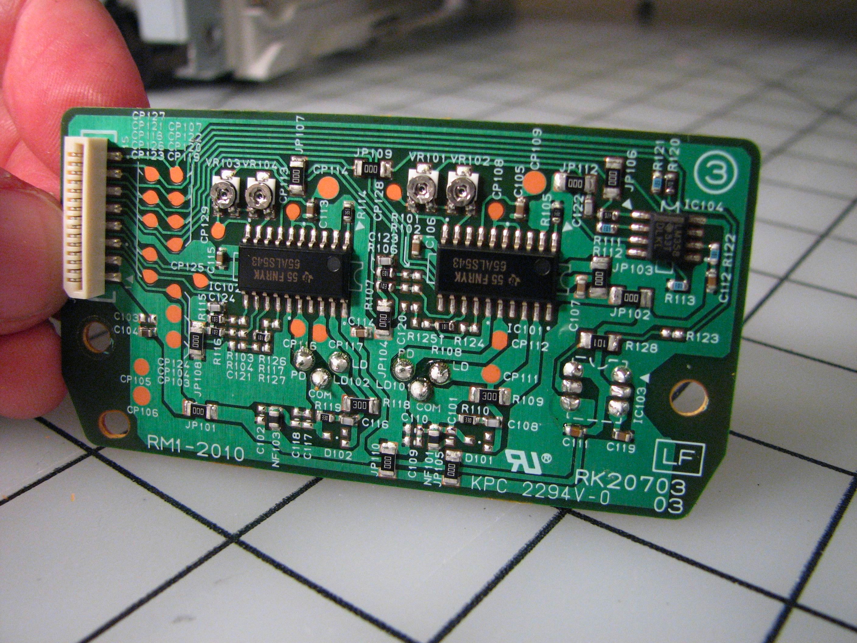
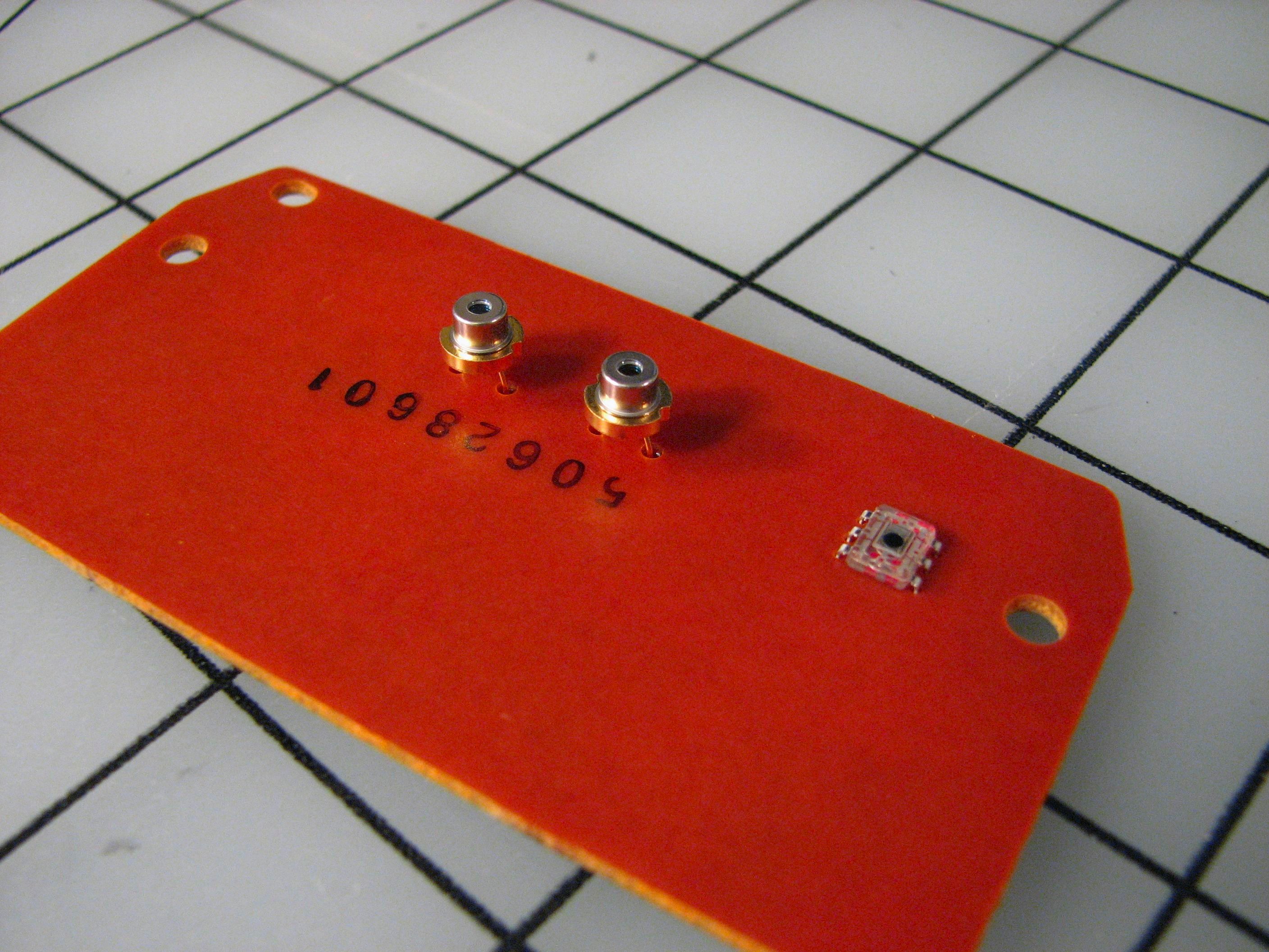
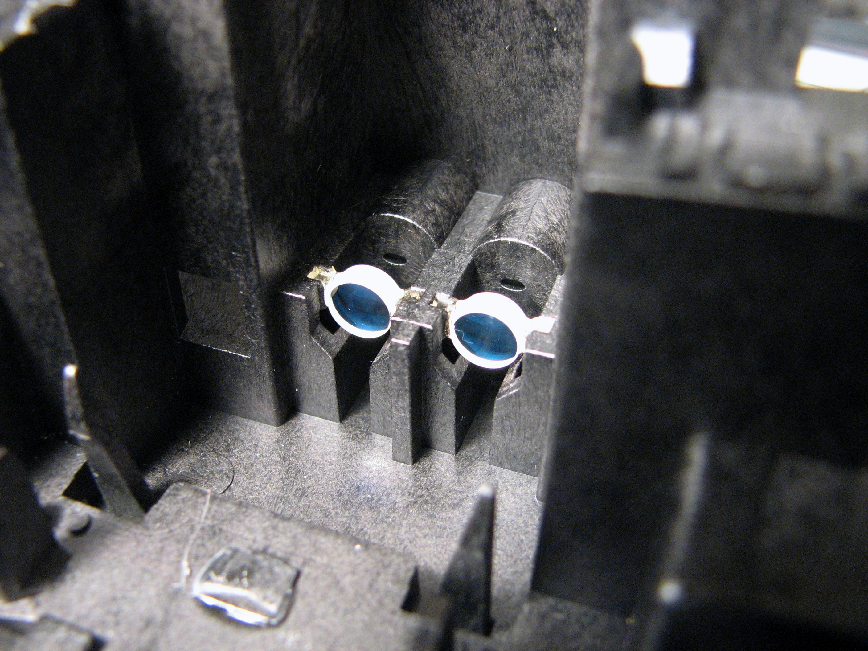
On the outside of the optics box are two little circuit boards with two laser diodes each. You can look through the edge where the circuit boards are installed to see the two little laser cans. If you look closely at the laser diode circuit boards, you can see where the laser diodes are attached– their pinouts are even labeled as to which of the three pins is the PD and LD! Bad news: the LEDs aren’t marked so you don’t know what maximum current they are rated for. Good news: even if you kill one playing with it, there are still three others. :)
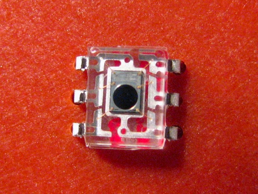
Besides the two laser diodes on those circuit boards, there is one other optical component, shown here close up. It is a small photodiode in a clear SOIC-6 package with what appears to be several independent pins– this may be a position sensitive detector. As we’ll see in a minute, the optics package contains rotating mirrors. As a rotating mirror sweeps the laser beam across the photosensitive drum it also sends the laser onto this detector, which allows the printer to synchronize the data stream with the laser’s position as it scans out a page.
Next: Inside the optics package:
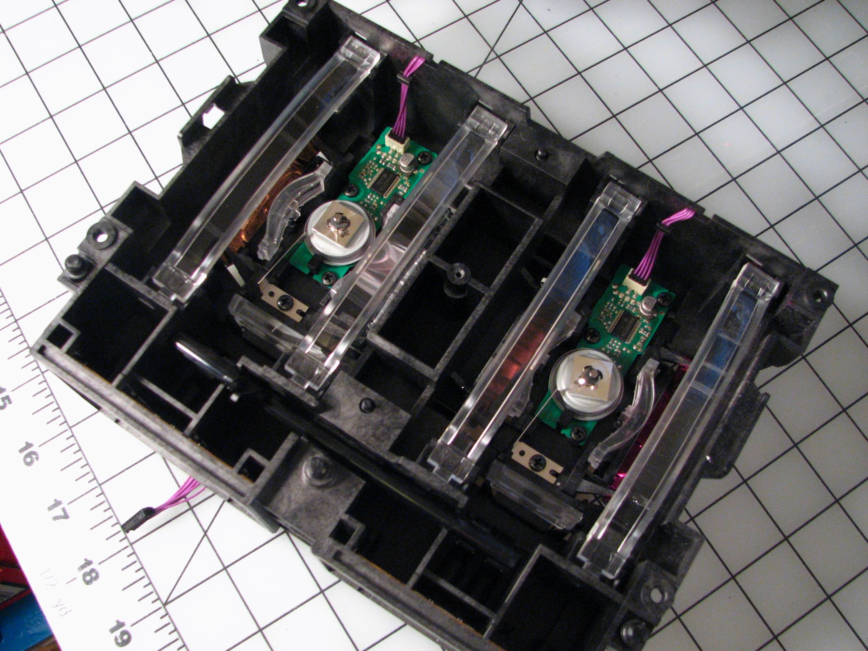
The optics package has two neat halves. Each half has its own laser diode board (as we have seen) with two laser diodes. The lasers each point through a collimating lens, through a second line-generating lens, and then onto a fast rotating square mirror that moves the narrow edge of the line across the photosensitive drum in a toner cartridge. After the rotating mirror, there is a second pair of aspheric lenses that form a compensated telescope to keep the laser beam focused as it scans across the page. The telescope is folded in the middle by a moderately sized first-surface mirror (2.5″ x 3/8″).
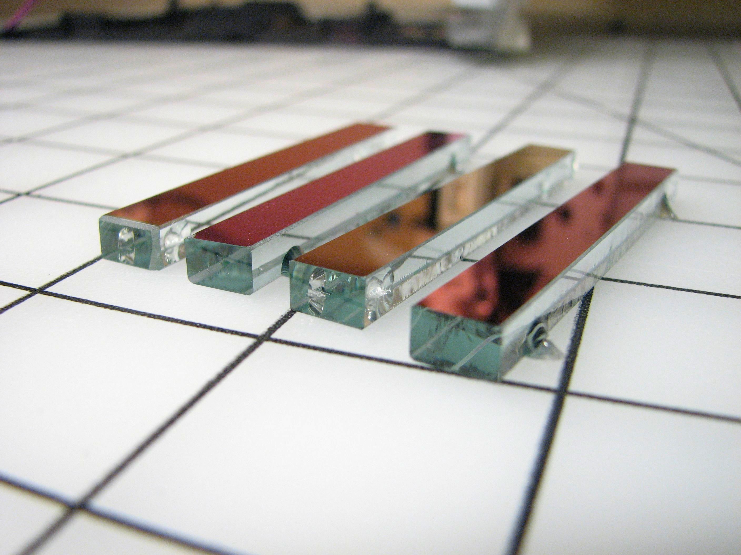
Two of the glass collimating lenses (left) and the large mirrors (right). The lenses are optical glass and have an anti-reflection coating. All of the lenses are glued into place with clear epoxy. For the plastic lenses, this isn’t a problem– they can easily be pried loose. The four glass lenses are a different story– I managed to crack two of them when trying to pry them loose. These are the only parts of the machine that I was not able to remove in a reversible process. My advice if you want to recover these glass lenses: cut the glue around the instead of trying to pry them off.
The glass mirrors are also glued in place, but actually slip out of place easily by bending the tabs that they are glued to. While these appear to be moderately high quality mirrors, note that they are on a cheap greenish soda-lime (“window glass”) substrate.
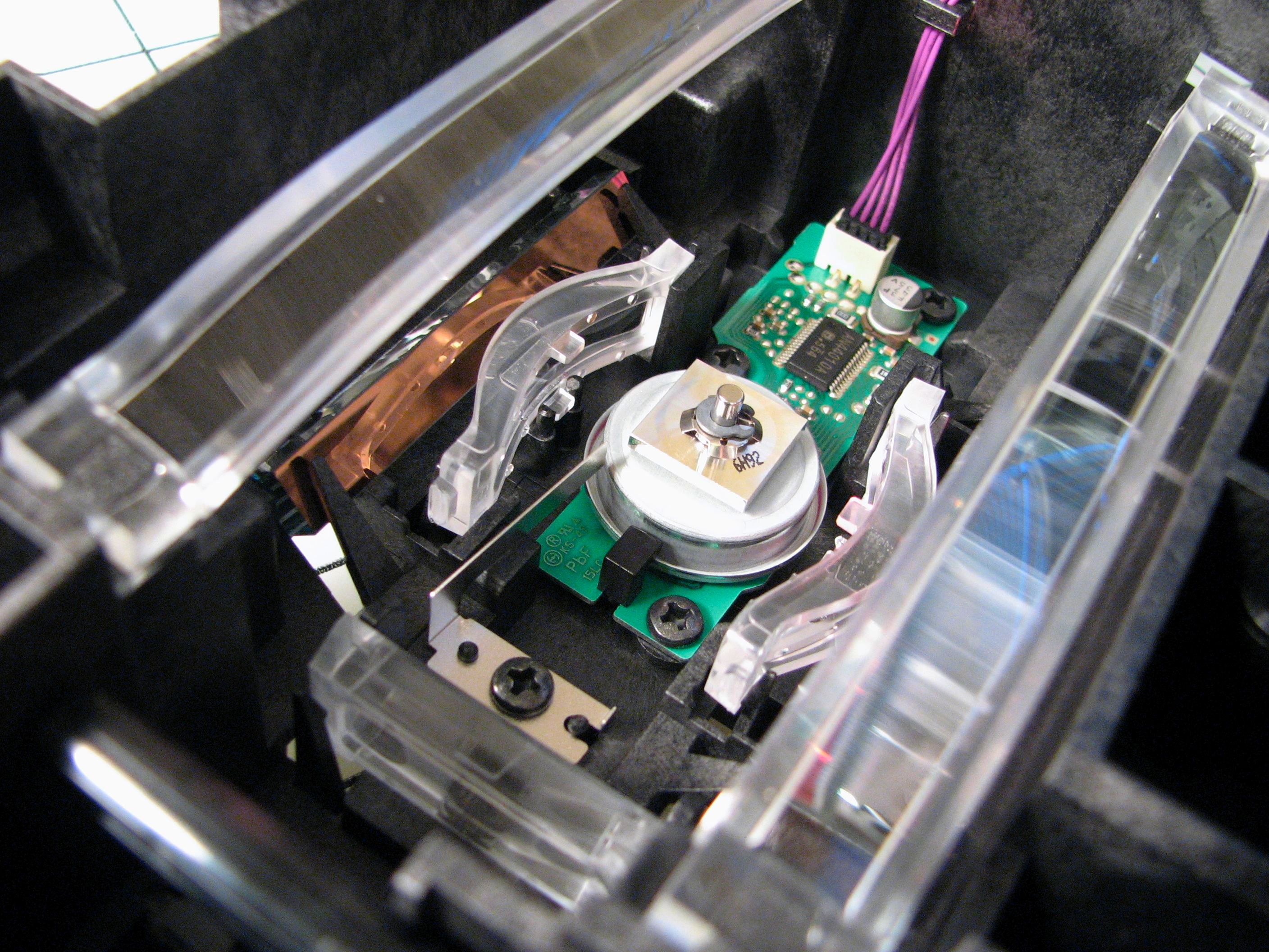
The rotating mirror is a square of polished metal, presumably aluminum. It sits on a dc brushless motor on a little circuit board. For thermal reasons, the circuit board is actually one with an aluminum substrate.
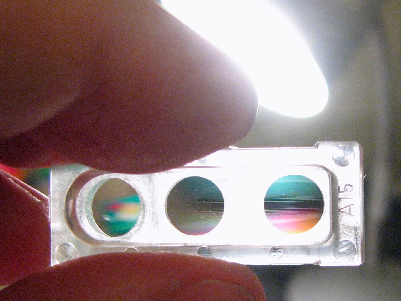
Here is one surprising element from the optics package. This is a precision molded plastic lens assembly with three lenses. The lens on the left is a plain (near cylindrical) convex lens that focuses light onto the photodiode that we saw earlier. The other two lenses are for the beams coming from the laser diodes towards the rotating mirror. As you can see in the lens on the right, it’s not an ordinary lens, but a cylindrical lens that has rulings on it– probably a cylindrical fresnel lens. The rulings diffract light, however, so it’s really something to look at.
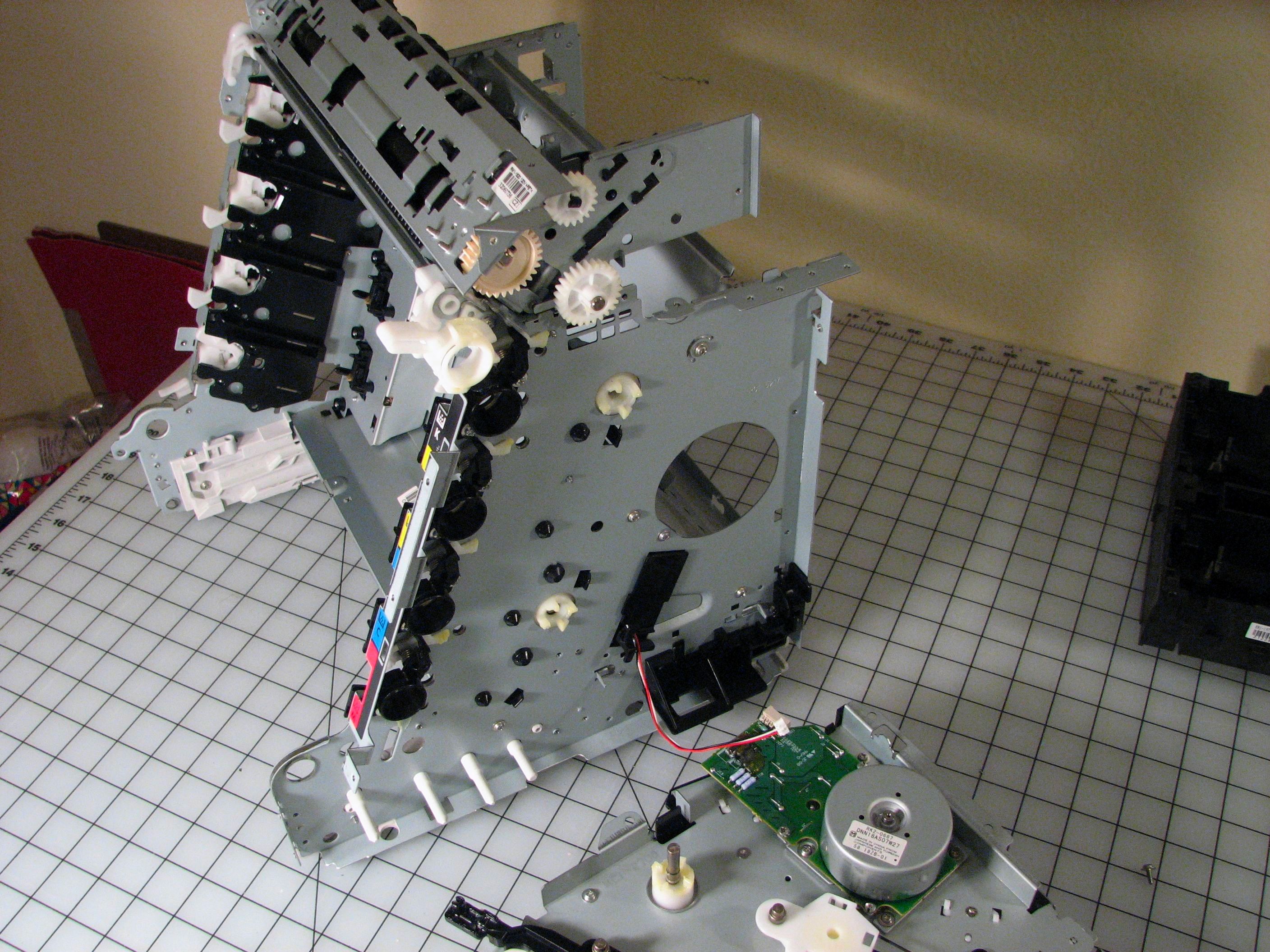
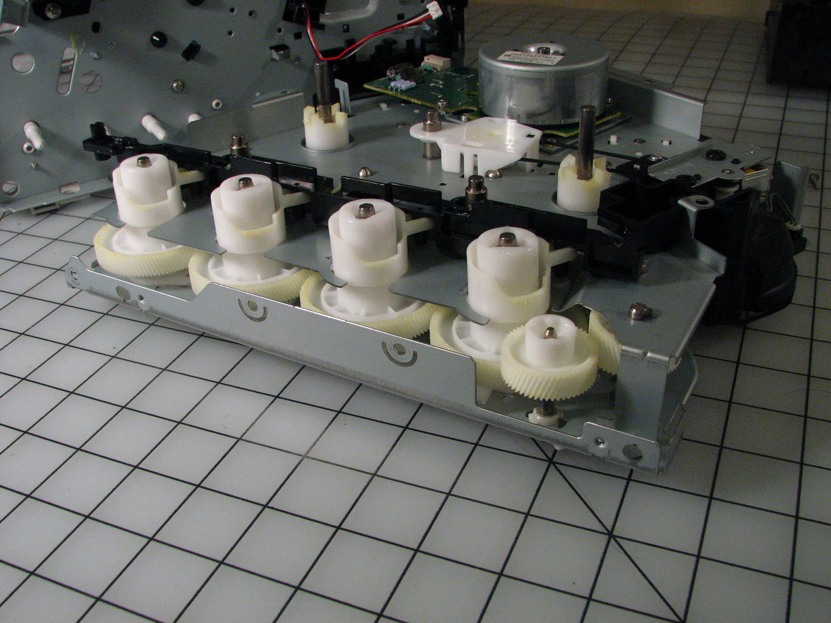
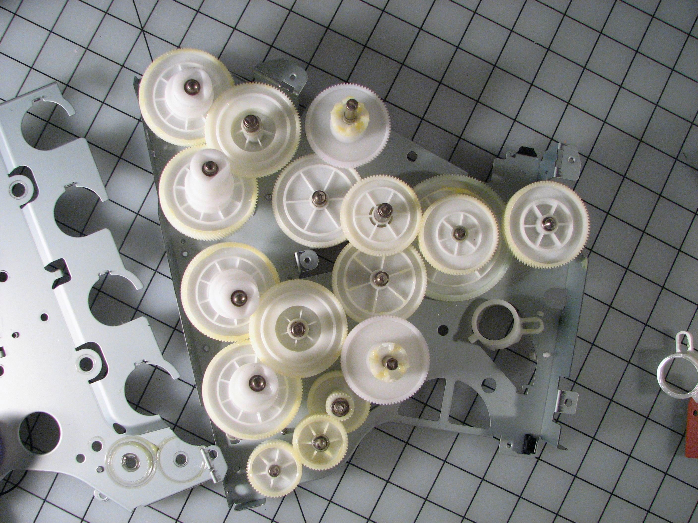
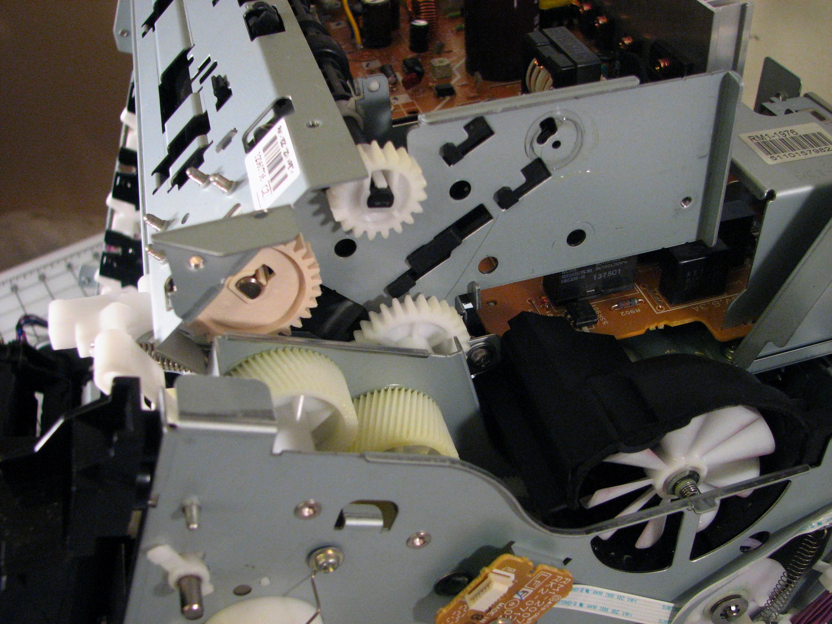
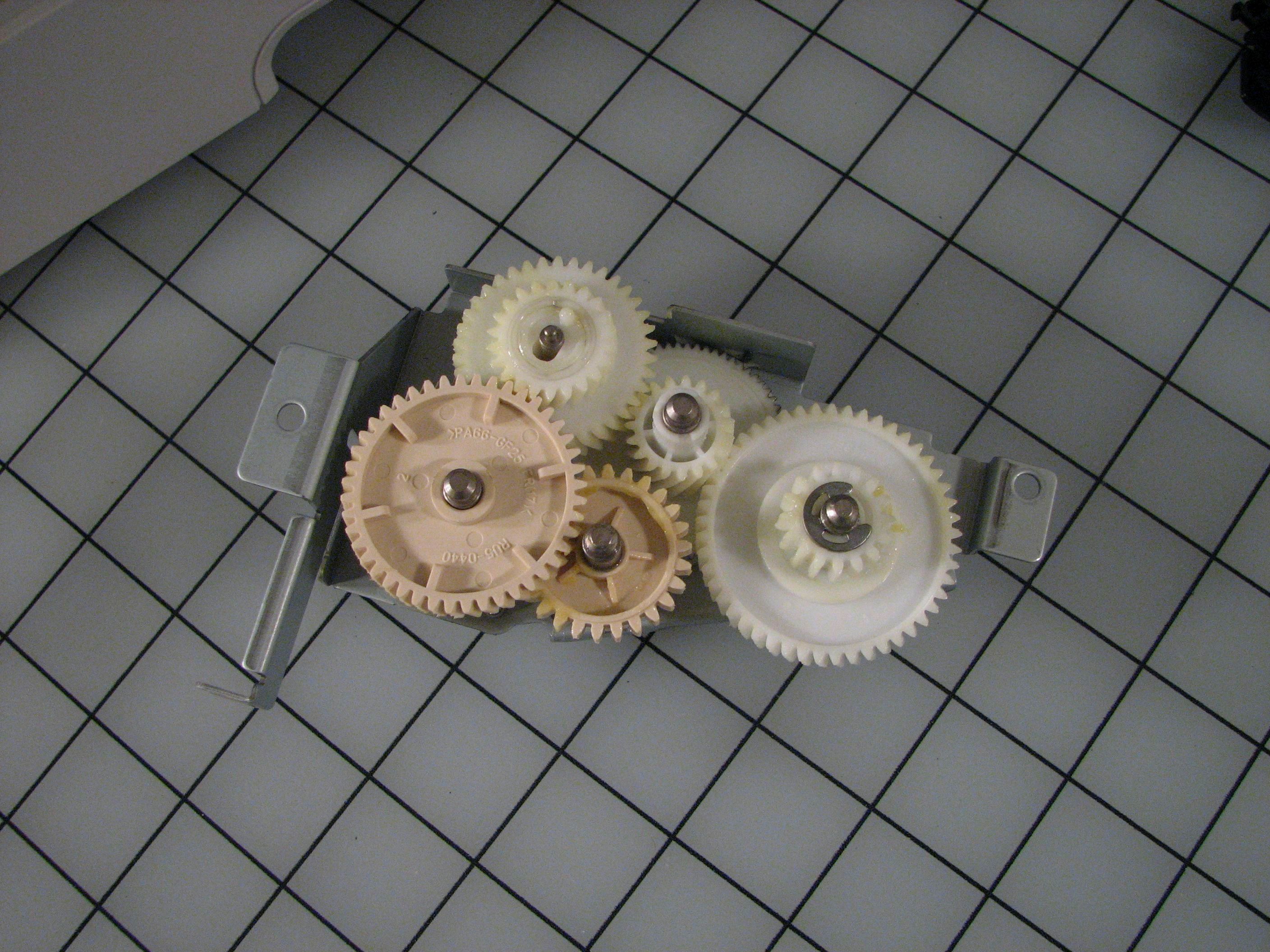
One thing that we have alluded to thus far is the mechanical complexity of the machine. It really isn’t to be taken for granted. The gear train shown above lives in the right side of the machine and drives the rollers of the toner cartridges. If you want plastic gears, this printer offers a good value for your money. No, this isn’t all of them.
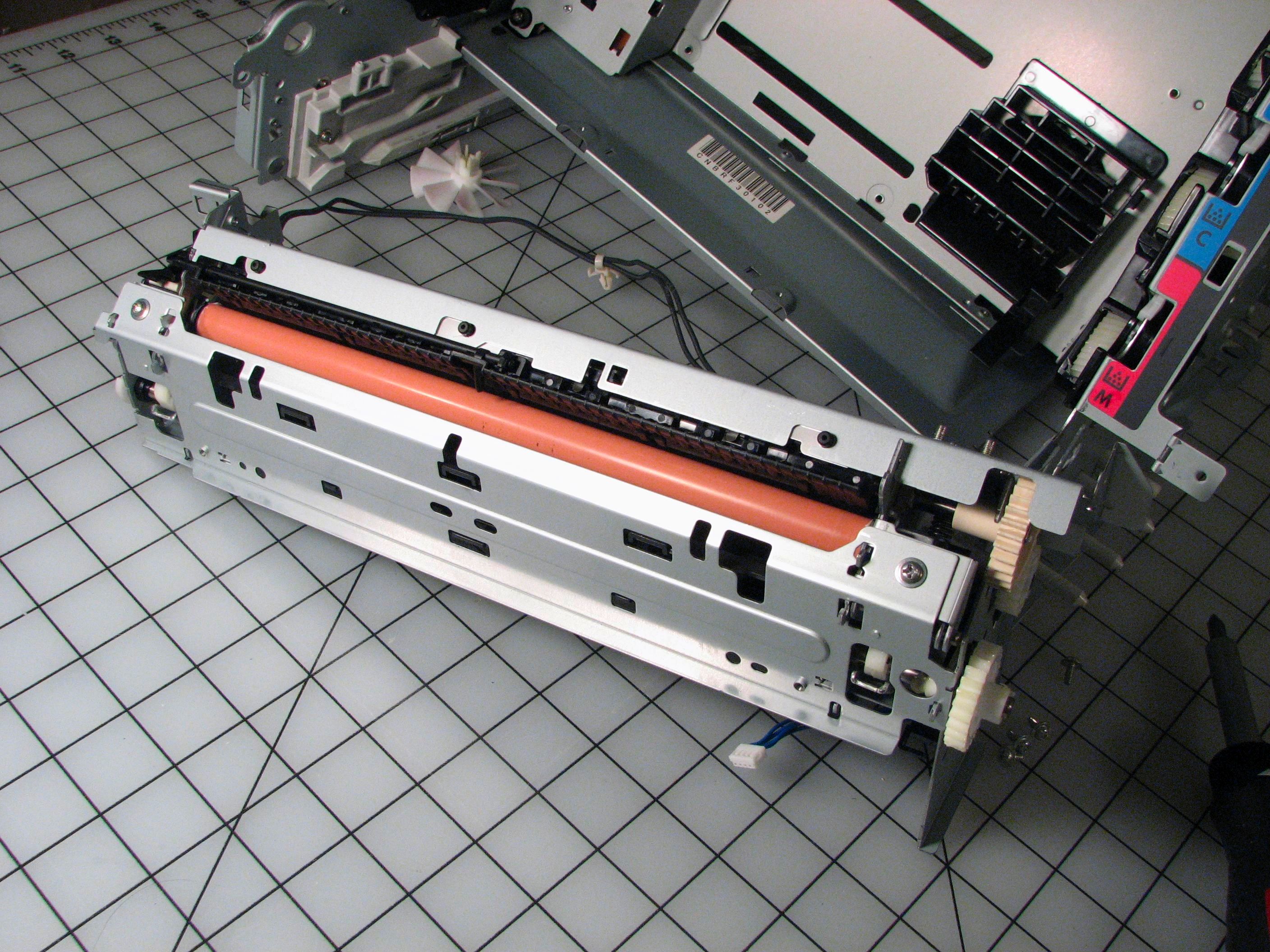
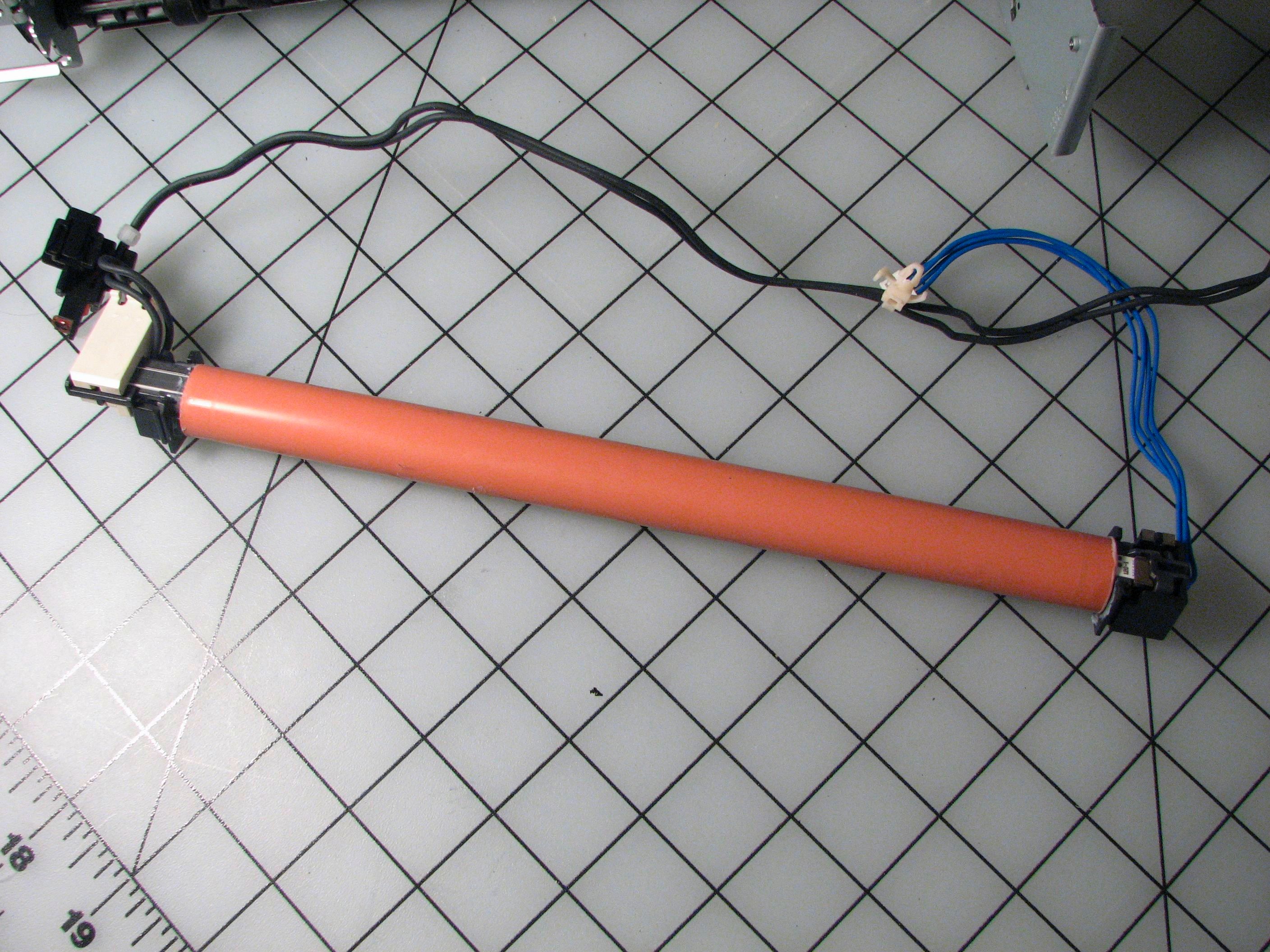
After the optics, we come to the fuser assembly that sits atop the printer and melts the toner onto the paper. The assembly consists of a pair of rollers, where the orange one contains a heater. The “standard” technology for a fuser roller is a quartz lamp– not exactly exciting. But, we took it apart anyway and were rewarded with a pleasant surprise: there was no quartz lamp.
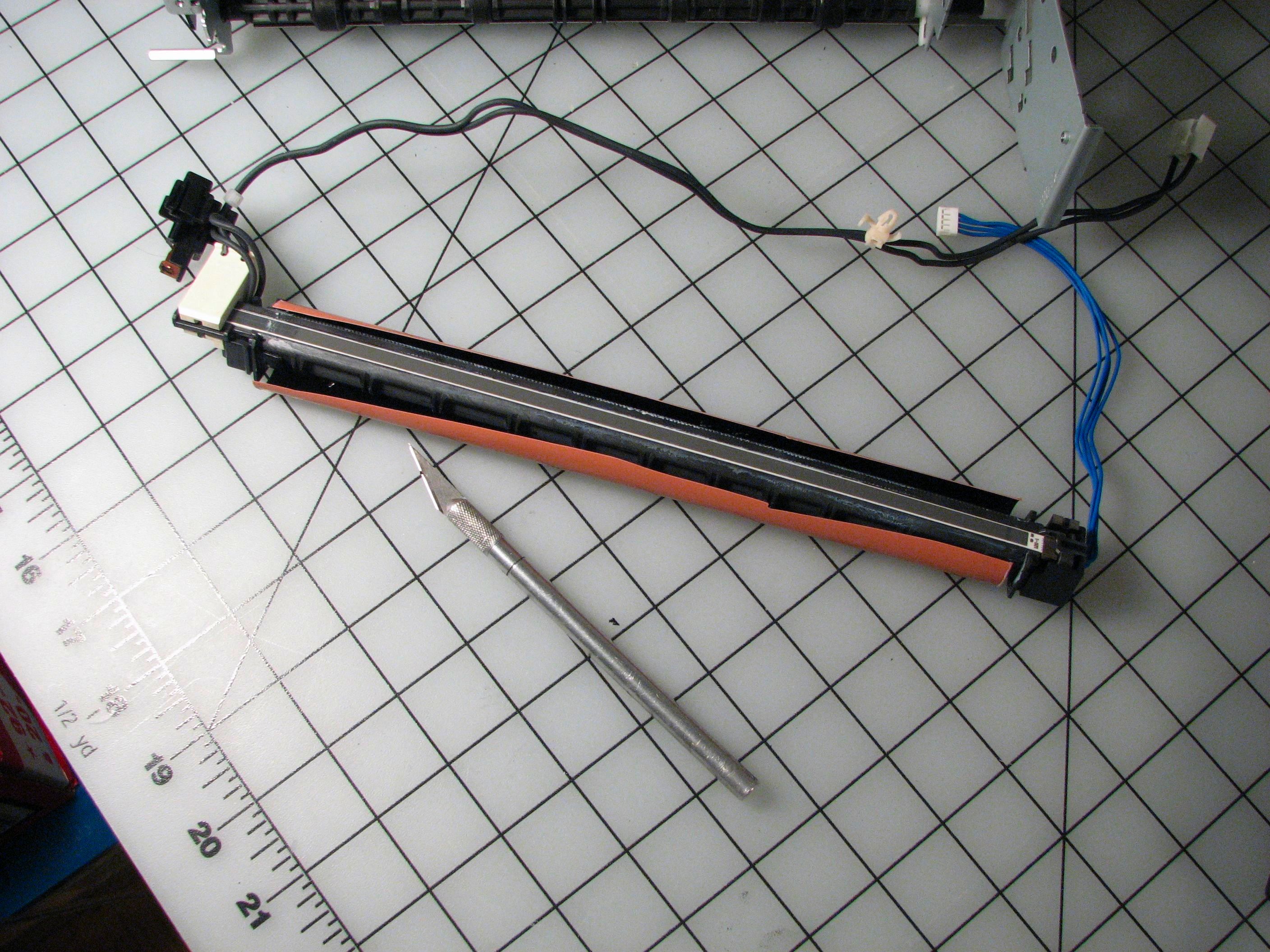
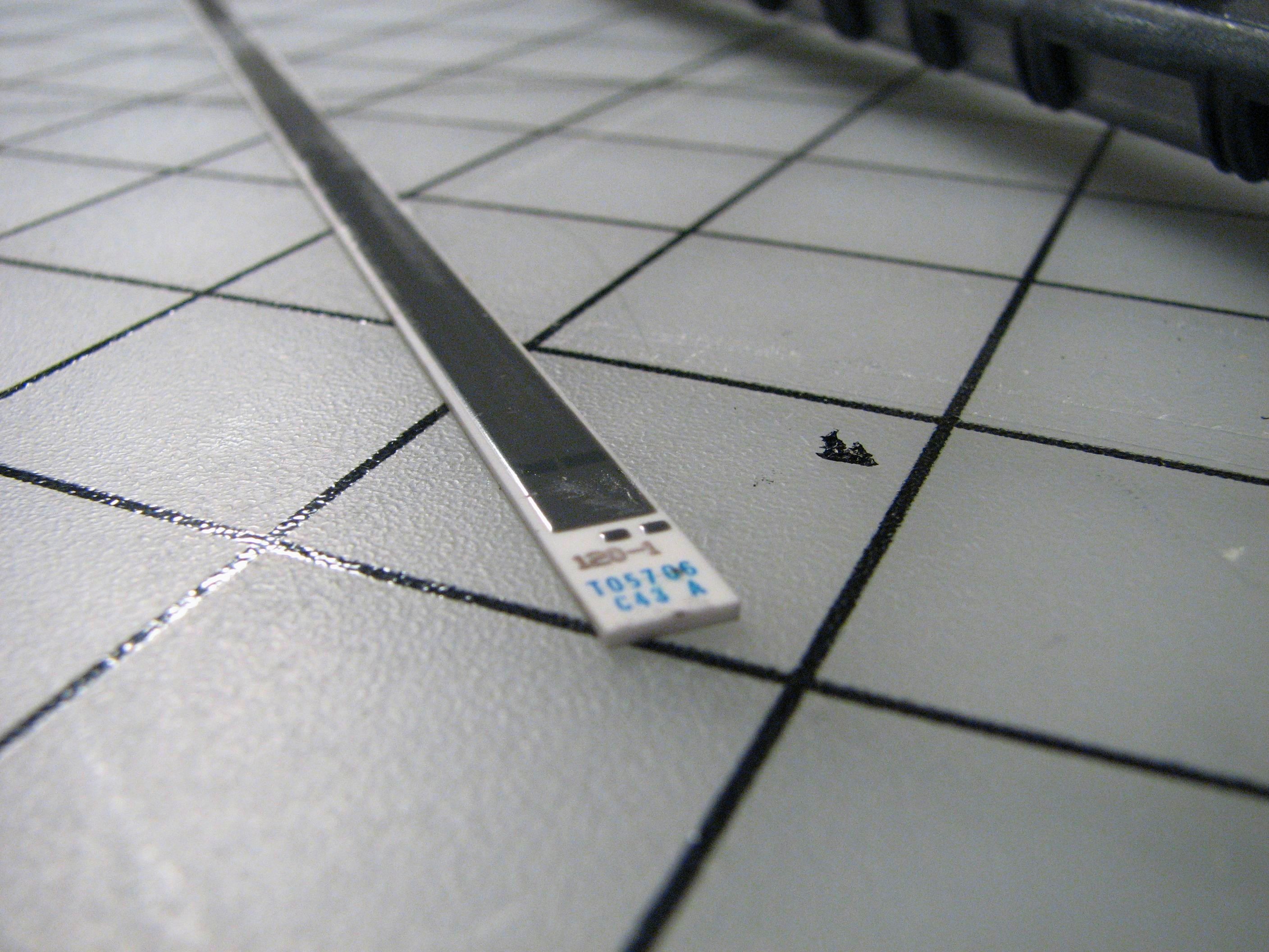
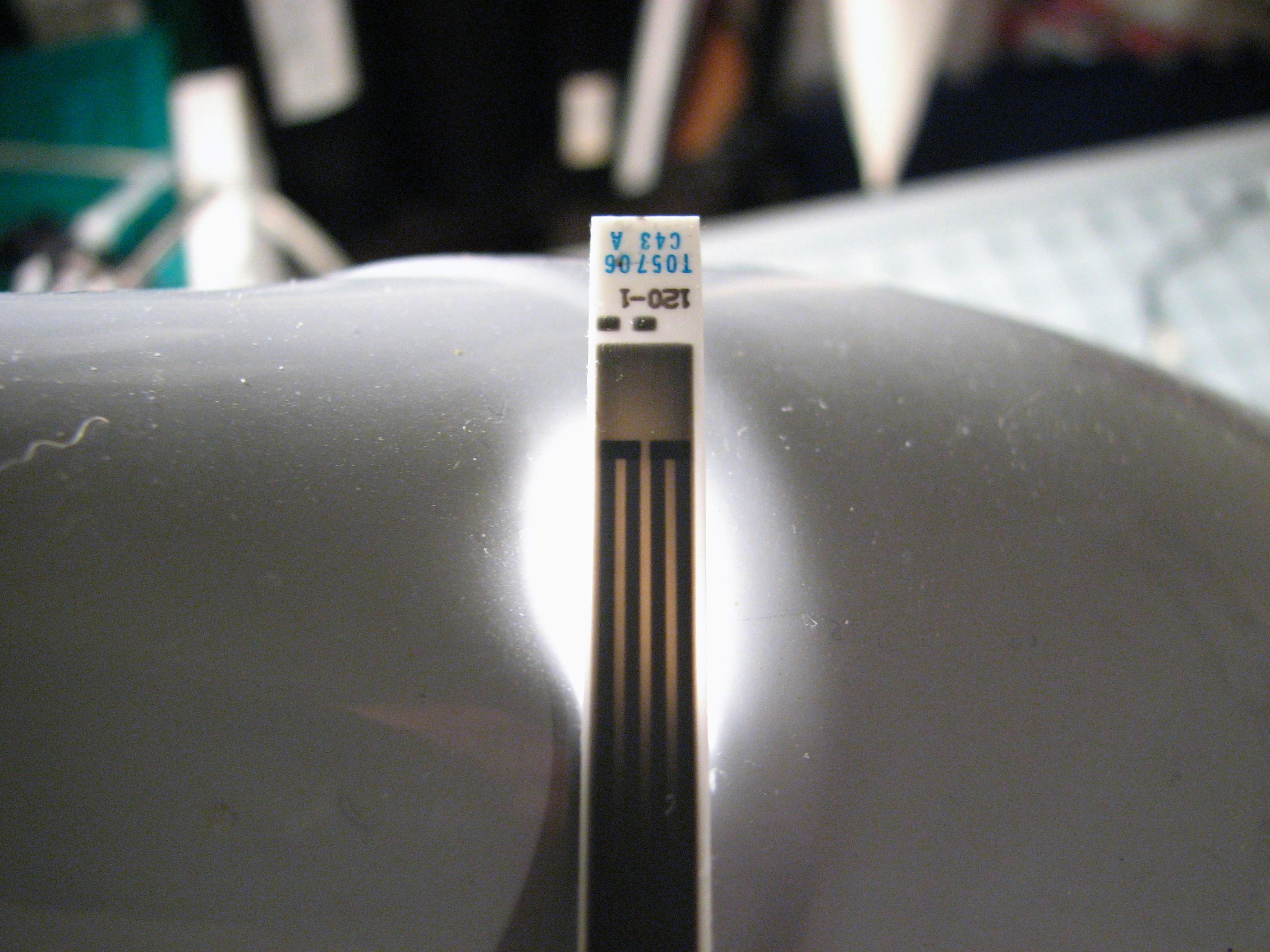
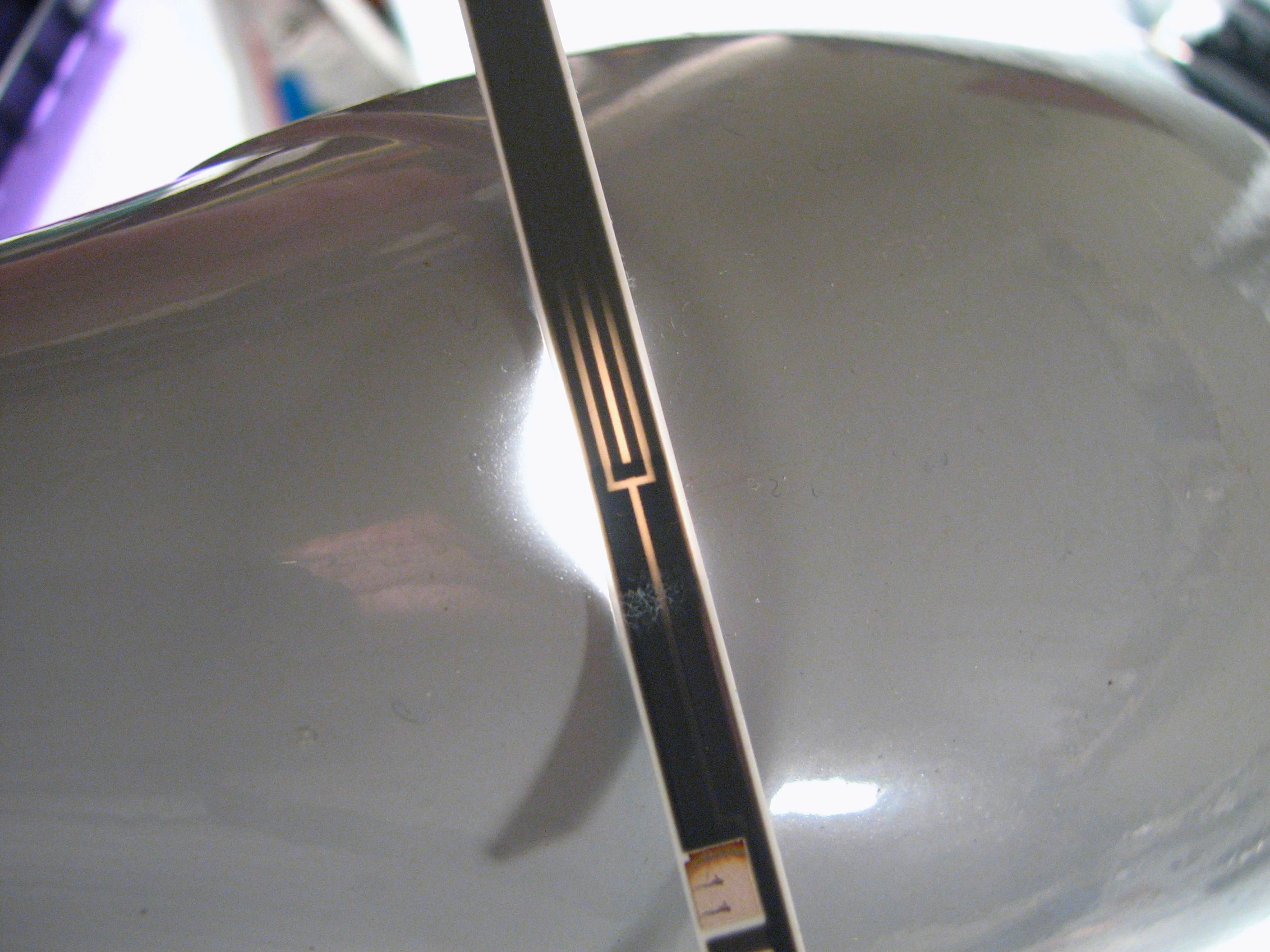
The heating element for the fuser is actually a ceramic thick film resistive element. It’s wider than a sheet of paper, about 1/16″ thick, and about 1/4″ wide. If you put it up to the light you can see that the resistive track through the heater winds down to the end and back twice. Also in the orange roller next to the heater is a garden-variety thermal cut-off fuse and a pair of temperature sensors.
There is one last circuit board inside the printer. This one is also hidden back behind the toner cartridges, and in fact, it’s the interface to the cartridges. If you notice, there’s an LED that points into the toner cartridge and a phototransistor that reads the transmission through the cartridge. This is only to detect if the toner is empty– As part of the ink-selling mission of this printer it cannot detect if the toner is full; the yellow cartridge is empty after 2000 pages, whether you used any yellow or not. (Slimy, isn’t it?) There’s also a two-pin electrical interface talk to the cartridge; I’m not entirely sure all of what it does. Surely part of it is maintaining the internal page counter.
And finally, what is left of our once-proud printer? Not much. Just a few sheets of steel.
Before we wrap it up, we have some notes about the design. One of the remarkable things about this teardown is that absolutely zero wires and zero cable ties needed to be cut to disassemble the machine as we have done here. Rather, the wires are arrayed in carefully designed harnesses that terminate in connectors– usually on both ends. The wire bundles are also neatly organized in how they thread through the machine. If you’ve taken apart other instruments, you’ve probably come across cable ties that had to be cut in order to pull the wires or wire harness out. Most of the wire routing here is done by wrapping the bundles around engineered obstacles and loops. In several places there are even complex molded pieces that serve no purpose other than to guide and confine a wire bundle without the need for additional fasteners.
This is actually typical of the fine engineering found throughout this machine– every piece has been carefully planned as an integrated system. Many of the metal parts fit together like jigsaw puzzle pieces, clearly designed to mate against each other, and designed to allow disassembly. There are a couple of interesting design choices– like using a larger number of flat-ish sheet metal pieces to form the frame rather than one (or a few) larger pieces. It’s also surprising to see the sheer number of custom molded components that are used in this machine. Many of the parts are designed to accommodate the other variations on this platform– with attached duplexer, scanner, or lower-end configurations without networking.
Overall, you get the sense that this was designed with a very high set of engineering and tooling costs, intended to be recovered over many years as a low-cost mass-produced machine. They seem to be succeeding.
Now, let’s see how we did on the scavenging agenda. Here is a list of some of the possiblly useful bits that we pulled out:
- Machined metal scanning mirrors on high-speed brushless motor drives with aluminum circuit boards (2)
- Infrared (?) laser diodes (4)
- “Interesting” photodiodes. (2) ( My guess: position-sensitive types)
- 12+ photodiode/photosensor pairs. 7+ standard photointerrupters, and others
- One humidity sensor
- Stepper motors (2)
- 9″ x 1/4″ high-temperature thick-film ceramic heater
- 2.5″ x 3/8″ first surface mirrors (4), presumably for IR
- Precision molded plastic aspheric lenses (10)
- Glass lenses (4)
- An “outrunner” style brushless motor
- Solenoids (3)
- A microswitch with a long lever
- Three microswitch buttons
- Plastic gears — dozens.
- Garden-variety computer fan
- High-voltage capacitors and transformers
- Heat sinks
- An LCD display
- Precision ground shafts
- A thermal cut-off fuse
- Temperature sensors
- Anti-backlash gears
- Funny shaped cams
- A giant pile of phillips head screws
- Lots of wire in neat bundles
- Other circuit boards filled with of interesting components
Not bad for an almost-free printer!
So if you want to take one of these apart, what’s the best way? Find one that someone else isn’t using any more. Reuse and recycle! Because of the relationship between the retail price of this printer and the toner price, it’s usually pretty straightforward to find one or more of these available on Freecycle, Craig’s List, or eBay for free or just shipping costs. Better for you to take one apart and use the parts than that it just goes to the dump.
Or, you can just buy one and use it as a printer… until it reaches that magic page count in the sky.
nit picking: it looks to me like the LCD has a chip-on-glass controller (only ~15 connections to the PCB for a dot-matrix LCD), which means that the chip on the back of the PCB does something else.
So does anyone want to buy an old 2600n with no cartrdiges? I did the non-environmentally-friendly "replace the cartridges by buying a new printer" (actually a 2605dn, so it’s an UPGRADE) deal, moving what was left of the cartridges into the new printer (where they lasted quite some time, despite not being recognized as genuine HP cartridges…) Sigh.
Indeed. I’m not quite sure what it is. My searches didn’t turn up any definite answers, but I suspect that it’s made by Rohm and it certainly has many of the characteristics of an LCD driver.
—
Windell H. Oskay
drwho(at)evilmadscientist.com
http://www.evilmadscientist.com/
As an electronics recycling company, I commend you for showing the fun part of destroying machines. This was a fun read.
You said something about using slots to increase isolation on the high voltage board. Does that really work? Does air have a higher resistance / breakdown voltage than circuit board material?
Yes, it is actually one of the standard techniques used by people who build high-voltage circuit boards. You can see another example of such described here.
—
Windell H. Oskay
drwho(at)evilmadscientist.com
http://www.evilmadscientist.com/
On the slots in the PCB….
Contamentation like dust or mositure can build up on the PCB. That provides the conductive path for arcing to start. By cutting the slots in the PCB you don’t give that stuff a place to rest. (Unless it’s really packed with dust.) So it’s not really about which is a better insulator air or PCB. You’ll also see this in some power supplies under the optocoupler. They need to isolate the AC line from the output. Seems like they need 2000V isolation.
Hi windell, arkaoss from Candyfab here. I am interested in getting ahold of that Ceramic filament to attempt a candyfab heater design. If you need my Email, , its Pk att phillk dooot net
Say, want a TGIMBOEJ? Hint hint….
—
Windell H. Oskay
drwho(at)evilmadscientist.com
http://www.evilmadscientist.com/
That was far more interesting than I expected!
I know with some of the B&W laser printers I’ve owned, the original toner cartridge has only a fraction of the capacity of a replacement cartridge, which could help explain the price discrepancy between a new printer and new set of cartridges.
I was unclear how you determined the yellow toner is always "empty" after 2000 pages. If it was a hardcoded page count, then why have a toner sensor for that cartridge? Maybe I misunderstood something.
Is this one of the models that prints a pattern of yellow dots in order to track counterfeiting? I wonder if that’s why the yellow cartridge is treated special.
Had you ever tried printing an image of US currency on this printer in order to determine if it has anti-counterfeiting measures built-in? Or is that only in scanners? It would be interesting to identify the circuitry responsible for that.
>I know with some of the B&W laser printers I’ve owned, the original toner cartridge has only a fraction of the capacity of a replacement cartridge, which could help explain the price discrepancy between a new printer and new set of cartridges.
That is indeed the case for the low-end model, the Laserjet 1600– it ships with "half capacity" cartridges. One of the advertised points of the 2600’s is that they do ship with full toner cartridges.
>I was unclear how you determined the yellow toner is always "empty" after 2000 pages. If it was a hardcoded page count, then why have a toner sensor for that cartridge? Maybe I misunderstood something.
Comes from a little Google searching. It’s apparently confirmed by multiple people and even HP reps. The sensor is there so that if you *actually* run out of toner, it will tell you.
>Is this one of the models that prints a pattern of yellow dots in order to track counterfeiting? I wonder if that’s why the yellow cartridge is treated special.
It does indeed have the pattern of yellow dots. See Bunnie’s blog entry about the controller circuit boards that I linked above– he was investigating the yellow dots and that’s why he was in the printer. The yellow *is not* special. The same limits apply to all four cartridges (2500 page limit for black).
>Had you ever tried printing an image of US currency on this printer in order to determine if it has anti-counterfeiting measures built-in? Or is that only in scanners? It would be interesting to identify the circuitry responsible for that.
Nope, haven’t tried. Might be interesting.
—
Windell H. Oskay
drwho(at)evilmadscientist.com
http://www.evilmadscientist.com/
I think the anti-counterfeiting measures are built into the currency (microprint strips, two-tone inks, etc.) not the device. You might be thinking of Photoshop – it apparently has a few hax against banknote scanning. But the currency itself is the first line of defense.
@rfordh: I’ve seen quite a few instances where a PCB has slots cut into them for isolation, I just checked my junk pile and 2 HV cold cathode inverters have a slot, one ghetto laser printer, one DVD player power supply board, and one dead ATX power supply. The DVD player and ATX power supply both have optoCOUPLERS situated over this gap, presumably the design was that a large jump in voltage won’t be able to arc across.
And I recall seeing something similar in an old UPS I scrounged where the MOV’s (surge dissipation) had slots underneath them
Humidity is important if there’s any kind of static charge involved in printing.
I worked at one place where we had a 36-inch electrostatic plotter. Part of my job was to ‘water’ the plotter every morning: put a layer of paper towels on a bar under the paper roll and pour water on it. With normal humidity, we could get good plots all day. In dry weather, it would need more water around 2pm.
(This reminds me of helping a friend to disassemble a couple of copiers. The good parts got saved; the rest went into the recycle bin.)
An old maxim:
Do not look into the laser with your remaining good eye.
I recently investigated the two-conductor interface with the cartridges on a Lexmark color laser printer. The IC in the cartridge turned out not to have a standard part marking, but was the equivalent of a Dallas Semiconductor DS2431 – a 1024-bit EEPROM chip with a one-wire serial data interface.
Emptying the contents of this chip revealed a string identical to the serial number from a label on the outside of the cartridge, a type identifier and other unknown data.
Incidentally, Lexmark seems to use similar dirty tricks in their cartridge management – after a certain amount of time the printer will simply reject the cartridge, and "starter" cartridges that ship with a printer are locked so they will only function with that specific machine. I would not be at all surprised if the planned cartridge death is based on some sort of hardcoded page count.
That’s *very* interesting. Suggests that you could read out the contents of a new cartridge and rewrite them later to trick the printer into thinking it’s still new.
—
Windell H. Oskay
drwho(at)evilmadscientist.com
http://www.evilmadscientist.com/
Cartridge world in the UK refils lexmark *toners* for the fraction of the price of a new one. I tried them once and when I attempted to use it the first time it failed – they came out and replaced the PCB exposed on the outside of the toner (one screw). Problem solved. The replacement PCB just had an 8 pin 16F series PIC microcontroller onboard – presumably they can reuse these (and also possibly fix the page count even lower).
As a matter of fact, that’s what I plan to do tomorrow. We’ve just received a whole batch of fresh cartridges, and along with the data from the four that are in the printer now I hope to be able to isolate the bits in the EEPROM memory that tell the printer to reject the cartridge as being too old.
Would love to do this to my Konica-Minolta 2400W but since I worked for Xerox for 10 years, I don’t really have to… FYI, do you know that a laser printer uses what is called "write white" principle: On a normal photocopier, the paper is charged with a uniform static charge (hence moisture is important – too humid creates blank spots, too dry might create dark spots – then exposed to reflected light so all that is "white" is discharged, leaving only the "positive" dark image we want to print. On a laser printer, the laser does the same thing: discharge the wite areas, meaning that the laser do not write "the text" but erases everything around it.
For counting the copies of toner cartdriges, my K-M printer uses DS2432 chips, which are one shot programmable counters. I read that there’s a lot of pressure against the company that makes them, stating that they "forces" throwing cartridges in the landfills instead of recycling them. Their answer: we only make the chip, we’re not responsible for what other companies do with them…. Makes me think of tobacco companies…
You can buy new chips with toner refills.
– Pierre.
Any idea why I keep getting a black line down the middle of my print-jpbs? I can wipe off the resin on the filament, however, it reappears and leaves the black line on all print jobs. I have cleaned system back to back to no avail. Any suggestions would be appreciated.
kn
i ended up on this site cause i am trying to fix an hp2550 colour laser can you guys show something on it, the way you did here was great wish the net was always like this also anyone with something on hp2550 email me tapiwatech@gmail.com.thanks guys
yes, I am interested……how much and does it work?
You are not alone! I also stripped my 2600n down for fun and salvaged all the goodies. I don’t know what I am going to do with all the gear wheels but I just can not throw them out.
Karl.
give the gears to TGIMBOEJ
My daughter used plain paper in this unit and now I get wrinkles at the bottom of every page. What do I look for or what can I do to fix this issue?
My technician husband saw your guide and it brought him much happiness! Much respect to you. I’m having ghosting problems with our business 2600n and your guide, along with a new fuser roller I’ve found on eBay, are going to be our saving grace!
I think the sensors behind the belt are used for calibration. The printer "prints" blobs of toner onto the belt by doing a normal print but without paper. In can then use the sensors to see how dense the blobs to calibrate itself. Dunno if it also senses position, but I guess it could.
Very interesting.
just yesterday, I also tore open my old 2600n, It stopped printing red and yellow a couple of years ago, and it was just lying around..
I had free time (and a new printer so i dont care about this one). so I decided to find out what went wrong. I read somewhere that this printer has a common problem in which dust leaks into the mirror-lens box and blocks the lasers. I opened it and cleaned it with cotton buds + air spray, and now it’s as good as new! (I’m thinking of refilling the toners now, because it turns out you can override the EEPROM warning on this model).
Thank you for the interesting read.
i believe i found the data sheet for the humidity sensor. link is bellow
http://www.szhdk.com.cn/downloads/2007618164231.pdf
More slots on PCBs found in this teardown of a mobile credit card reader video.
The slots in this case are thought to be for isolation of a modem interface as well as for mechanical reasons.