


Nothing makes us more gleefully happy than taking things apart. On the table today: a pedometer. Lots of gory pictures after the jump.

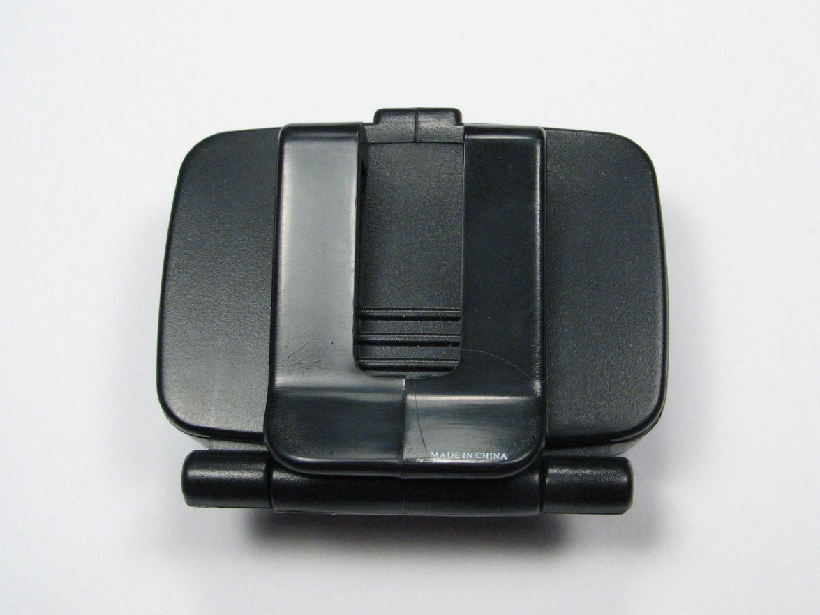
I put a sticker on my pedometer to hide the corporate logo. The hinge is in a funny place – it opens downward, which was never what I expected. It clips onto your waistband and when you open it up, you can read your step count. It always seemed upside down to me unless I was actually wearing it.
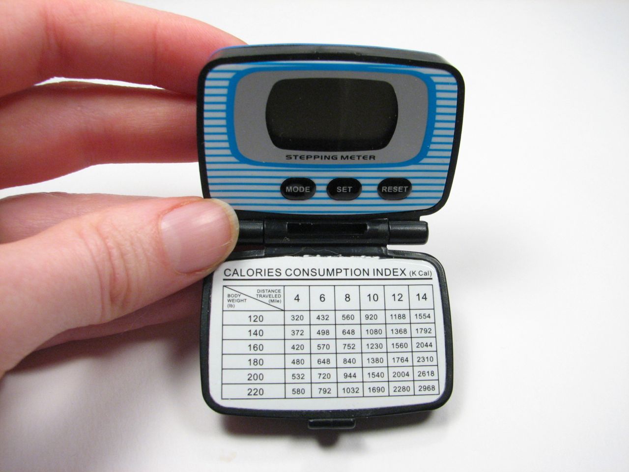
It came with two stickers to put on the clip side of the plastic body – one metric, the other “standard.” I didn’t pay much attention to this “calories consumption index” since I was only using the pedometer for a walk-a-thon. The walk-a-thon is over now, so let’s take apart the pedometer! 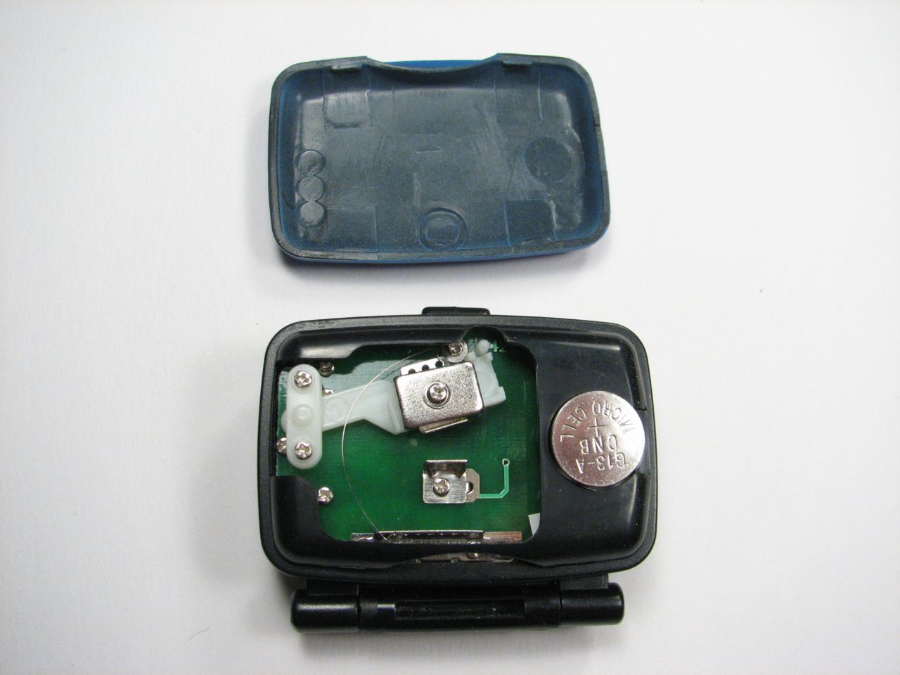
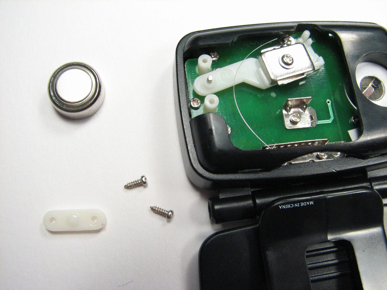
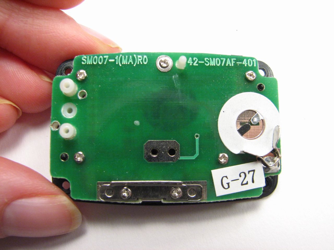
Step one: pop off the battery cover. Needs a quarter and a lot of force. As you walk, the arm swings down. When the arm hits the bracket, the count is increased. The itty-bitty thin wire spring pulls the arm back away from the angle bracket. 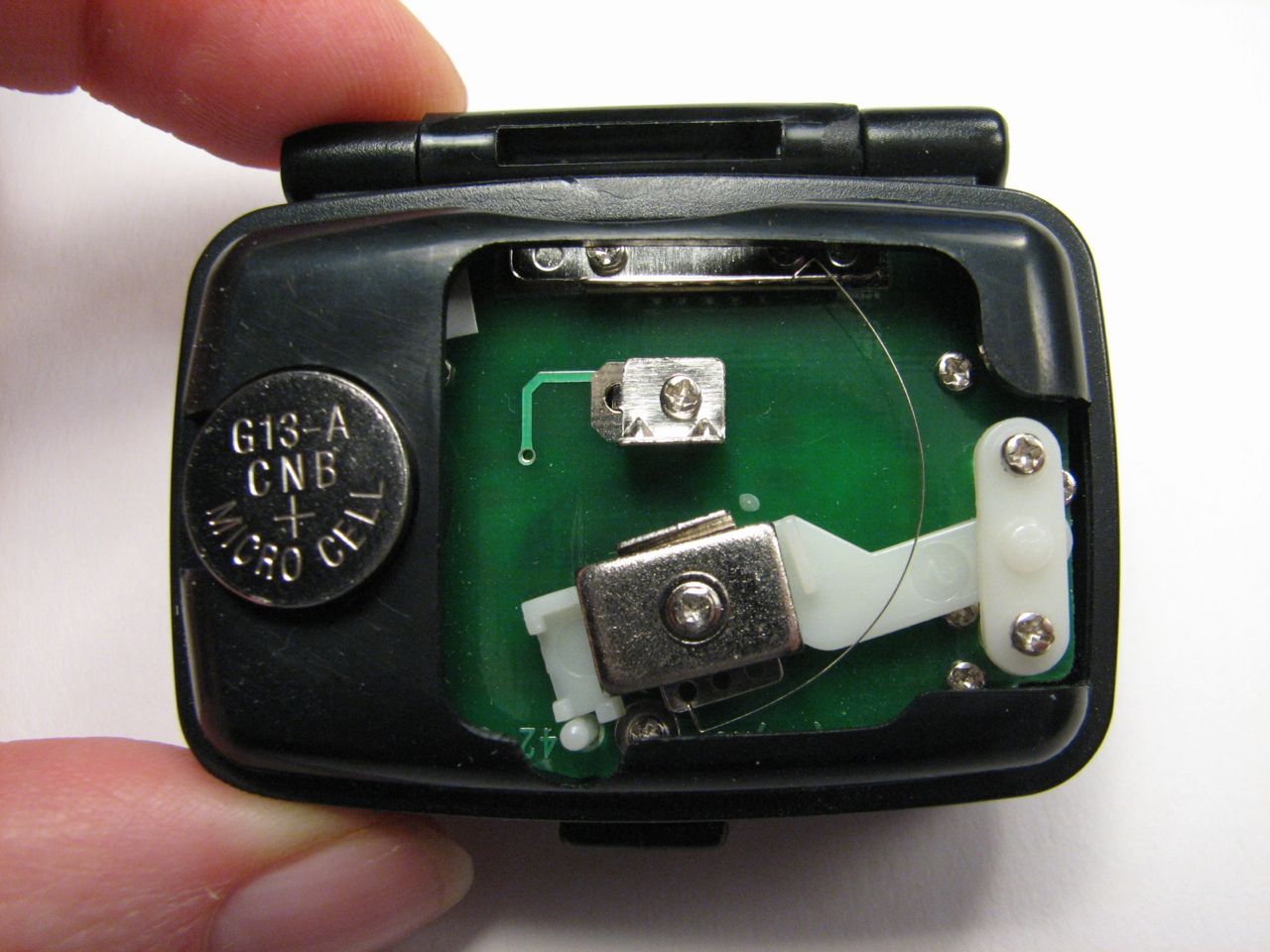
In these pictures I’m actually holding it upside down – the hinge should be on the bottom. You can see how when the arm swings, the circuit is connected via the spring and the metal on the arm. Okay, enough of how it works– lets get back to taking it apart!
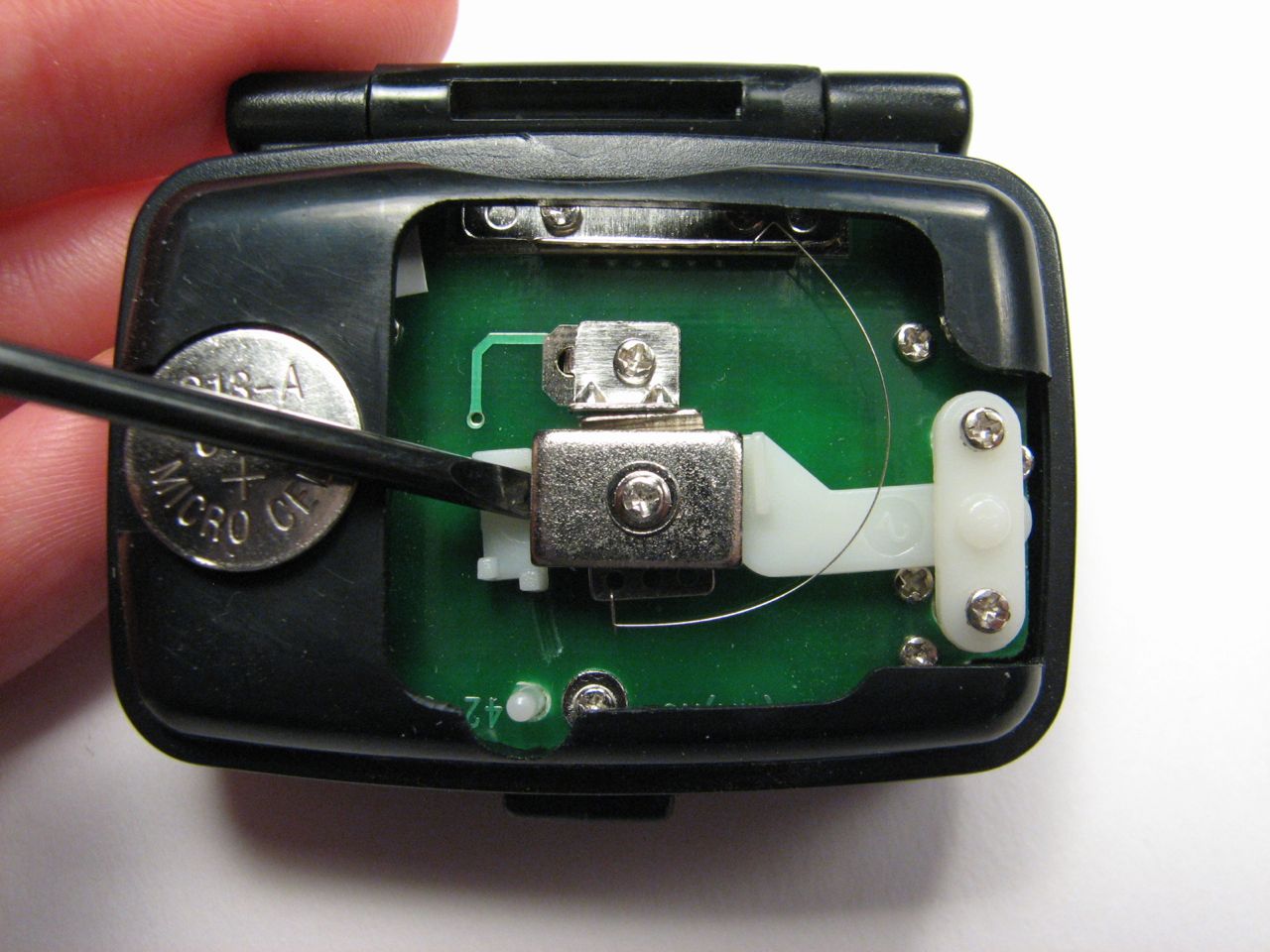
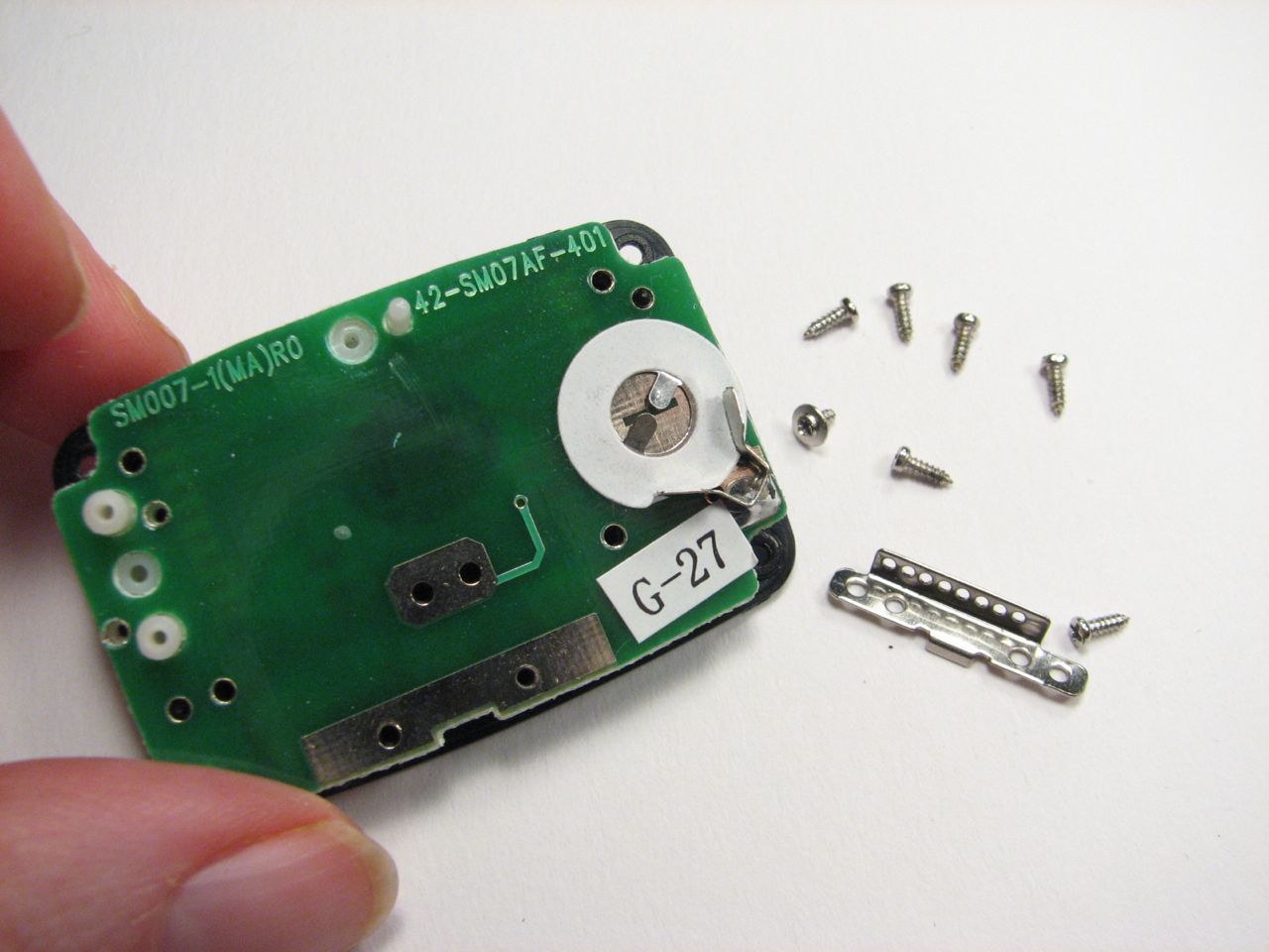
Step two: remove battery and screws holding the bracket for the swing arm.
Step three: unhook spring and lift out swing arm. The arm rotates on a metal rod, which will come out now, too.
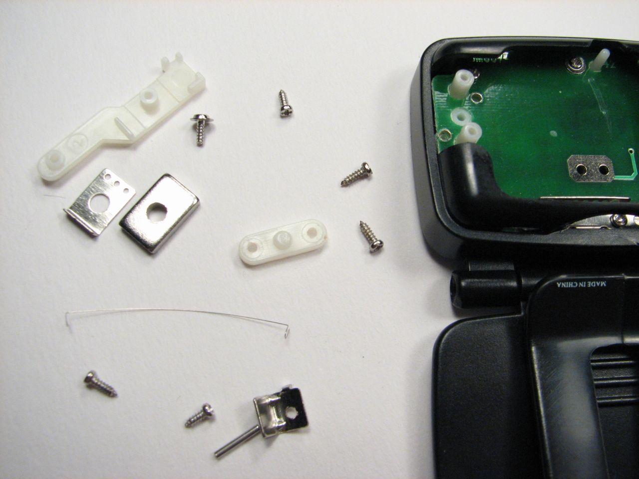
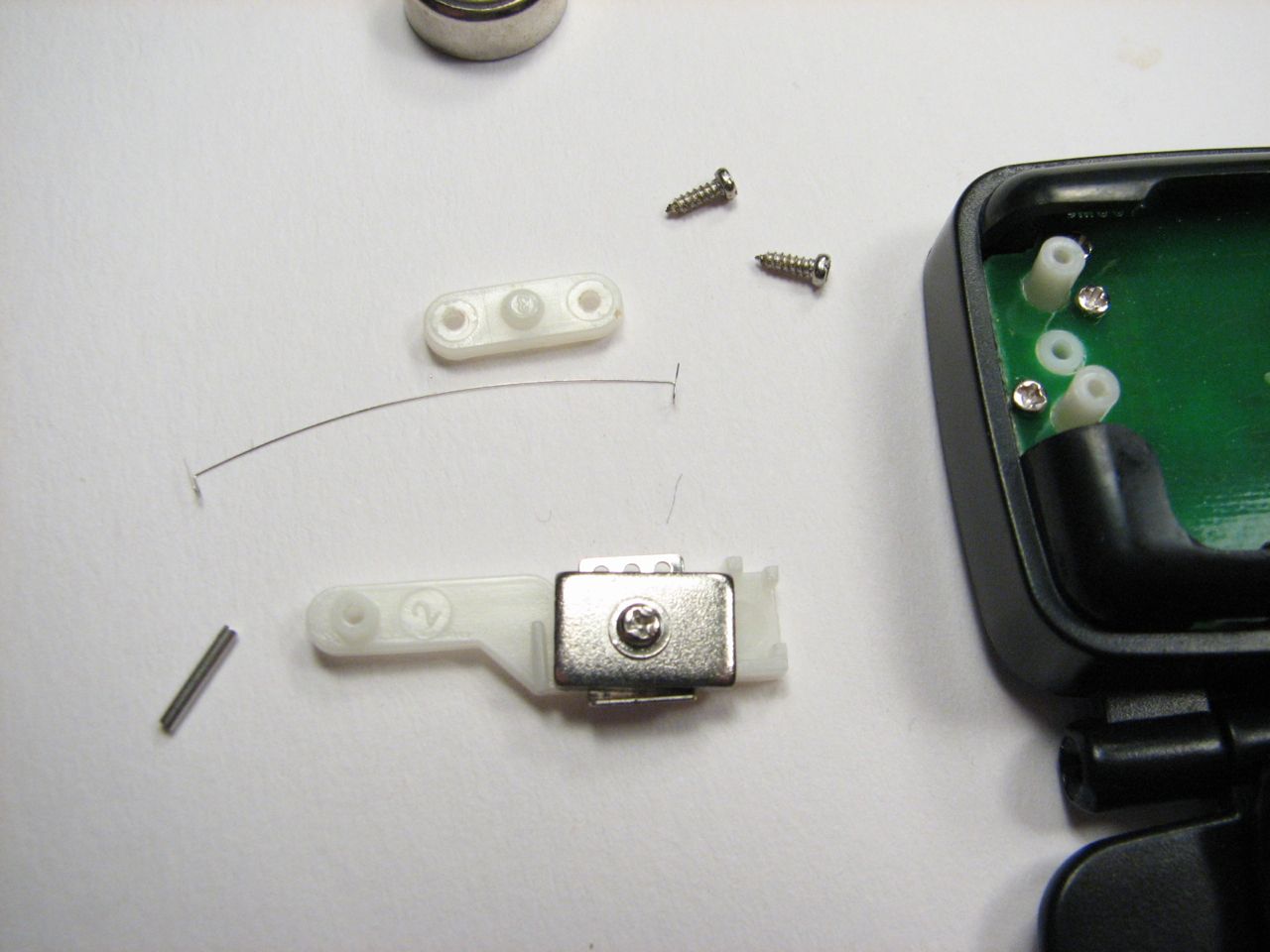
Step four: Take the weight and angle bracket off of the swing arm, and remove angle bracket from circuit board. Also remove two more screws which have become accessible. That’s all we can get at from this side for now.
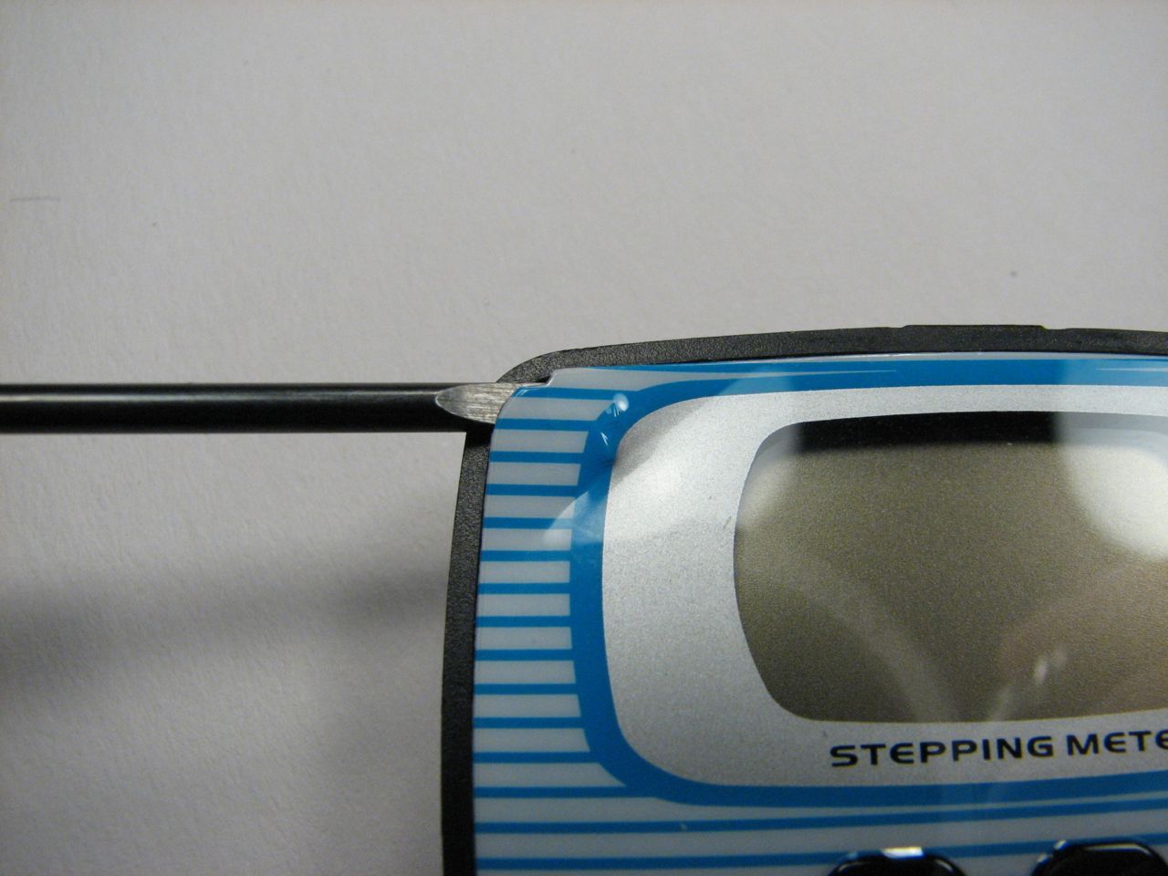
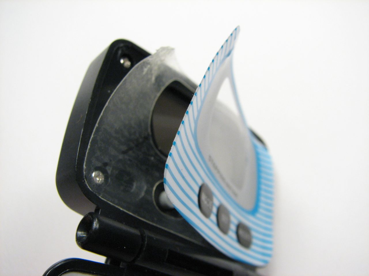
Step five: pry off the face plate. The face plate cover is secured with a layer of serious adhesive. Both peel off pretty easily once you get something like a screwdriver under the edge.
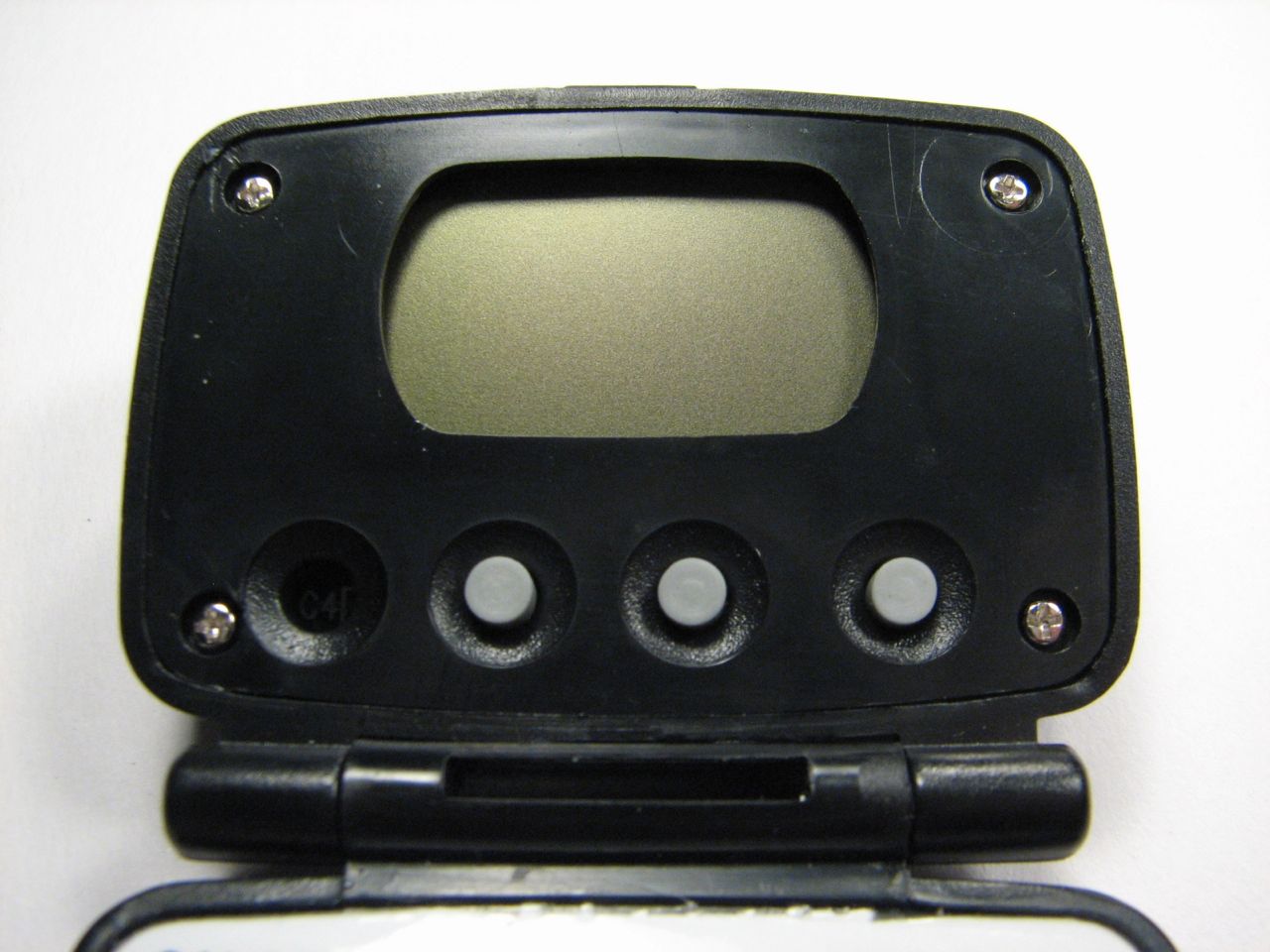
The face of the pedometer now looks much better – rather like something out of Star Trek. It has lost its corporate give-away feel.
Interestingly, there is a hole for an extra button. There must have been a redesign somewhere along the way.
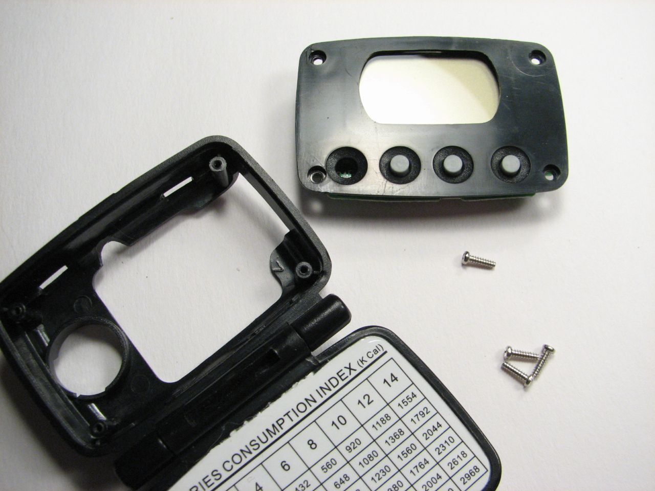
Step six: remove the four now-accessible screws and the rest of the shell will come off. Flip it over, and seven more screws are accessible now!
Step seven: remove seven more screws. The angle bracket that the spring hooked onto will come free now.
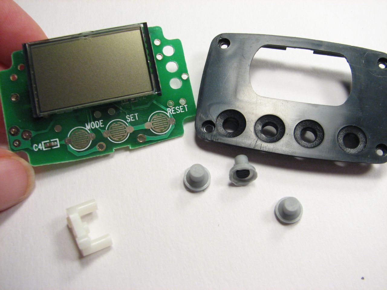
Step eight: pull apart the face plate from the PCB. The buttons will come out now, as will the plastic bracket that held the pin for the arm.
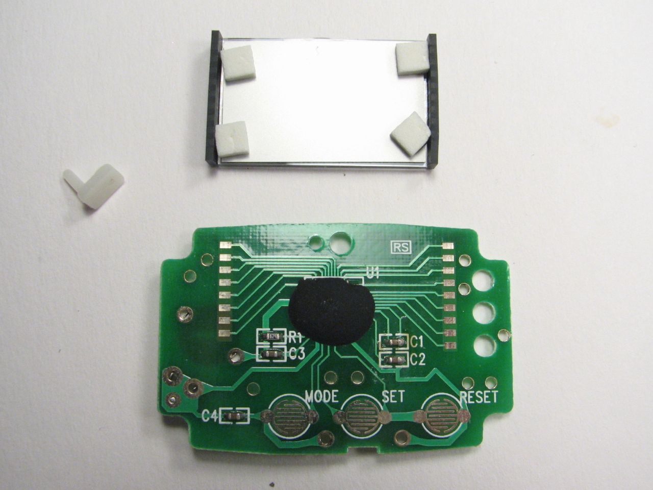
Step nine: pull the LCD away from the PCB. The piece of plastic that stopped the arm from swinging will come out now.
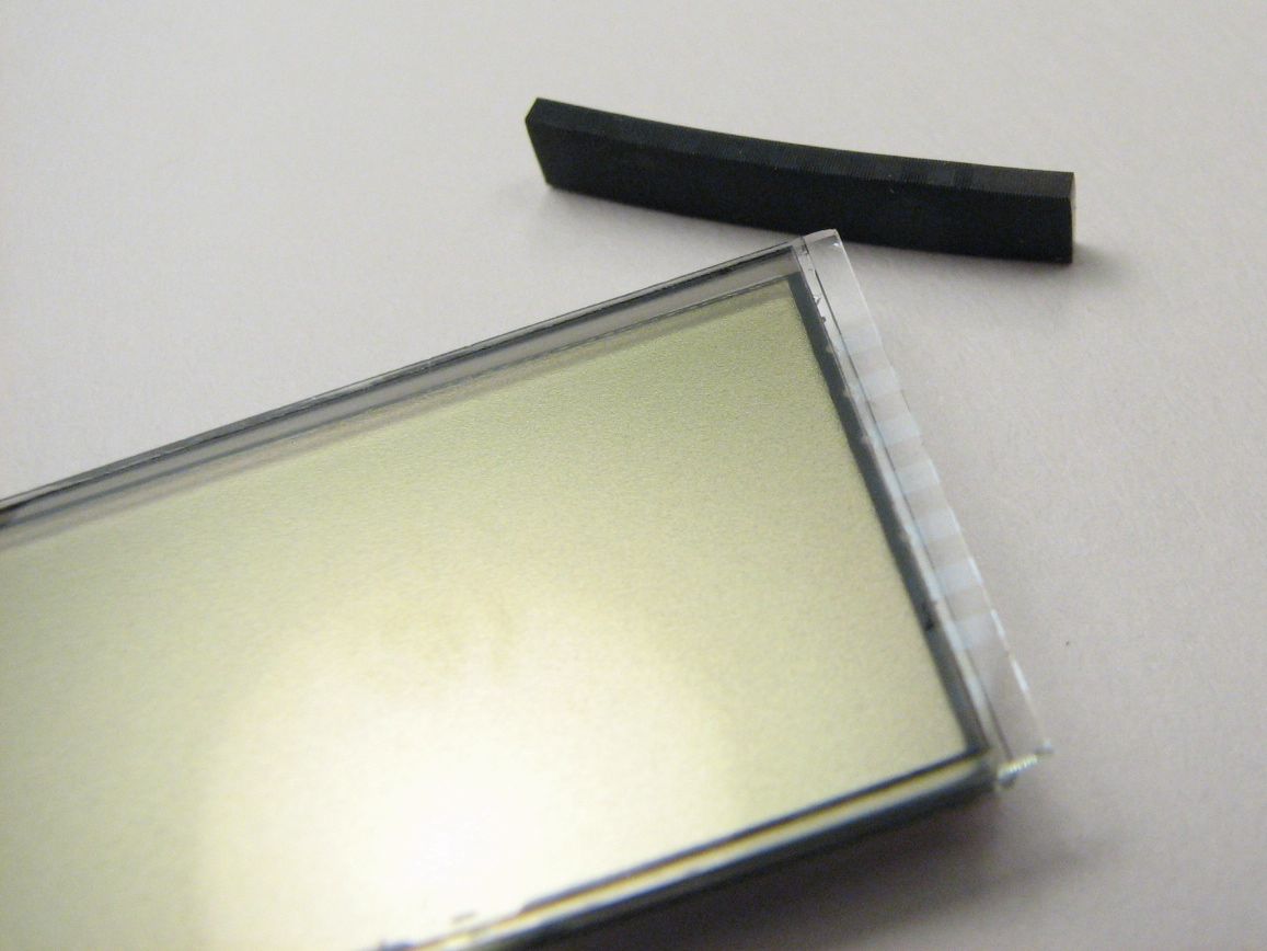
Step ten: pull the rubber connectors away from the LCD. Check out the stripes on the connectors as well as on the LCD! The don’t look much like wires, do they?
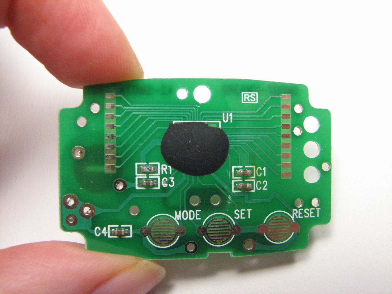
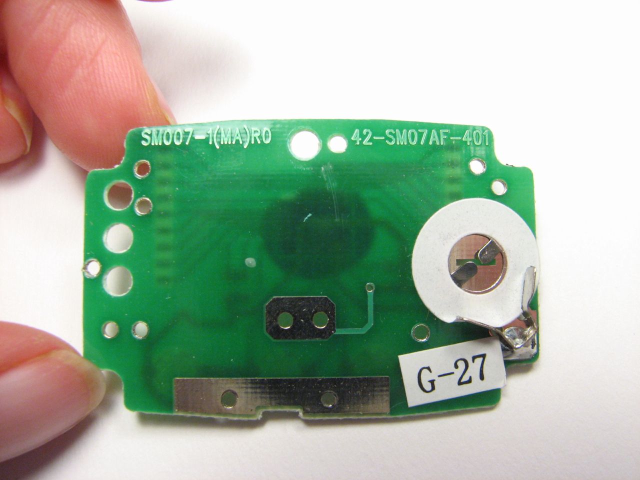
The PCB is rather cute. I like how well labeled the buttons are. Only one more thing to remove…
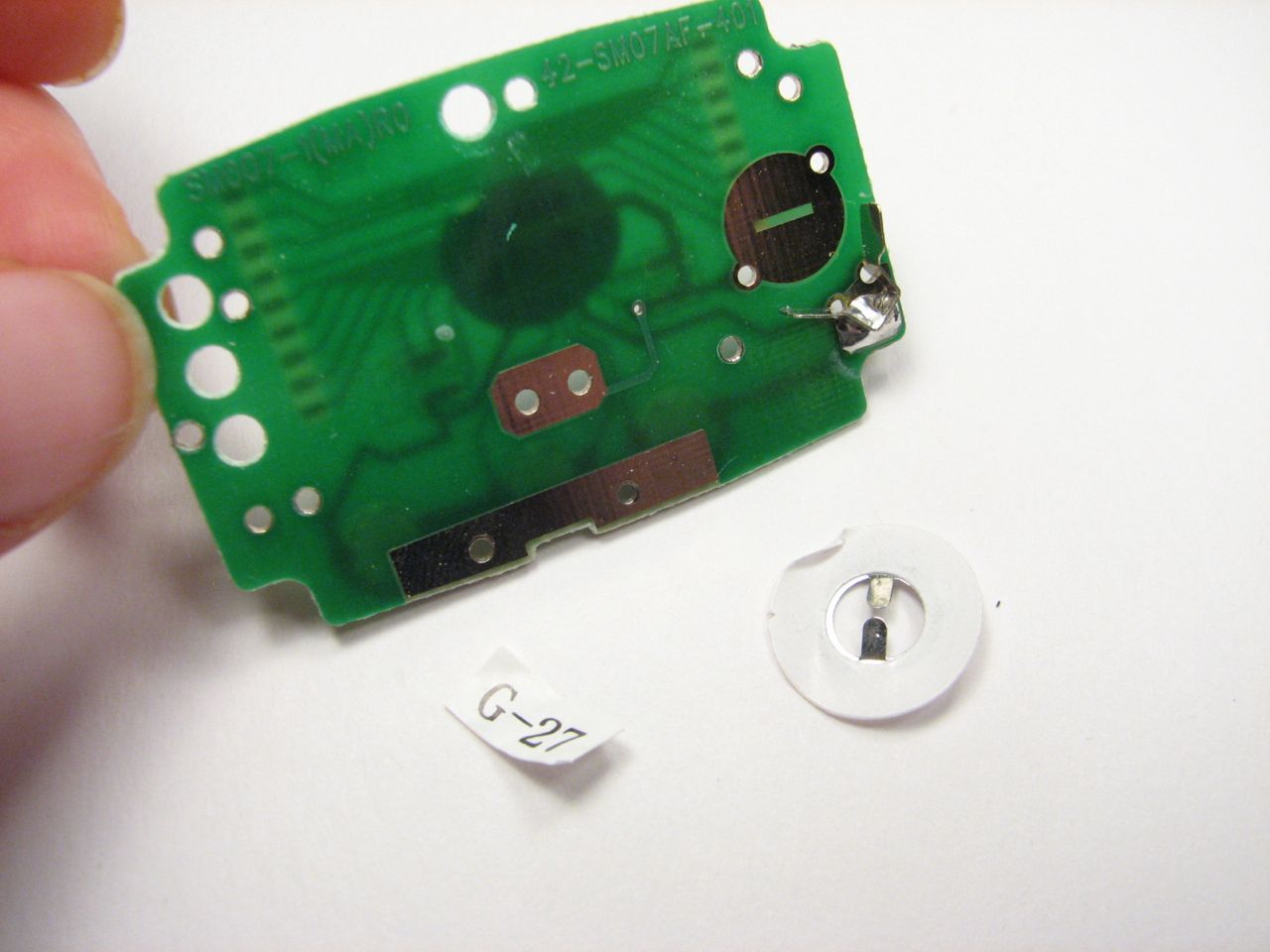
Step eleven: remove the battery spring. The spring, which is just stuck on, pops the battery up for easier removal and replacement. It also guarantees a reset when you open the case, since it disconnects the battery.
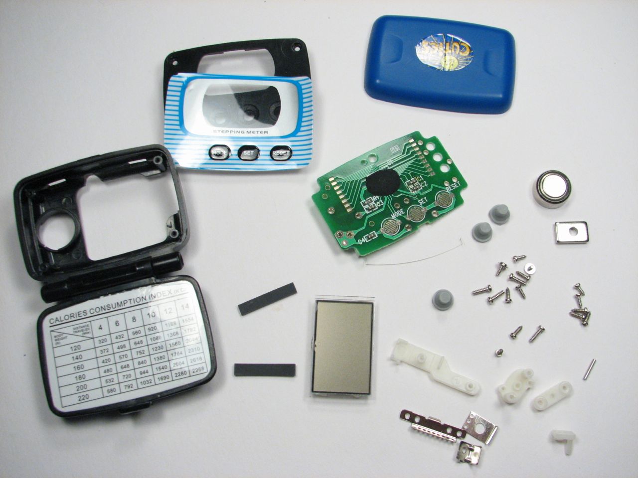
Here are all the parts: 1 PCB, 1 weight, 1 pin, 1 wire spring, 1 battery, 1 adhesive spring for the battery, 1 piece of adhesive, 1 plastic faceplate cover, 1 plastic faceplate, 1 hinged case, 1 back cover, 1 LCD, 2 rubber connectors, 3 buttons, 3 angled brackets, 4 plastic arm assembly parts and 17 screws (of four different types).
I didn’t count the individual parts on the PCB, since I didn’t desolder them. I don’t have much use for surface mount resistors and capacitors, and they look cute where they are. But all those screws…I had no idea you could fit seventeen screws into a case that small. Or that you would want to. Interestingly, many of those screws were used to secure electrical connections between the angle brackets that connected the arm assembly. It is certainly fun to see how the mechanical interacts with the electronic. Even the wire spring was a part of the circuit.
I even get broken electronic/mechanical equipment from the dump so my kids and I can take it apart. Hmmm…I wonder if there’s an video game concept there. Sort of an anti-Grow thing.
Do you know if there’s any way to reuse those LCDs with the stripe connectors? I keep finding them in stuff but have no idea even what to google for, let alone how to use them.
Yeah those LCDs with the funny connectors have had me wondering too. I guess that foam stuff is conductive? What’s it actually made of? Any easy way to reuse them?
Yes, the foam is conductive, or at least the dark stripes embedded in it. But looks like it usually needs some pressure to make it connect the LCD module to PCB. I suppose this is another reason for the metal shields enclosing LCD and that conductive rubber connections.
They are called zebra strips.
I think technical term is elastomeric connector.
One thing I noticed is that to make contact using those requires al teast little pressure along the strips.
very interesting, I got a Pedometer laying around, you ought to figure out a project of something nifty to do with the pedometer once it’s taken apart!
the mechanical parts could be used as a ‘binary’ accelerometer– mounted in the proper position so that a particular motion causes it to ‘fire’, it could be used to count how many times a door was opened, or when a car stops and starts (at traffic lights for example). Similar to an old mercury switch (that you can find in old thermostats), it can be used to determine whether the +/- acceleration of an object changed (at least enough to move the little weight). Messing with the mass of the weight and/or spring would conceivably make it more/less sensitive.
That is percisely the type of application that came to my mind. I would make a magnetic pedometer refrigerator (MPR) door counter. I would market it through Jenny Craig in double packs. One for your foot and the other for your refrigerator. My infomercial would double the number of MPRs for the same low price of $29.99. People could place these things on all doors leading to food and see which cabinets, refrigerators, pantrys and desk drawers get the most action by the food enthusiast. I would make millions and millions of dollars. Retire early. Start my own Mad Scientist Blog. Life has so much potential.
Wire an external button or switch of some type in place of the swinging weight
and you can use the pedometer as a digital event counter.
Quite obviously the 4th button, if you look at the label, was an early-developement plan to sell these to suicide-bombers. Push the C4 Button and the little guy explodes.
maybe there is a way to use the body of the pedometer as a led flashlight case and use one of the little buttons as a switch
just an idea what ya think
Great. Now how am I going to find pedophiles now?!