


Well, almost— With a breath of new firmware, our Larson Scanner kit takes us on a trip to the late 1970’s.
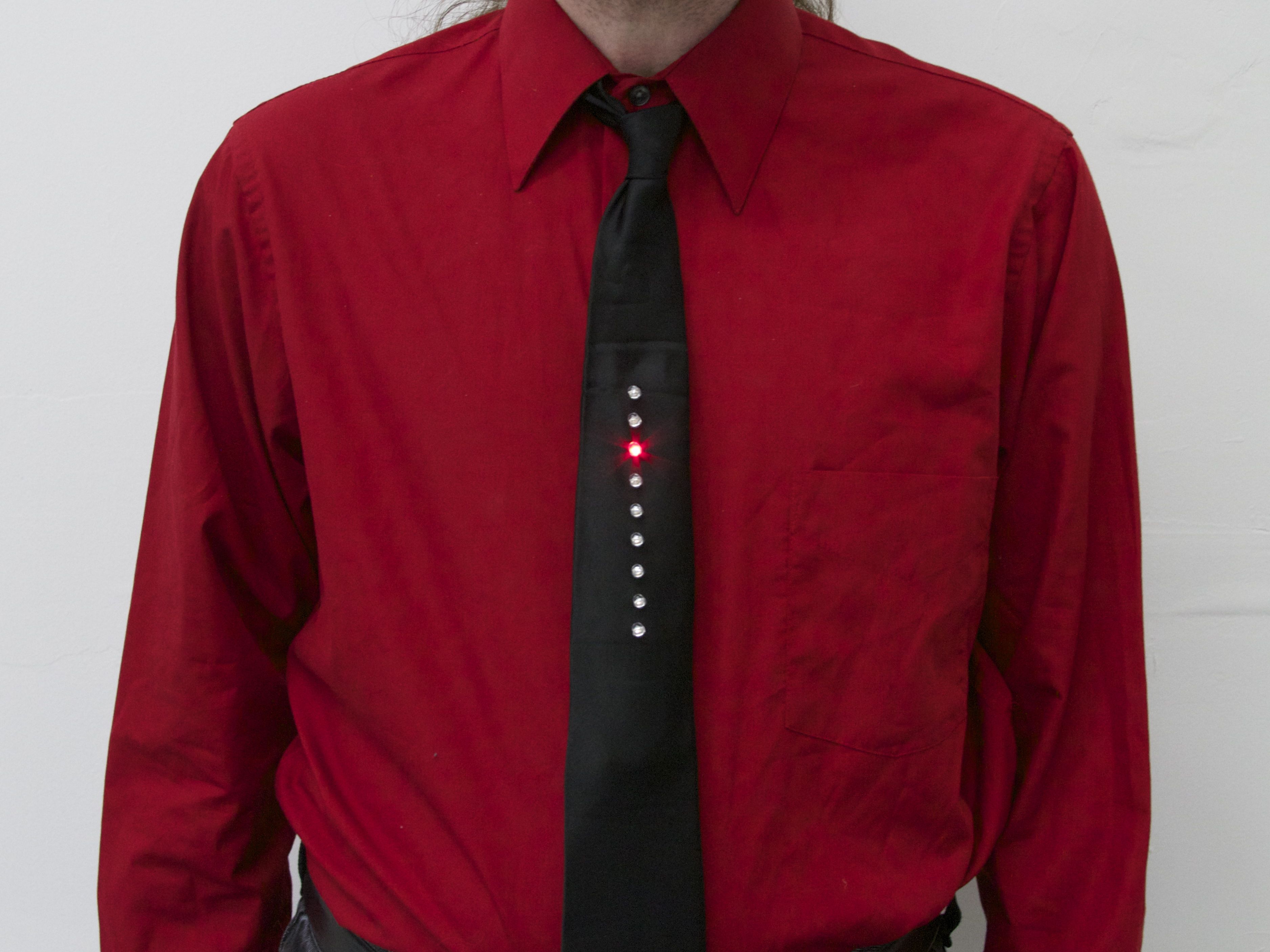
In the old videos of electronic music pioneers Kraftwerk performing their classic The Robots, a prominent prop is the animated LED necktie worn by each member of the band. If you haven’t seen this, or it’s been a while, you can see it right here at YouTube. (Additional viewing, if you’re so inclined: Die Roboter, the German version.)
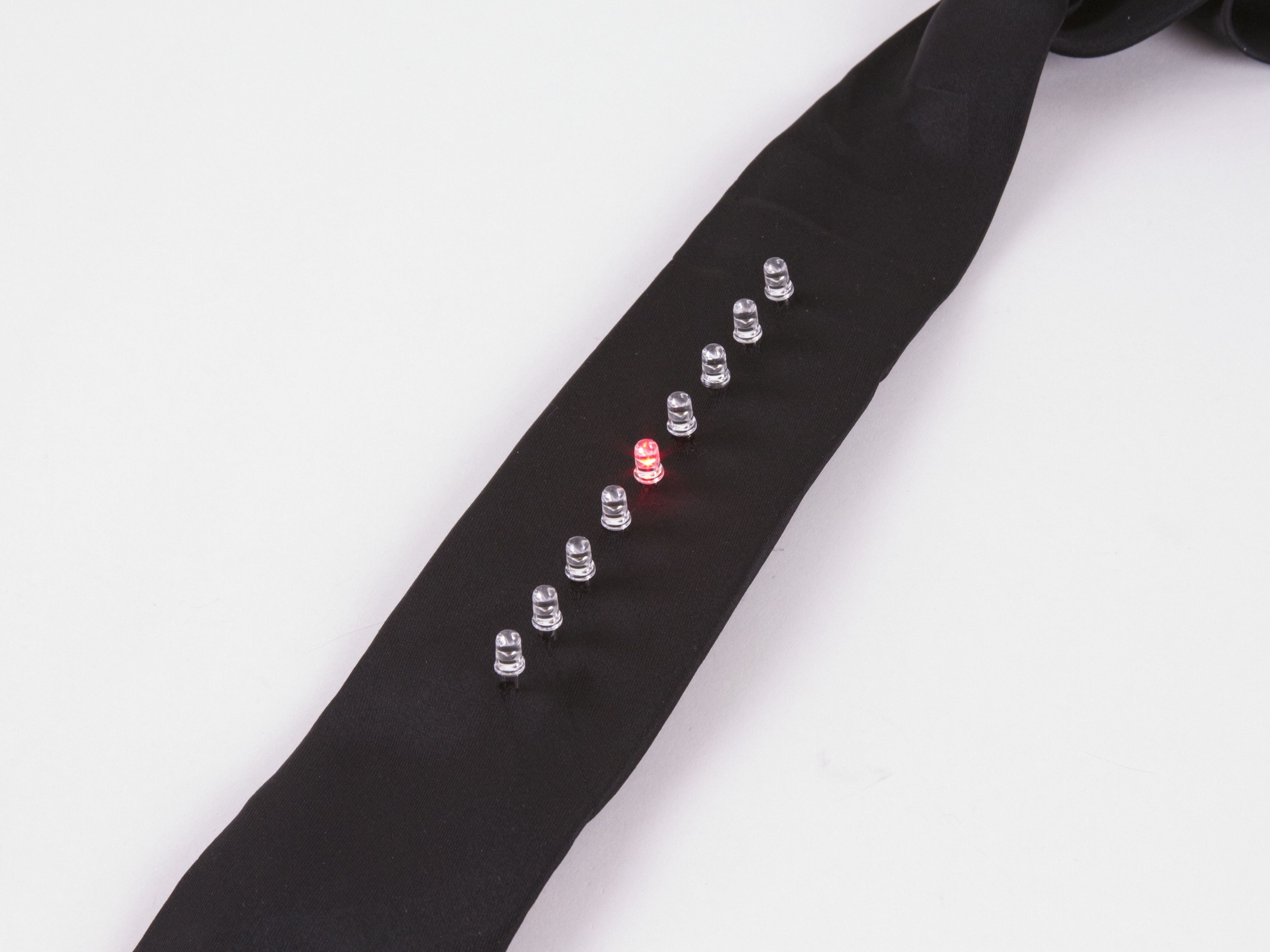
The Kraftwerk tie has nine red LEDs in a vertical row, and one lights up after the one above it in a simple descending pattern. And what does it say to the world? One thing only, loud and clear: “We are the robots.” Now, if you’re anything like us, the most important question going through your head at this point is something along the lines of “why am I not wearing a tie like that right now?”
The good news is that it’s actually easy to make one. And the starting point? A circuit with nine red LEDs and just the right spacing: our open-source Larson Scanner kit. With minor modifications– a software change and dumping the heavy 2xAA battery pack–it makes a pretty awesome tie. In what follows, we’ll show you how to build your own, complete with video.
Parts and tools needed
Here are the tools that you’ll need:
1. Scissors
2. Soldering iron (and solder)
3. Small angle clippers, for soldering
4. Wire strippers
Here are the parts that you’ll need:
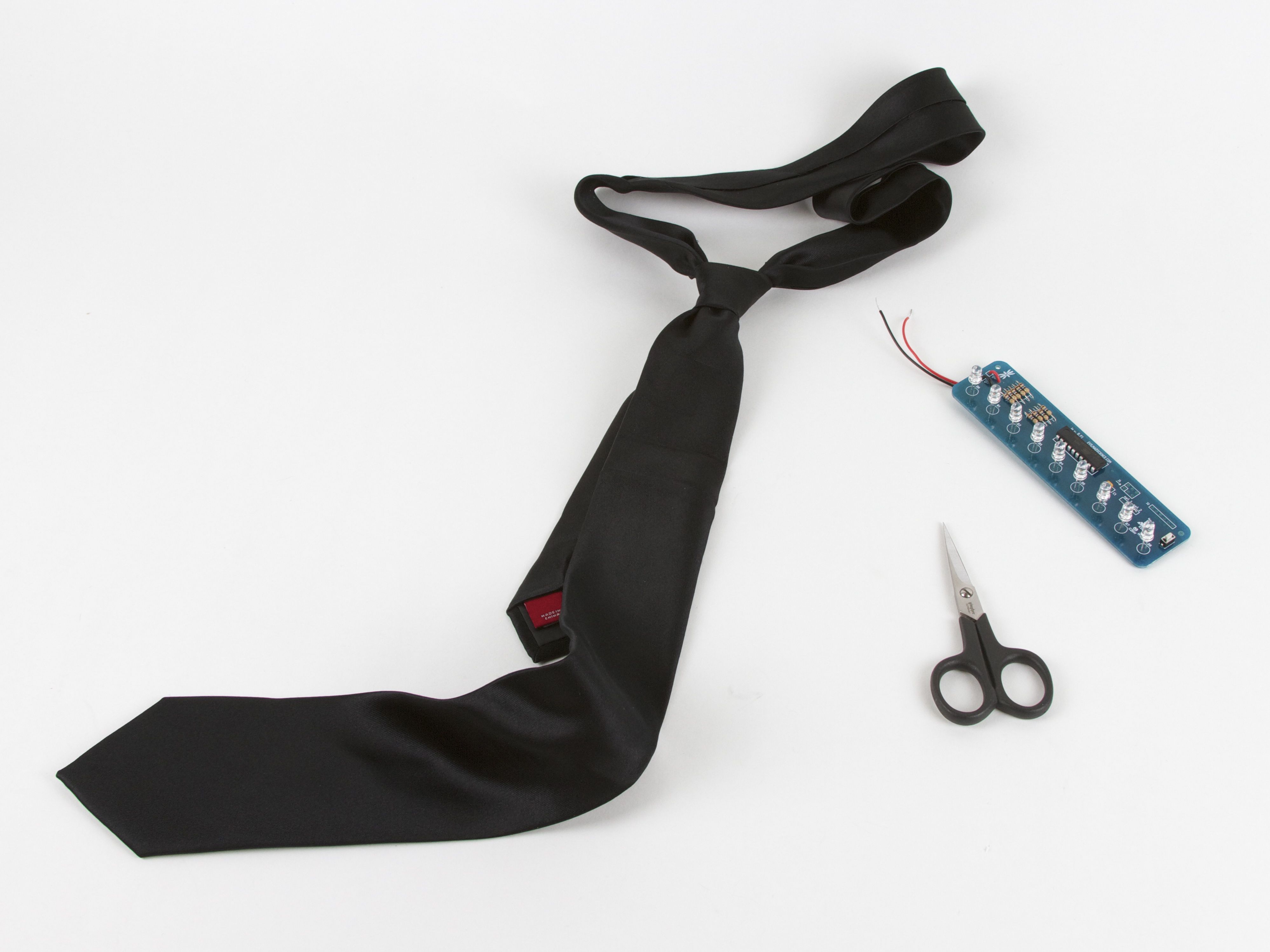
1. A necktie, preferably black.
2. CR2032 coin cell
3. Small binder clip
4. A few safety pins
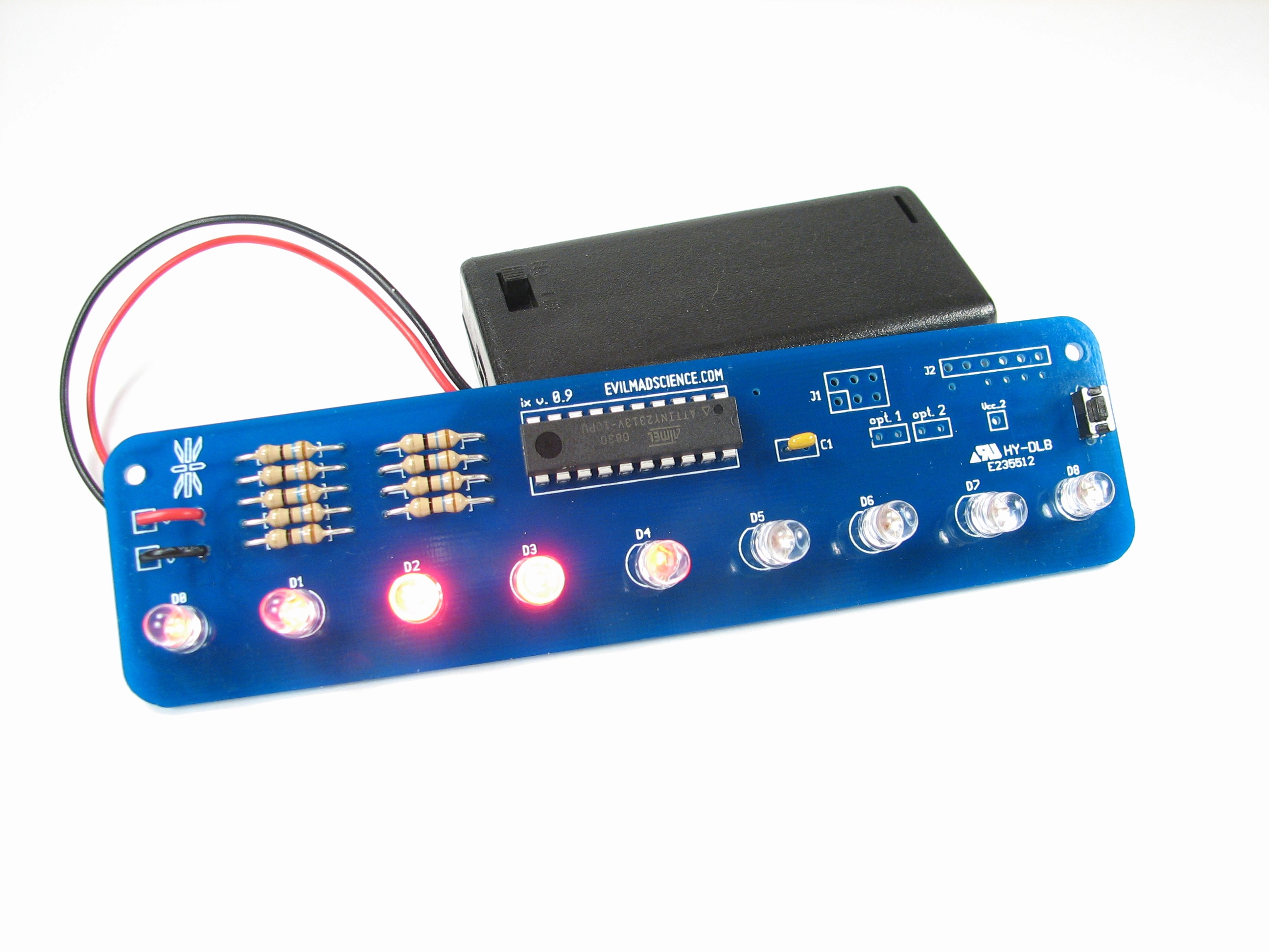
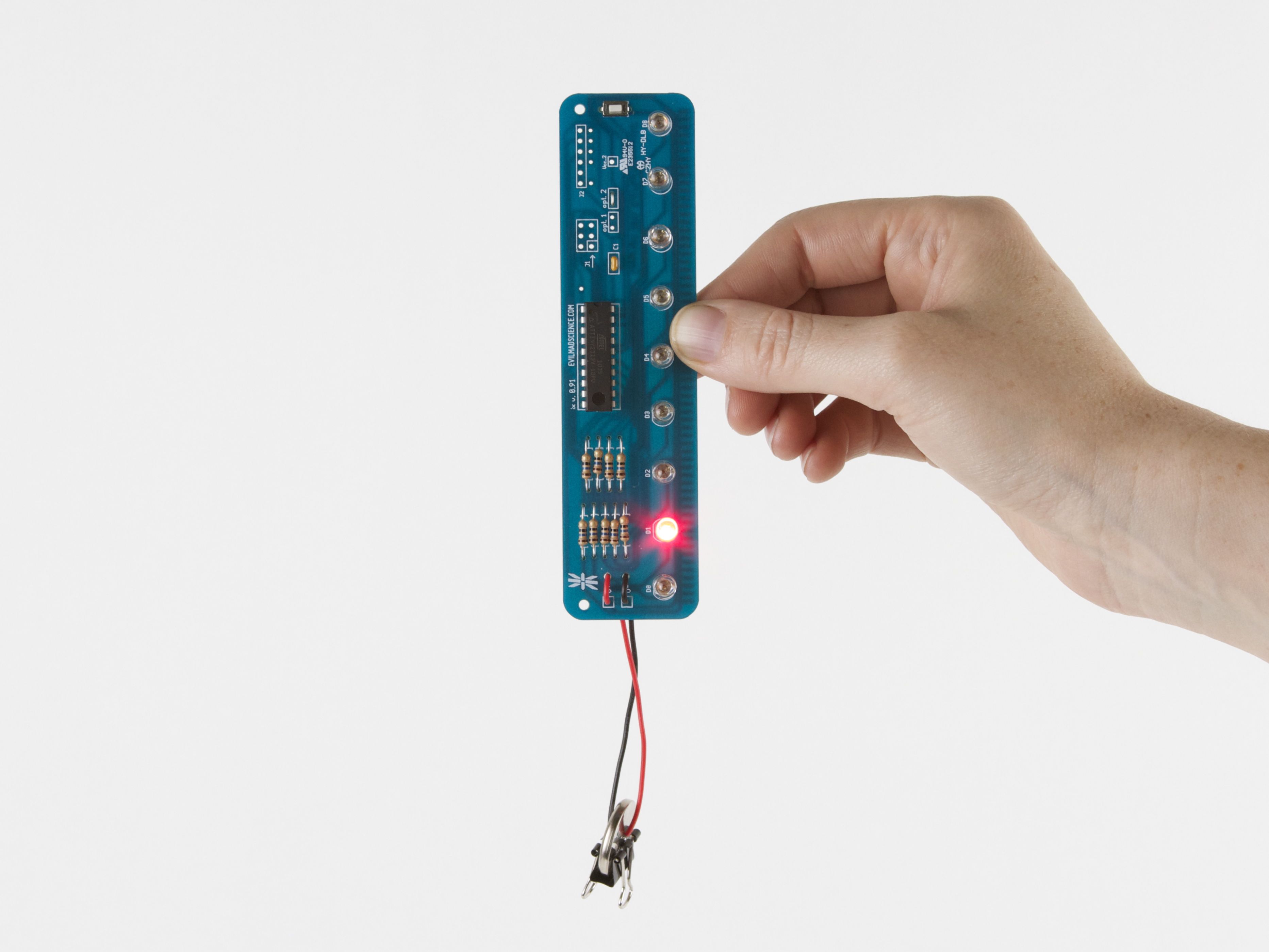
5. Larson scanner kit, with 5 mm red LEDs and firmware version 1.4 or newer
Firmware
The principal difference between “traditional” Larson Scanner behavior and the Kraftwerk-inspired LED tie is just in the software.
In a Larson Scanner, the LEDs gracefully scan back and forth, whereas our “robot tie” has the LEDs just step in one direction, without the gentle fades.
As of today, Larson Scanner kits from our store are shipping pre-programmed with firmware version 1.4, where firmware version 1.4 has the new “robot tie” animation mode built-in, as a configurable option. (So if you’re getting a new kit, no programming is needed. And, if you have an older Larson Scanner kit, you will need to upgrade its firmware, using an AVR ISP programmer. You can find the source code at the Evil Mad Science Wiki.)
Build video and demo
Before we get to the details of assembly, you might want to watch our video demo, that shows off what the circuits do, and walks carefully through the steps of actually inserting the LED board into the necktie. The video is embedded below. If you can’t see it here, click through to view it on YouTube.
Building the project
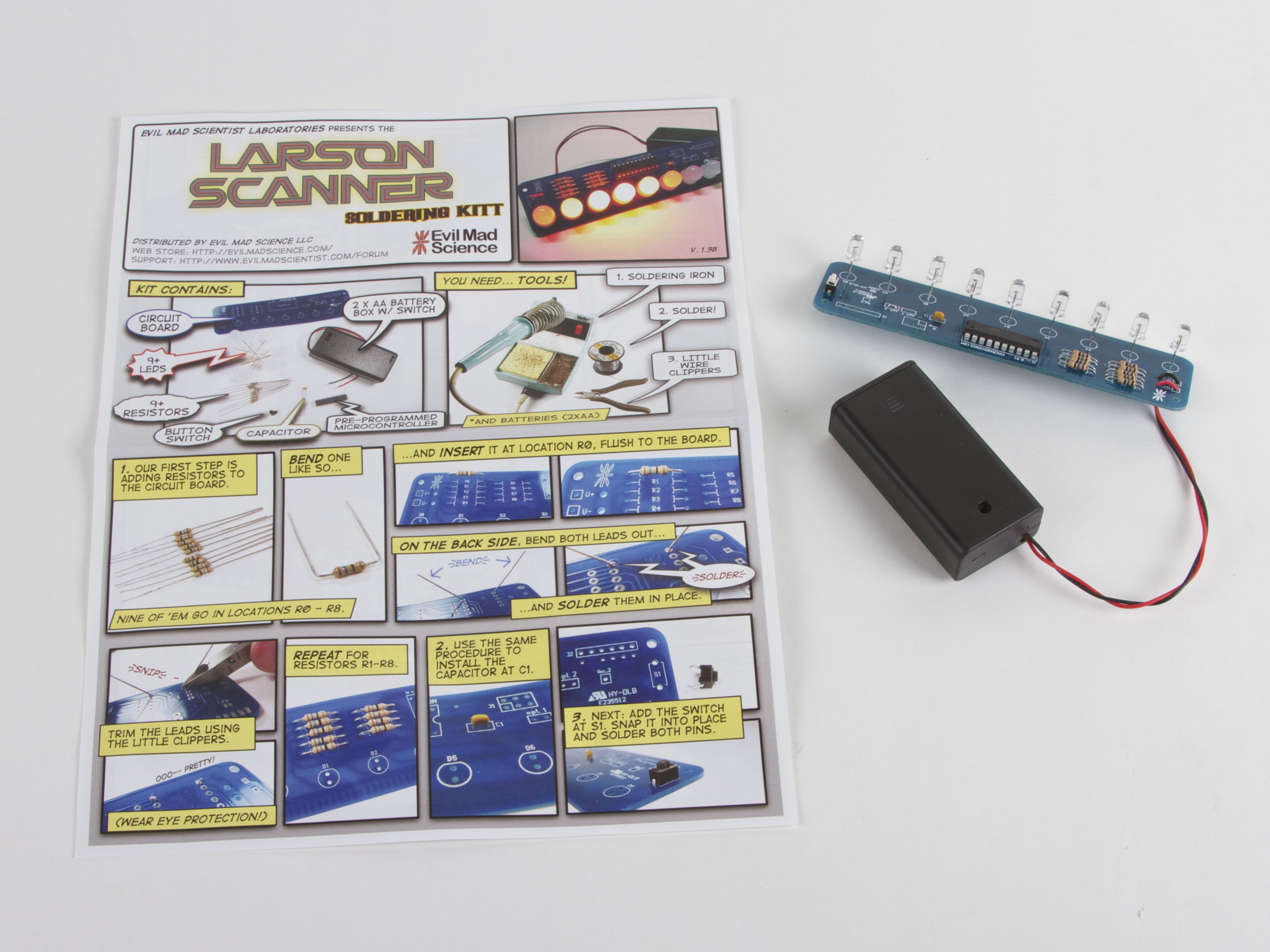
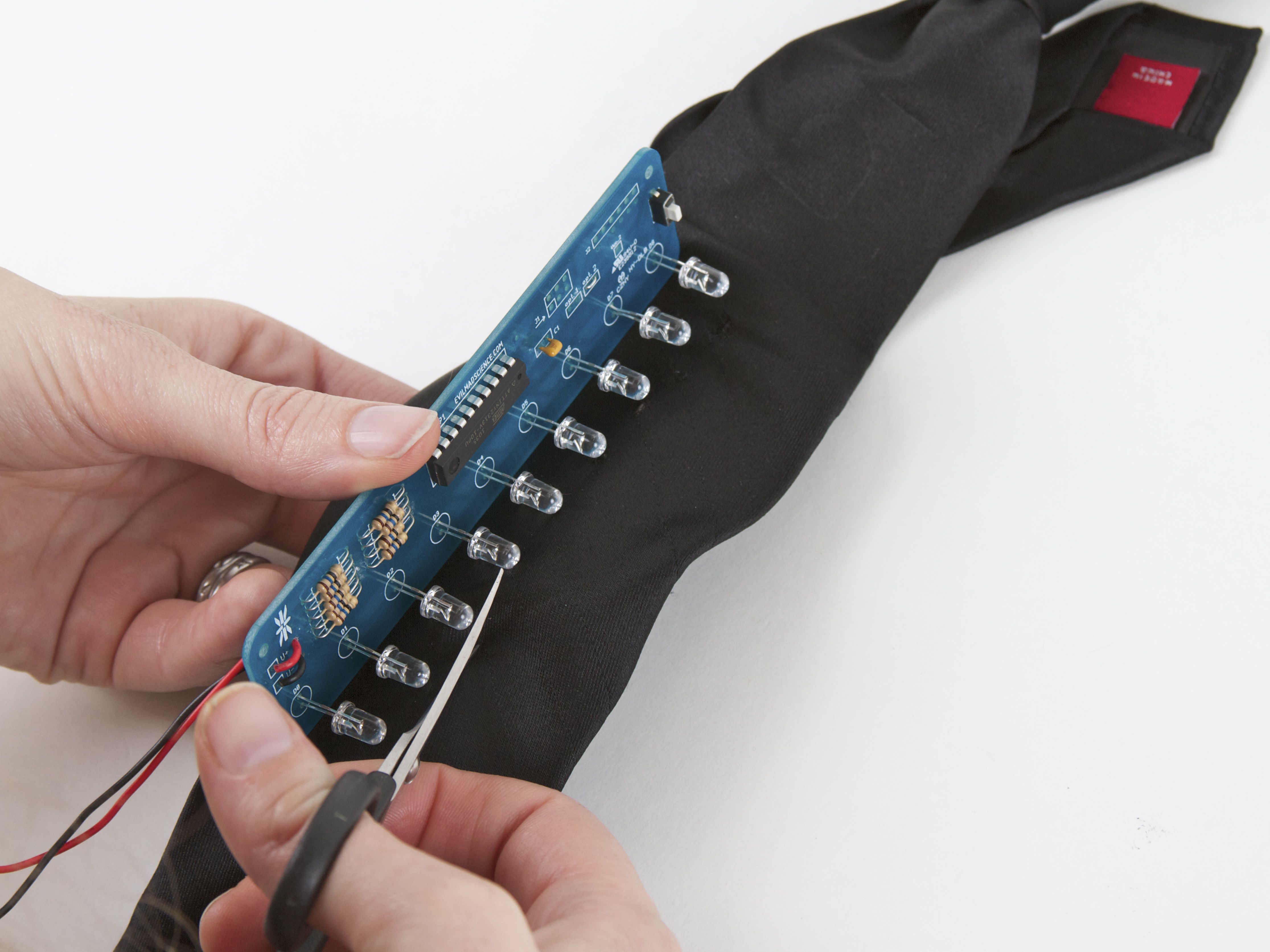
The first assembly step is to solder together the Larson Scanner kit, following the directions, with one possible change:
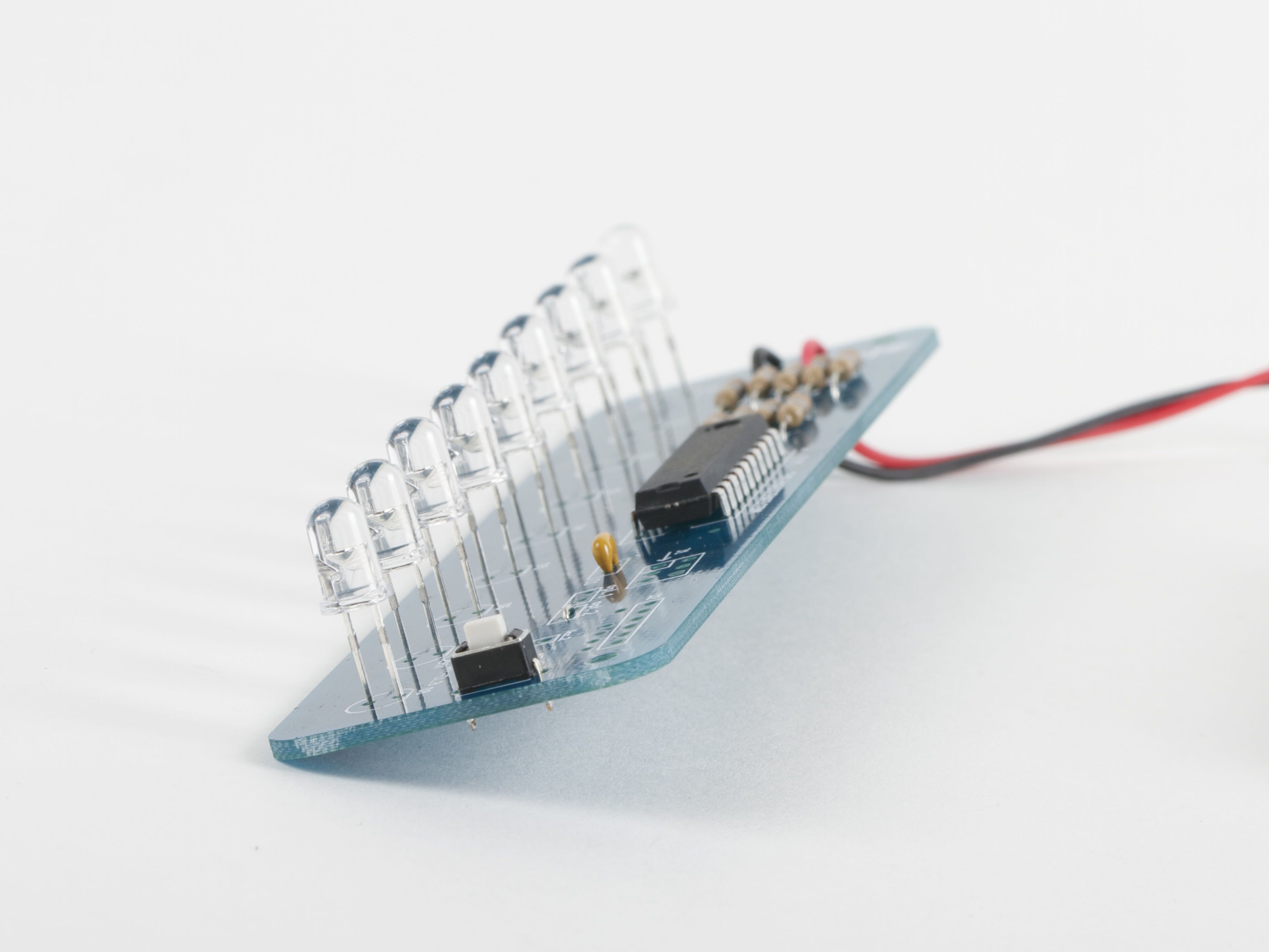
It may be helpful to space the LEDs above the circuit board by 1/4 inch (6 mm) or so, so that they’re easier to stick through the tie surface. A good way to do this is to cut a 1/4″ wide strip of heavy cardstock and thread that between the “legs” of each LED before soldering them in place. After soldering, pull the strip of cardstock out. (And, be careful not to set that cardstock on fire!)
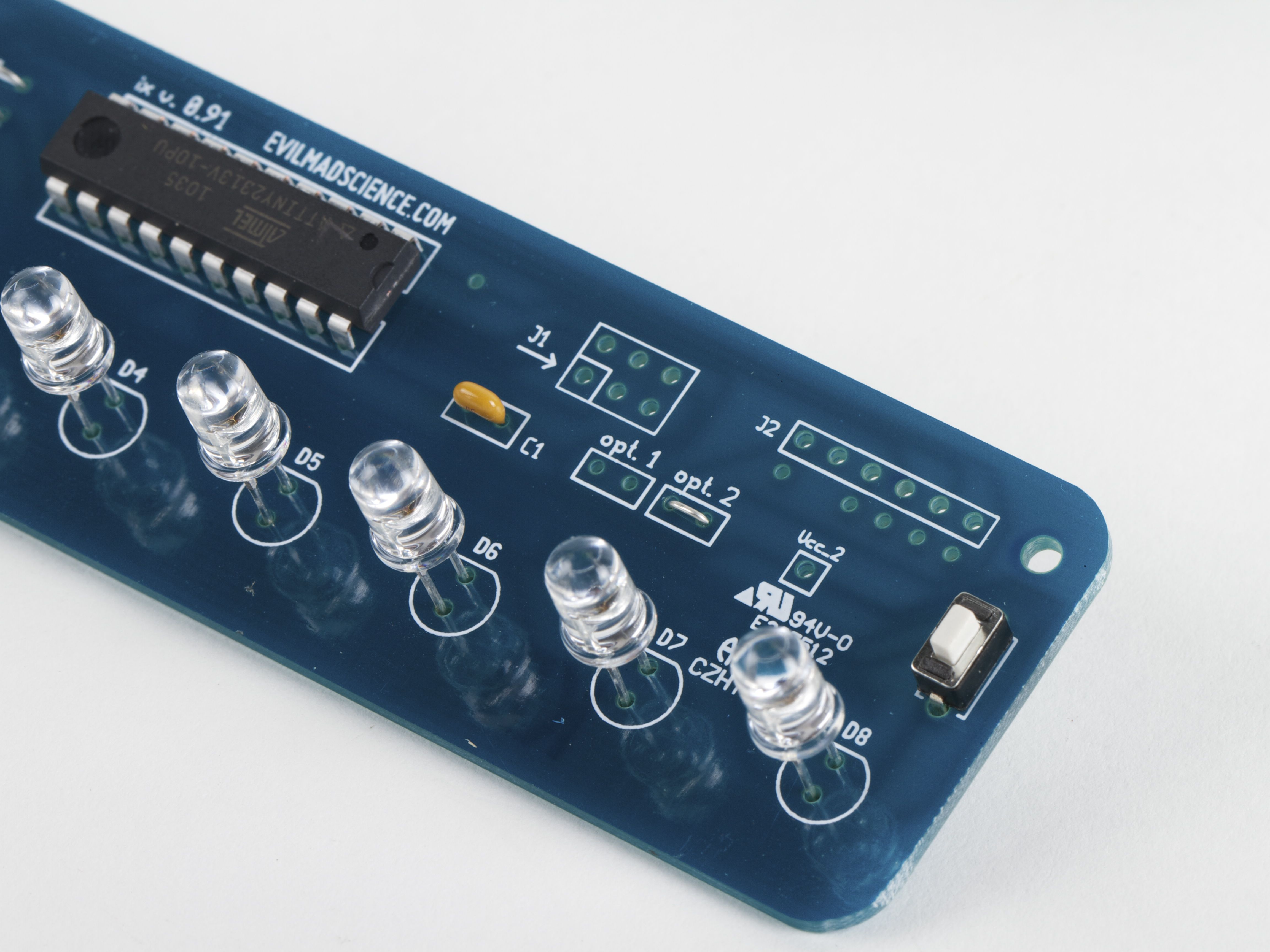
Next, solder a wire jumper– that is, a wire like a clipped resistor lead –between the two holes of location “opt. 2” on the circuit board. This wire jumper is the configuration option that switches it from Larson Scanner mode into “robot tie” mode.
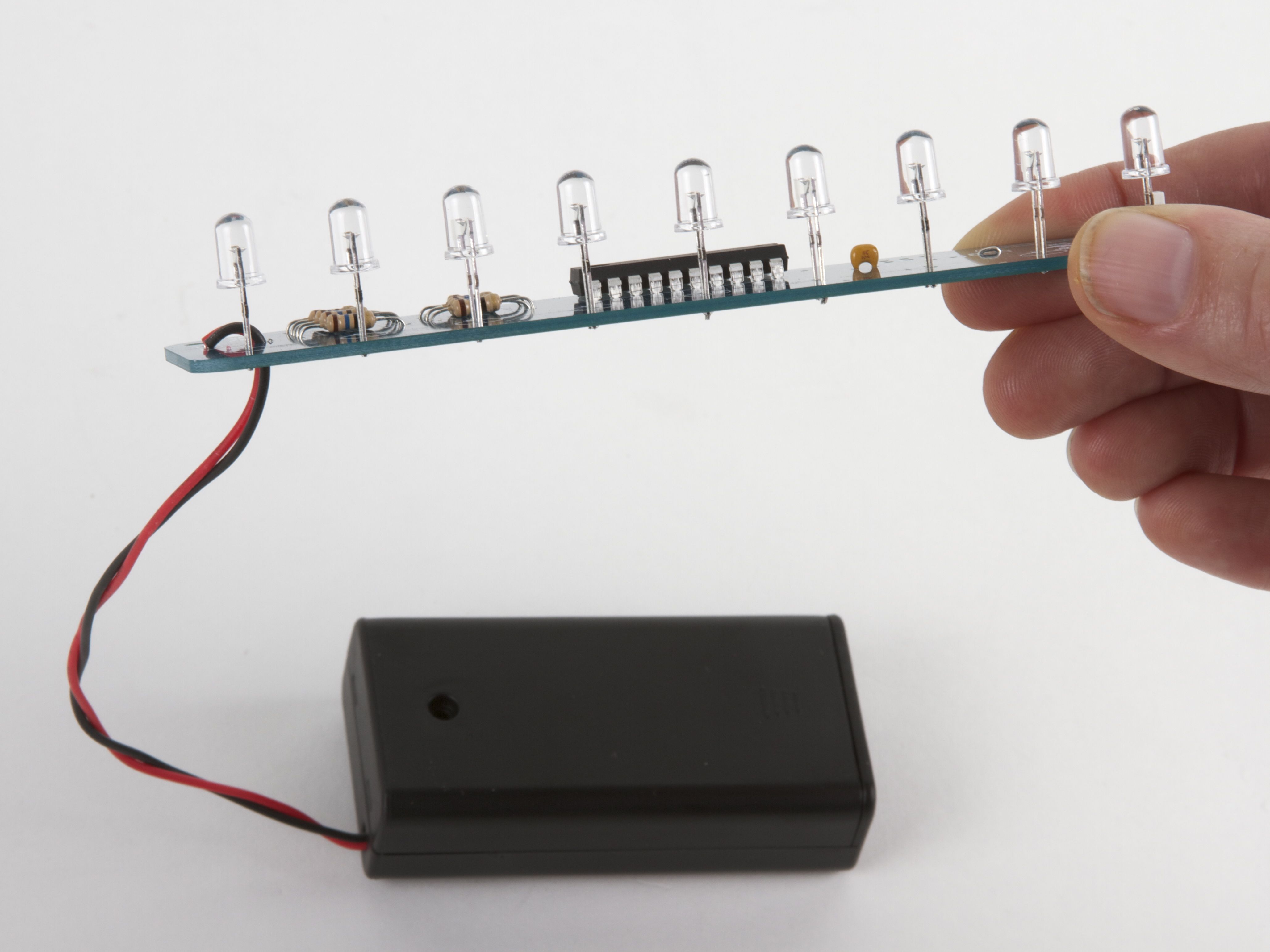
The kit is ready to useat this point, and will make a fine addition to your tie with one exception: that heavy 2xAA battery holder, which just doesn’t fit well on a tie. You can, of course, add longer wires and hide the battery holder in your pocket, but we actually have a better solution.
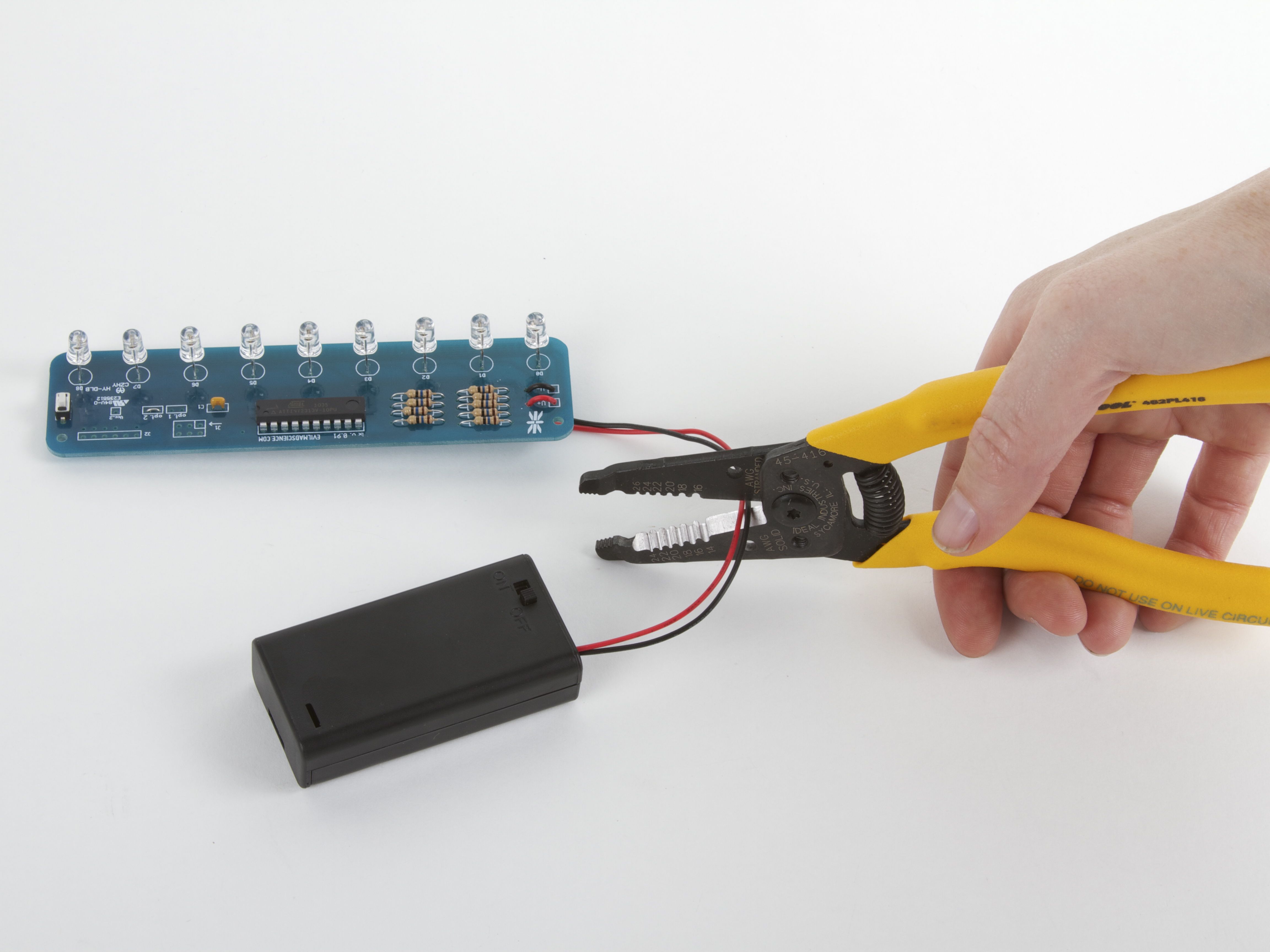
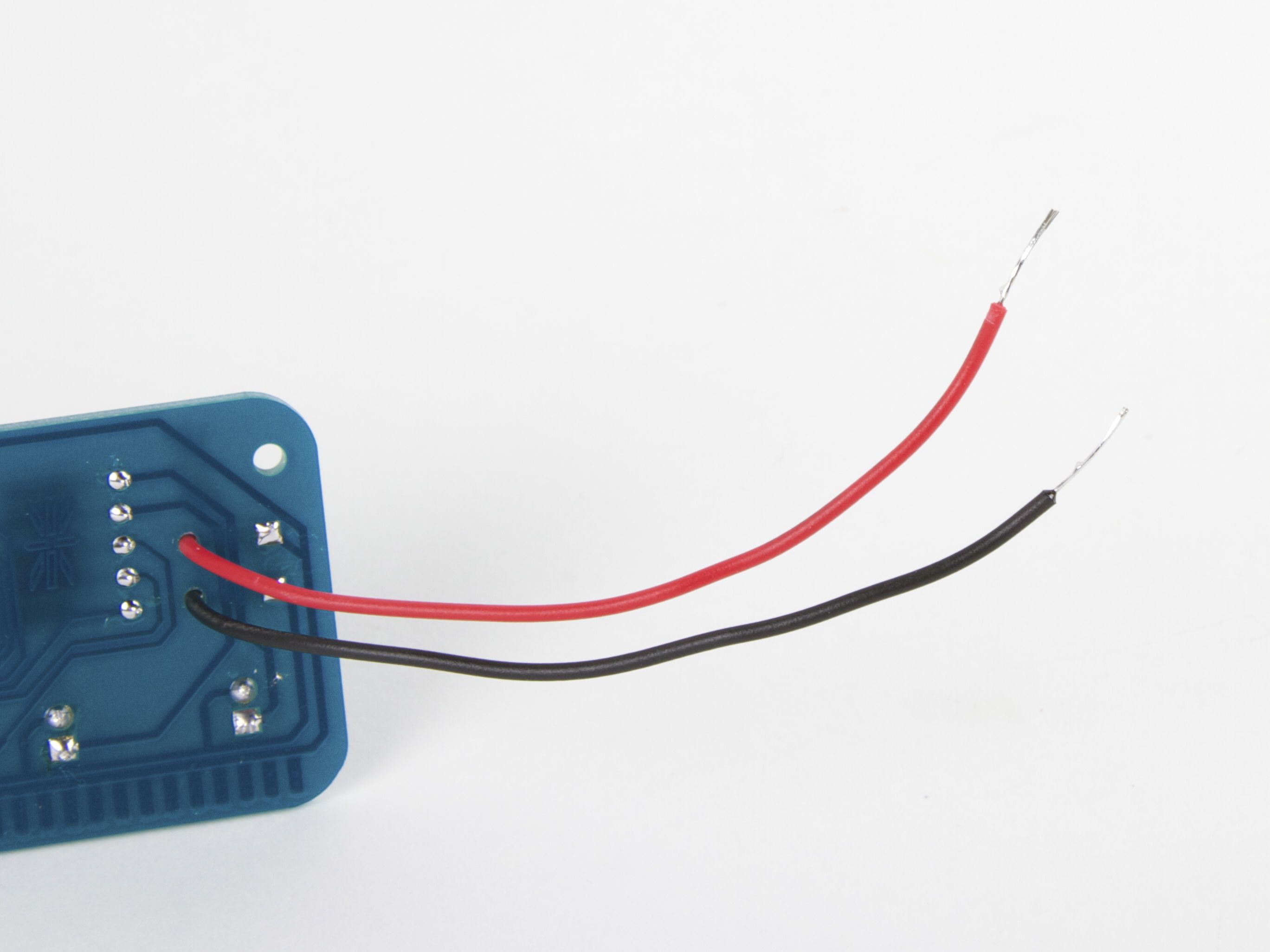
With the batteries removed from the holder, cut the wires to the holder, about halfway. Strip and tin (solder-coat) the wire leads, leaving about 1/4″ – 1/2″ exposed.
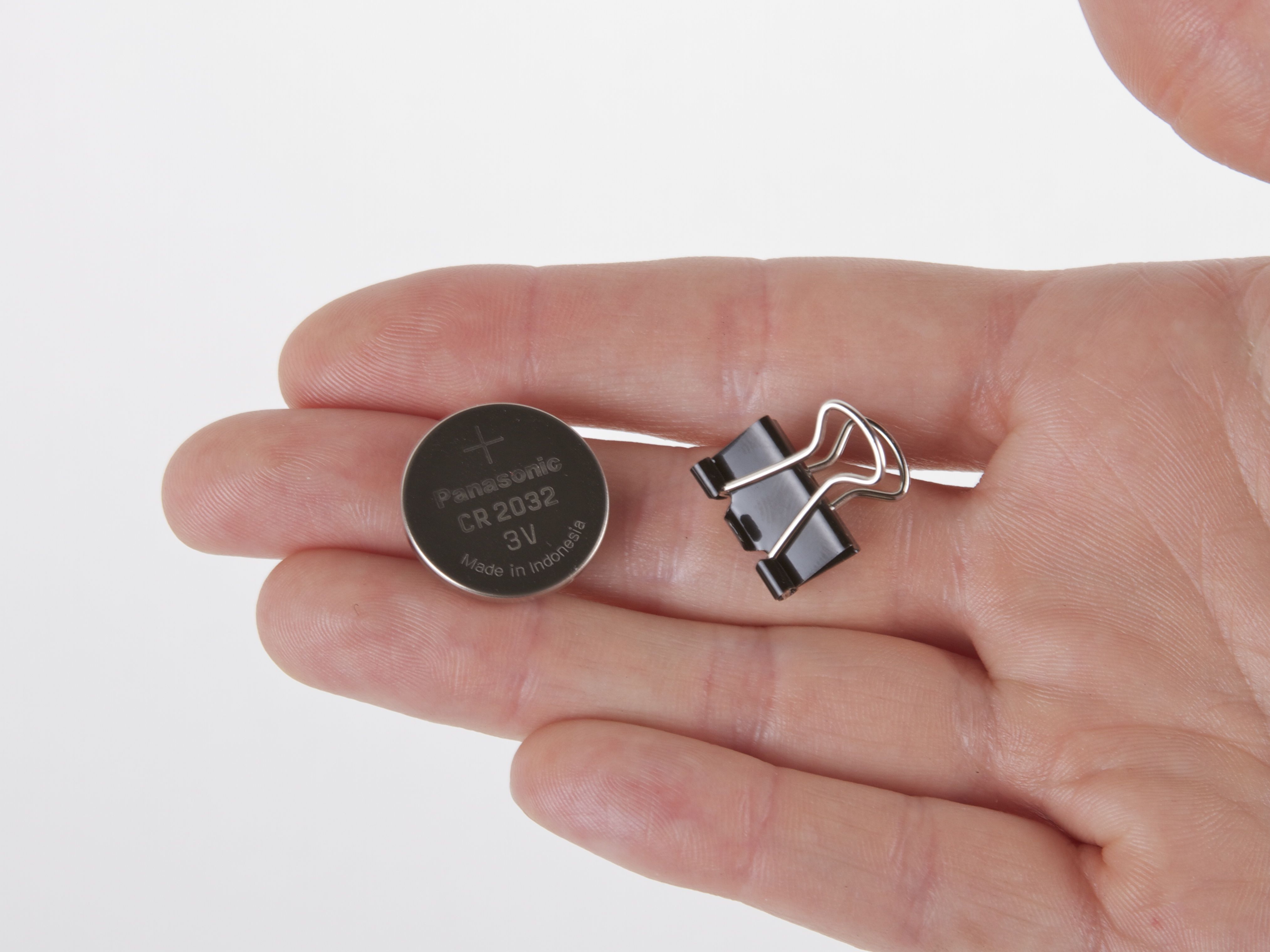
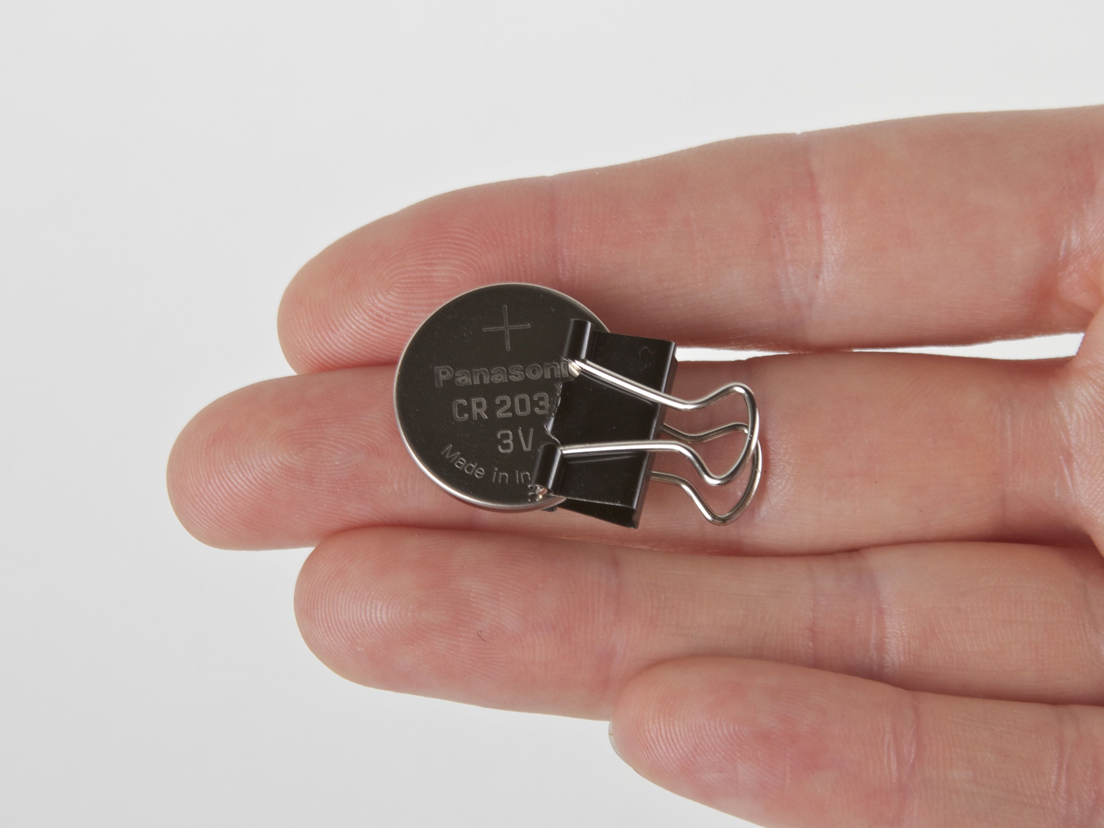
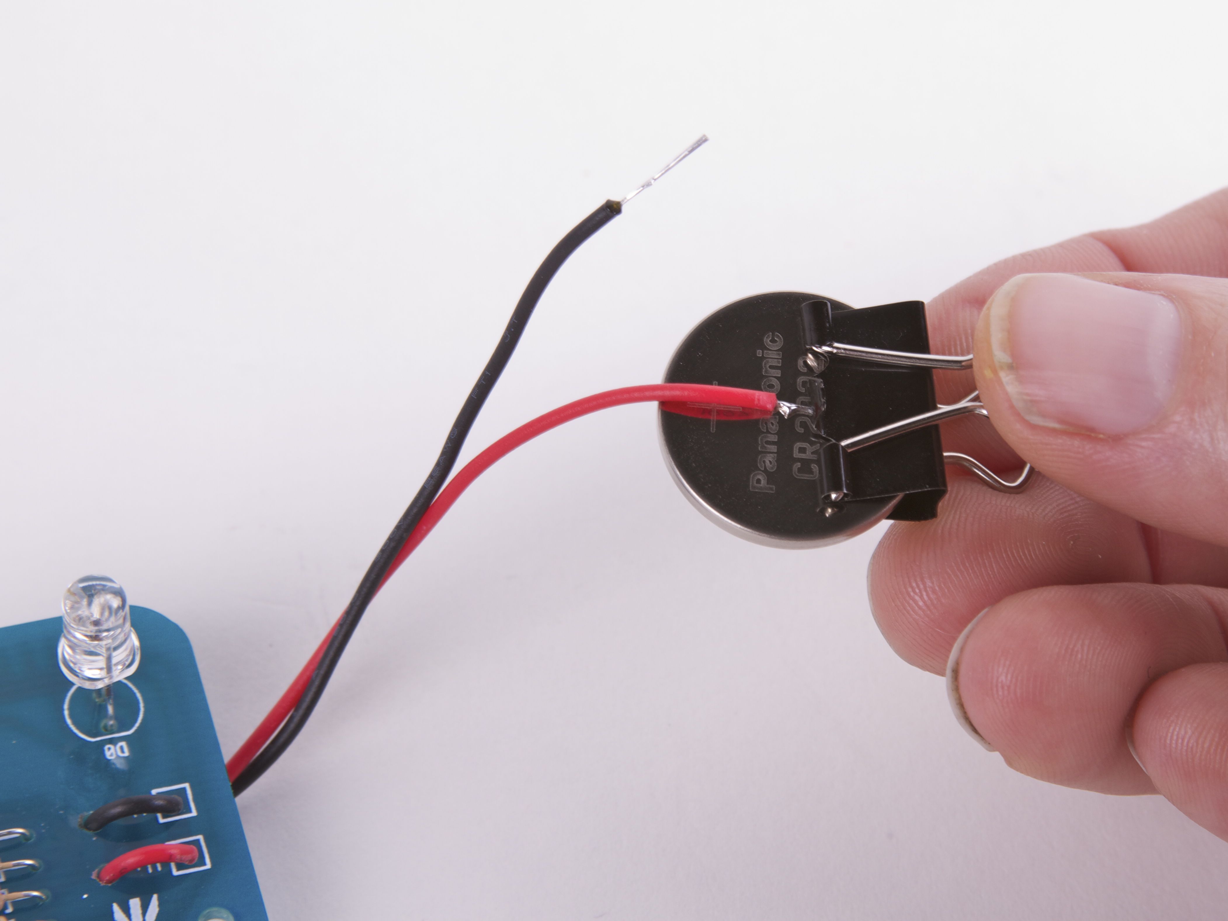
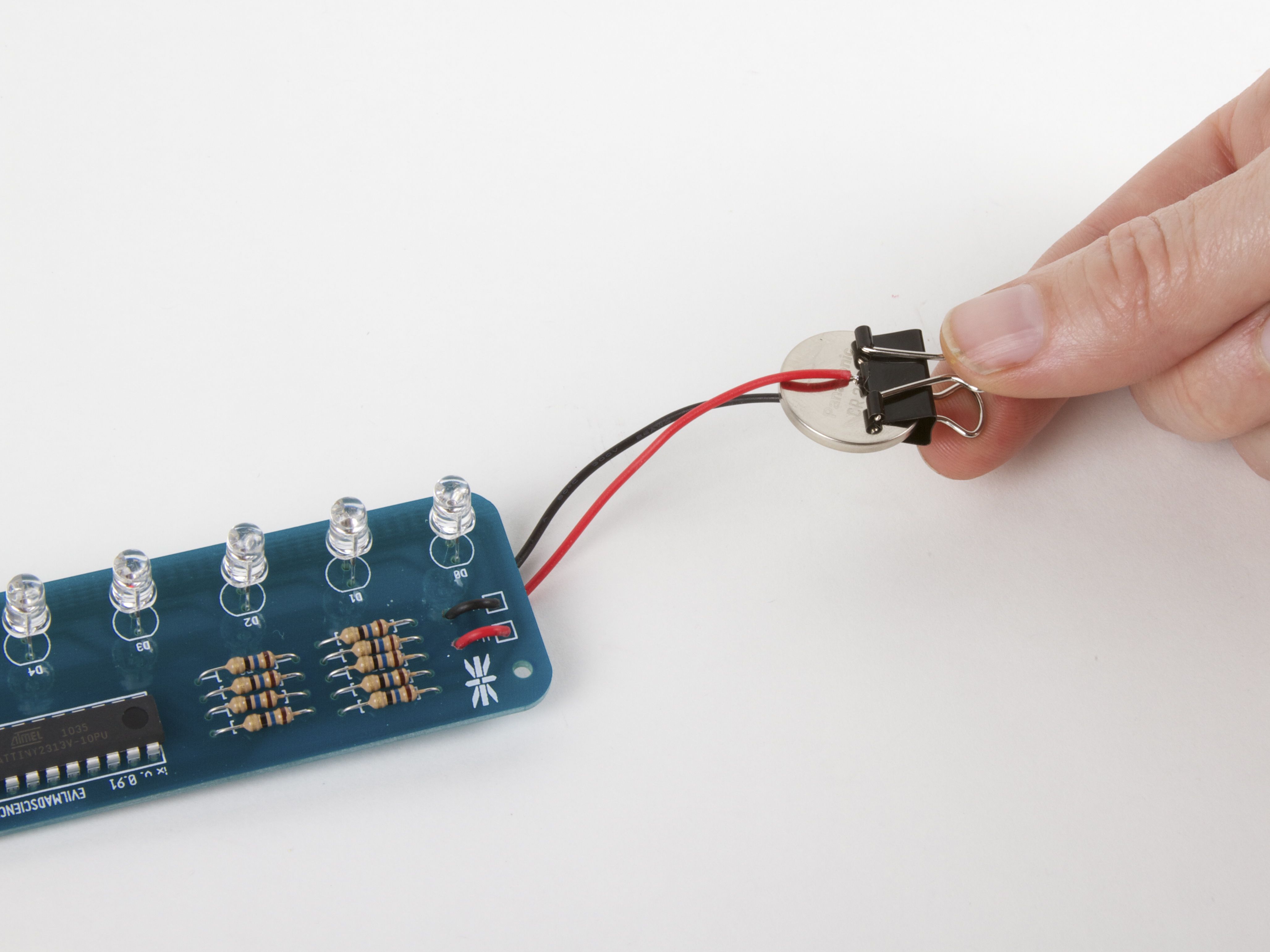
Next, we use a neat trick: A small binder clip makes a nice coin cell holder! If your binder clip is shiny or silver colored, you probably need to add a layer of tape (masking or packing tape) on the inside as an insulator. If you have a classic black binder clip like we do here, the black enamel actually acts as a good insulator– you can just go ahead and stick the coin cell right into the binder clip. Connect the red wire to the + side, and the black wire to the –side.
Aside: “Run a big circuit board like that from a coin cell? Are you crazy?” No, we’re not crazy, just slightly mad. It turns out that the Larson Scanner in “robot tie” mode uses just under 2 mA of current when in normal brightness mode, and about 8 mA of current in what we like to call “Hey you– turn that thing down!” mode. You can hold the button for a few seconds to switch between brightness modes. These are very reasonable currents for a coin cell. In normal brightness mode, the battery should last for at least 75 hours.
And there we go: Incredibly light, convenient, and bright!

Next, let’s get that sucker in a tie. Figure out where it goes, and mark the position of the top LED. Hint: Look in the mirror while doing this. (These LEDs should have gone an inch higher or so, for better authenticity.)
Hint #2: Don’t untie the tie at this point. From experience, it will be much harder to tie the tie again once it’s got a circuit board inside.

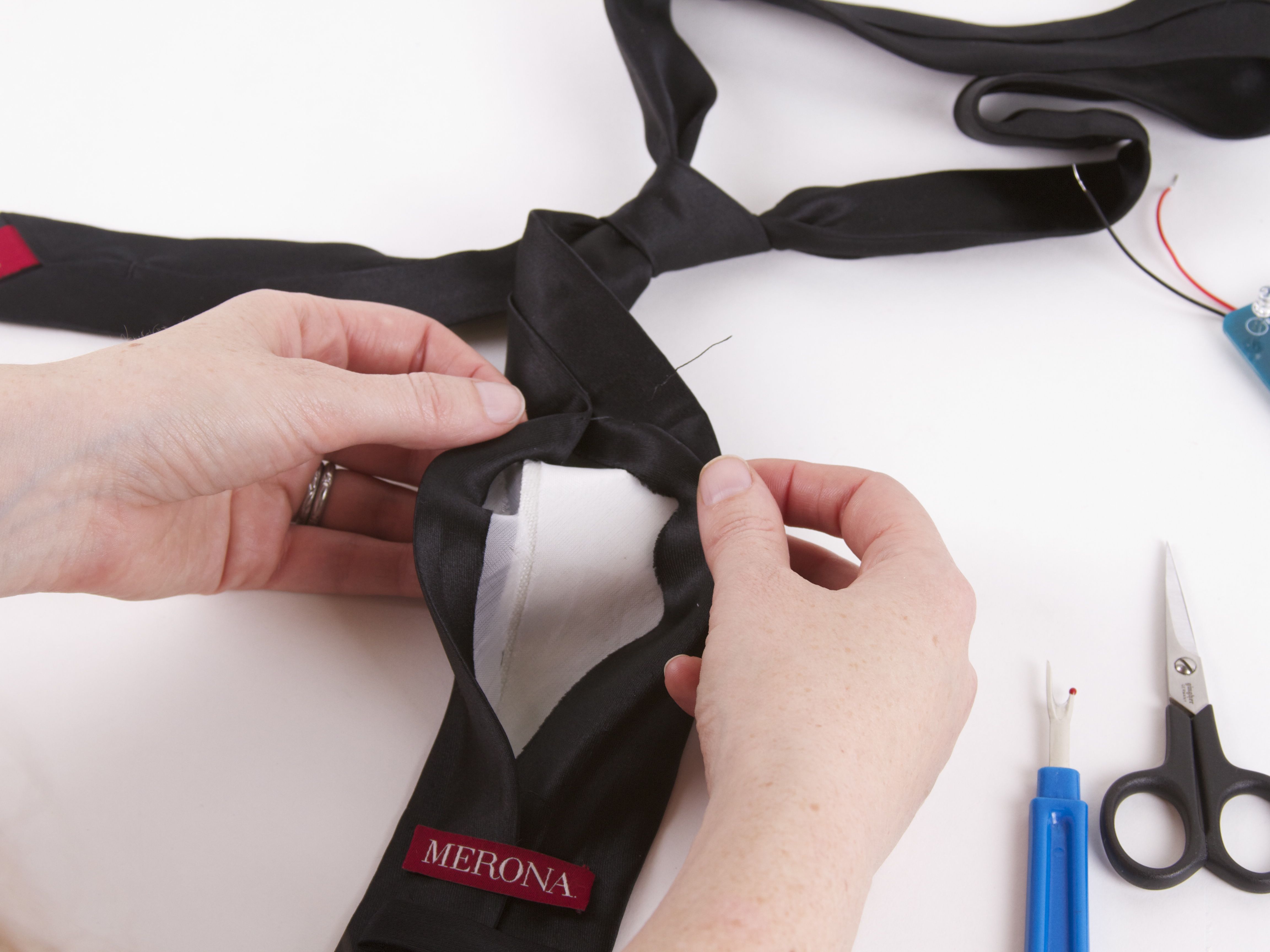
The front-facing part of the tie is a wrapped around piece of fabric, with a long vertical sewn seam on the back side. Using scissors or a seam ripper, cut through part of the seam, so that you can get inside. The tie may have one or more layers of stiffener fabric inside. We’re going to put the modified Larson Scanner right inside, and cut holes in the front surface that the LEDs can stick through.
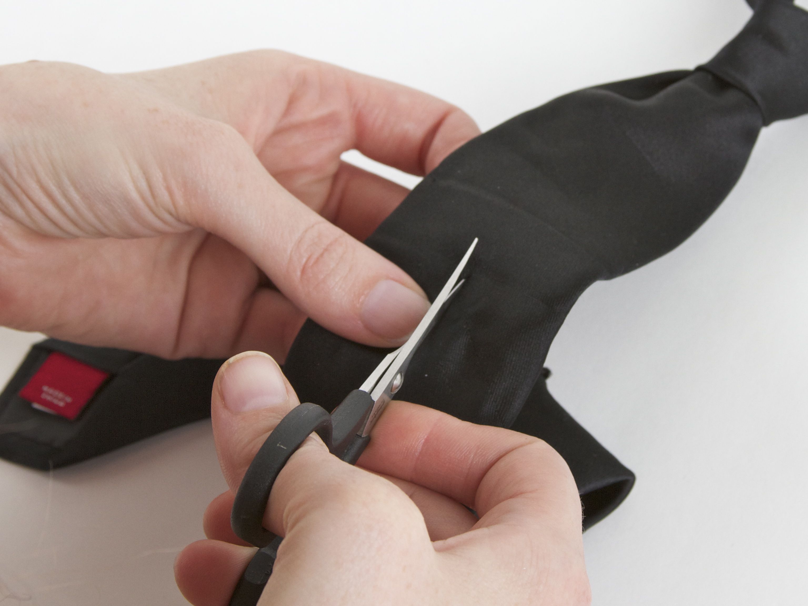
For each LED hole, cut only a tiny slit with the scissors– the LED can “pop” through, leaving none of the background circuit board visible. After the first hole, use the actual LED spacing as a guide for where to but the remaining holes.
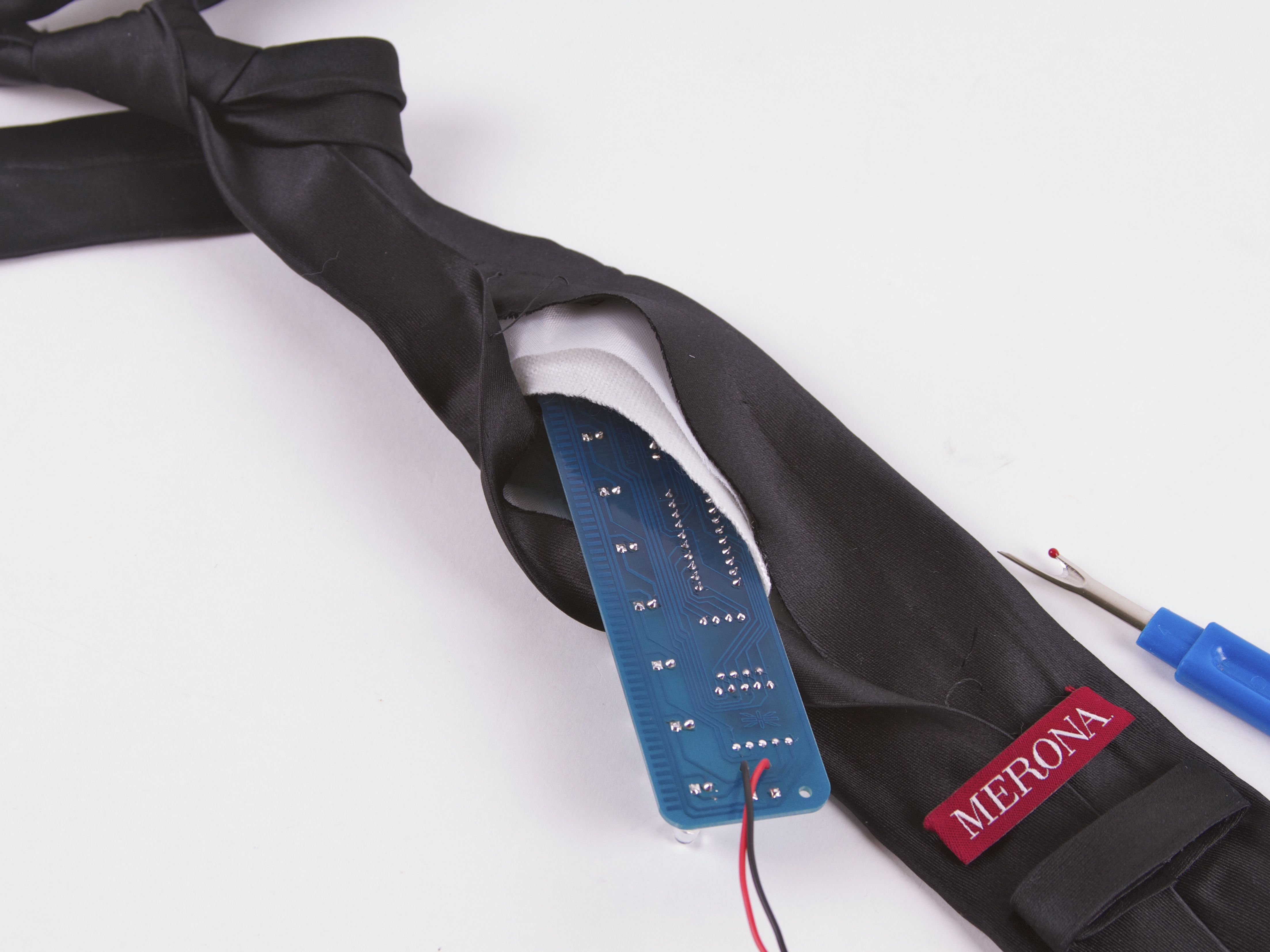
Insert the modified Larson Scanner, pop the LEDs through, and use a couple of safety pins to close up the back of the tie, where you cut the seam.
Ready to wear!
It’s worth mentioning that this isn’t remotely the only way to build Kraftwerk-inspired LED tie, nor the first– it’s just a convenient and practical method, starting with an easy kit. Notably, our friend Matt Sarnoff built his own tie some time ago, using a 555 and 4017 circuit. That circuit is almost identical to our first Cylon Jack O-Lantern, and is probably very similar to the circuit that Kraftwerk originally used. Versus that circuit design, our has typically much lower power consumption– making it easy to run on just a coin cell. And that’s not a bad thing for a wearable. :)
The Larson Scanner kit– complete with the new firmware –is shipping now at Evil Mad Science.
Source code and other documentation about the Larson Scanner is available
at the Evil Mad Science Wiki.
You can find more costume projects in our Halloween Project Archive.
When was the latest firmware released? I have a Larson scanner kit and built it into a shirt! So I guess I’ll be using a bistable witch of some sort instead of soldering a wire to change the program.
Yesterday, August 31, 2011. If yours predates that, it’ll need reprogramming to run this code.
Windell H. Oskay
drwho(at)evilmadscientist.com
http://www.evilmadscientist.com/
Why does this circuit have 9 separate current limiting resistors for the LEDs, instead of tying the cathodes together and having a single resistor to ground?
To permit patterns that light more than one LED at a time…
The resistor-per-LED layout allows you to light more than one LED at the same time.
A scan looks choppy when you turn LED1 off the same moment you turn LED2 on. It looks better when you turn LED2 on, wait for a moment, then turn LED1 off.
The EMSL firmware goes one better by lighting four LEDs at different levels of brightness: If LED5 is on (and LED6 is next), LED3 and LED6 are dim, LED4 is medium bright, and LED5 is at full brightness. That creates a smooth-looking scan with leading and trailing edges.
Thanks, I’ve always wondered that.
I just finished my version of this tie, and am extremely happy with the results. I’m sending it to my son to wear for Halloween at college; it should be a big hit. I was surprised and pleased with how easy it was to assemble, even though I haven’t picked up a soldering iron since high school!
I did make one modification: I took apart a little battery-powered LED tealight and used the housing to hold the battery, rather than use a binder clip. This way the leads would be protected from fraying, and it would be less likely for the battery to fall out.
Here’s a link to my project:
http://thereshesews.blogspot.com/2011/10/something-to-go-with-ians-tron-bag.html
I just finished making this one. And it was really fun doing this. I have never soldered before but with some help from a friend and the easy peasy instructions I managed to do it in a couple of hours! And thank you very much for your excellent and fast service and delivery to Sweden!!!