


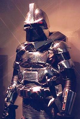
It’s a pumpkin! It’s a Jack-o-lantern! It’s an electronics project! It’s… a Cylon!
Cylons are great. They’re evil, menacing, and shiny. They have glowing red lights, computer-monotone voices, and they aim as precisely as imperial stormtroopers.
For halloween this year, we made Cylon Jack-o-lanterns in both large and small versions.
The design consists of two parts, a pumpkin-carving part and an electronics part. The big idea, of course, is to make the Cylon’s red eye scan back and forth.
How well does it work? Take a look! (Youtube)
This week’s Weekend Projects Podcast at Make Magazine is about making a programmable LED pumkin.
Our Cylon is made with a very different approach. It runs on a 9V battery and uses two cheap integrated circuits (a 555 and 4017) that together control six LEDs (or six groups of LEDs).
Circuits like this are quick, easy, and cheap to build. It’s also fun merely from the standpoint of making something that people might expect to require a microcontroller. For this particular circuit, it turns out to be cheaper and faster to do it without one.
If you’re handy with a soldering iron, you can build this circuit for less than ten dollars, in less than two hours, without any programming at all.


Let’s get started with the pumpkin. Here’s our first victim, a pie pumpkin roughly six inches across. The first step is to mark up the design. Some people like stencils, I like to draw on the pumpkin with a Sharpie, cleaning up later with rubbing alcohol. It works pretty well.

Digging around in the kitchen, I found a wide assortment of carving and garnishing tools. To these, I added my hobby knife, scissors, and precise tweezers. As it turned out, I ended up doing most of the carving with two tools: the hobby knife and the Microplane zester (not shown). All these other guys are nice, but they all seemed too clunky or specialized when it came down to it.

Here’s the completed carved pumpkin, ready for the eye to be inserted.
Electronics
The scanning eye of the Cylons is awfully similar to the one that KITT had on Knight Rider. It’s possible that KITT was built by Glen A. Larson using recycled Cylon technology.
As some people have pointed out, the scanner also similar to the eye of the robot Gort in The Day the Earth Stood Still. You can even watch the relevant clip from that movie on YouTube, but you might notice that it’s not quite the same.
Although the basic premise is the same, for some reason there are a lot more KITT circuits than Cylon circuits floating around on the net. (There are some Cylon circuits; Here is one that looks complicated!)
The starting point for our circuit is the “standard”
KITT scanner circuit. There are quite a few variations on the basic theme, and we’ll pick and choose the parts that we like.
This circuit is based around the CD4017 decimal counter chip. This is a chip that counts the cycles of a clock signal that is input to one of its pins. It counts from 0 to 9, sequentially turning on the outputs labeled #0 through #9 as it counts, and then it starts over. We will use outputs #0 through #5 to light up our six LEDs in order, and then use the output values #6 through #9 to light up the LEDs in the opposite order, like so:
| LED Number | Turned on by count value | 4017 output pins |
|---|---|---|
| 1: | #0 | 3 |
| 2: | #1 or #9 | 2 or 11 |
| 3: | #2 or #8 | 4 or 9 |
| 4: | #3 or #7 | 7 or 6 |
| 5: | #4 or #6 | 10 or 5 |
| 6: | #5 | 1 |
There are a number of ways to provide the clock signal. One nice way is to use a standard 555 timer chip.
Both the 4017 and the 555 are CMOS chips capable of operating with a 9 V power supply, so we’ll set things up (1) to use a convenient single 9 V battery and (2) to use a 555 timer chip.
555’s are almost as cool as Cylons. While I used the power-hungry NE555, you can also use the power-efficient version, the ICM7555. (See more
555 timer circuits here, here, here, and
here.)
We’ll build the circuit in a few separate blocks to keep things neat and orderly. All of the parts that we’re using are quite common; any decent electronics shop (i.e., not Radio Shack) should have everything that you need. (If you do have trouble locating parts, take a look at the list of “Suggested Parts” down below.)
Step 1: Let’s start by wiring up the 555:
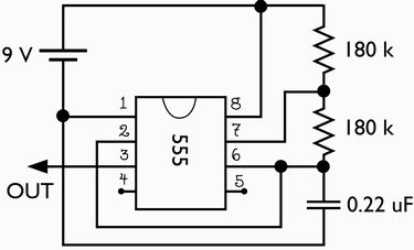
Solder the 9 V battery connector where the battery is shown, with the negative (black) wire to pin 1 and the positive (red) wire to pin 8. We’ll refer to these points later as “Ground” and “+9 V”, respectively. (Yes, picky people, it’s an effective ground, not an earth ground.)
Pin 8 is connected to pin 7 through a 180 kilo-ohm resistor, and pin 7 is connected to pin 6 through a second a 180 kilo-ohm resistor. The 0.22 uF capacitor connects pin 6 to pin 1.
Use a wire to connect pin 2 to pin 6. Pins 4 and 5 should be left unwired.
Pin 3 is our “clock” output, which we’ll be taking to the 4017 in the next part of the circuit.
Note added: It’s an excellent (but optional) idea to test the output of the 555 at this point, to make sure that the clock signal is really coming out. You can do that as follows: take the output from the 555 and connect it, through a 330 ohm resistor, to an LED and then to ground. If everything is correct so far, the LED should blink rapidly.
Step 2: Wire up the inputs to the 4017.

There are quite a few connections to the 4017 chip, so we’ll split them into two diagrams for ease of reading.
First, connect the clock output from the 555 to the clock input at pin 14.
Besides the clock input, there are four other inputs to the 4017. Wire pin 16 to the + 9 V, either at pin 8 of the 555 or directly to the red wire from the battery connector. The remaining three connections are to the ground, so wire pins 8, 13, and 15 to the black wire from the battery connector or to pin 1 of the 555.
Step 3: Building some easy “OR” gates.

Connect a diode, such as a 1N914 or a 1N4001, to each of the ten decimal output pins of the 4017 and wire the cathodes of those diodes as shown, forming six outputs that will drive the LEDs.
Pin 12 is left unused.
[If you want to know why we’re using the ten diodes, please see the aside at the end of the story.]
Step 4: Driving the LEDs
You can hook your six LEDs directly to the outputs shown above; just connect the LED between where it says “For LED X” and ground, with the cathode side towards ground.
Well, that’s the easy way. It works, and it looks good. But if you look closely, it’s a little too perfect.
The lights in the original Cylons were incandescent, not LEDs, and the effect is quite different.
LEDs turn on and turn off very quickly. The result is that the lights in our circuit seem to blink on and off, rather than smoothly transition from one light to the next. In order to slow down the transitions, we can also use a low-pass driver circuit to drive each LED. To do this you will need six 47 k resistors, six 47 microfarad capacitors, six 2N3904 transistors, and one 330 ohm resistor.

A low-pass LED driver consists of a low pass filter and a simple NPN transistor amplifier.
To build one, begin by connecting one the outputs from the previous step (“For LED X“) to a 47 kilo-ohm resistor. The other end of the resistor connects to the base of a the transistor. (Look here if you need help identifying the Emitter, Base, and Collector of your transistor.)
The base of the transistor also connects to a 47 microfarad capacitor. The other end of the capacitor is connected to the Emitter of the transistor (labeled with an “E” in the diagram) and to ground (the negative terminal of the battery). The capacitor is probably a polarized type, meaning that it must be hooked up with the side labeled “-” (or a big stripe) towards ground.
To hook up the LEDs, start by attaching a single 330 ohm resistor to the + 9V supply. The LED connects from the 330 ohm resistor to the unused pin of the transistor, the Collector. (You can hook all six of the LED anodes to the same 330 ohm resistor, so you will only need one of those.)

Here’s what the completed circuit looks like. It’s actually a tiny circuit without much going on– not nearly as bad as I’m sure that I’ve made it sound!
You can see the battery on the snap connector, the 555 and 4017 chips, the six transistors, six capacitors, and six resistors of the output drivers, and six large LEDs. I used six giant (10 mm) orange LEDs that I got at the local shop for $0.40 each. I thought that the orange would complement the pumpkins nicely. In retrospect, it might have been better to use red ones.
Here is a close-up of the board, if you want a better look.
I made a little movie of the circuit operating in the dark, so that you can see the action of the low-pass filters, it’s pretty nifty. Take a look. (176 kB Quicktime .mov file)

Put the circuit in a plastic bag to prevent damage due to moisture inside the pumpkin.

It’s a Working Cylon! It looked awfully small, and not nearly imposing enough, so I propped it up on this toaster. (That helped.)

We also made an extra-large Cylon. Carving this one was much easier; these big pumpkins are just made for carving. The changes to the circuit are minimal. (1) The 330 ohm resistor was removed (shorted across), and (2) In place of each single LED, there are now four super-bright LEDs in series, for a grand total of 24 LEDs in the circuit. These are really bright.


Here’s the giant Cylon in his lit-up glory. If you really want to go for that 70’s look, you need to use a star filter, as in the photo on the right.
Repeat after me: “BY YOUR COMMAND!”
I made a little movie of this one operating, so you can see how it looks; it’s totally worth the effort to build one of these!
Take a look. (236 kB Quicktime .mov file, the same one that’s linked in the introduction.)
Have fun and Happy halloween!
Suggested Parts
Here is a partial list of parts you’ll need, which might give you a head start if you’re not used to shopping for electronic components. There are suggested part numbers from BG Micro where appropriate. You can get equivalent parts from other sources as well, for example Digi-Key. BG Micro does not sell individual resistors– they sell packs of 100 for $3. If you have neither a stash of resistors nor a local electronics shop that can sell you these, I suggest getting resistor assortment RES1363 from BG Micro for $10.95, which includes 10 each of 61 different resistance values. Approximate values for the resistors and capacitors are fine, but be sure to use matched (nominal) values for the six resistors and capacitors.
| Description | BG Micro Part No. | Quantity | Cost Each | Total Cost |
|---|---|---|---|---|
| NE555 or 7555 Timer Chip | ICSNE555 | 1 | 0.39 | 0.39 |
| CD4017 or MC14017B Counter Chip | ICS4017 | 1 | 0.40 | 0.40 |
| 47 microfarad, 16 V electrolytic cap | CAP1035 | 6 | 0.08 | 0.48 |
| 0.22 uF Cap | CAP1007 | 1 | 0.13 | 0.13 |
| Small signal diodes, e.g., 1N914 or 1N4001 |
DIO1N4001 | 10 | 0.05 | 0.50 |
| Regular Red LED | LED1016 | 6 | 0.07 | 0.42 |
| Bright Red LED (optional, pricey) |
LED1060 | 6 | 0.35 | 2.10 |
| 2N3904 NPN transistor | trN2N3904 | 6 | 0.06 | 0.36 |
| 3-1/4″x2-1/2 Protoboard | BG Micro ACS1053 | 1 | 0.99 | 0.99 |
| 9V Battery Snap | BAT1064 | 1 | 0.49 | 0.49 |
| 180 K resistor | – | 2 | * | – |
| 47 K resistor | – | 6 | * | – |
| 330 ohm resistor | – | 1 | * | – |
*If you paid a dime, you got robbed.
Aside: Why use the diodes?
In the table above, we listed which LEDs are turned on by which of the 4017’s output pins. For example, LED 2 is turned on if the decimal counter reads #1 or #9, which are indicated by a “high” signal on pins 2 or 11 of the 4017. In order to perform the logical OR function, we will use a diode OR. A diode on each line points away from the chip, and the two cathodes are connected together to form the output. That way, current can flow away from the chip if either line is high, but neither pin is able to sink current. (You can, to some extent, just connect pins 2 and 11 together and call that your output for LED 2. However, if one pin is high while the other is low, current will flow out of one pin and into the other, and very little, if any, current will be available to drive an LED.)
There are four pairs of lines that need to be combined with a diode OR, so we obviously need eight diodes. If you were to use the circuit with only these eight diodes, you would find that the LEDs on the two ends (LEDs 1 and 6) are much brighter than the others. That’s because there is a voltage drop due to the OR-ing diodes, and so the output voltage on the two ends (LEDs 1 and 6) will be higher than for those in the middle. An easy fix is to just go ahead and add identical diodes to the two end outputs as well. So, you need ten diodes.
Update (9/30/2009):
We have designed and released an open-source kit called the Larson Scanner, which has a similar function to the circuit described here, but is (1) digital (2) more power efficient and (3) much easier to build.
You can find more pumpkin projects in our Halloween Project Archive.
I love your site–just added it to my blogroll. Stay evil!
Nice project!
I’ve always thought that the cyclon eye was mechanical in the original series, the same as what’s shown (in CGI) in the current series. Meaning, it was a constantly-lit red light that swung through an arc behind the eye lens.
Then again, I was 6, and easily impressed…
Now I have to go make a Cyclon pumpkin with a candle that moves back and forth :)
No way! That would be really awesome if it were the case; I wonder if
there’s any definitive information about that.
—
Windell H. Oskay
drwho(at)evilmadscientist.com
http://www.evilmadscientist.com/
The original KITT version ;)
http://www.markscustomkits.com/KITT-restoration-two.html
That’s really awesome! Thanks for the link!
—
Windell H. Oskay
drwho(at)evilmadscientist.com
http://www.evilmadscientist.com/
Nah, the original was electronic. A local surplus store had one of the
original units above the counter that scanned a bunch of LED’s like the
project shown. I tried to buy it when the place closed up shop, but no deal
Are you sure that they used LEDs? Given the date, I would really have
expected that they were based on small (incandescent) lamps.
—
Windell H. Oskay
drwho(at)evilmadscientist.com
http://www.evilmadscientist.com/
HI This is great but the speed is abit fast Please I’m not bashing your pumkin just want to give you abit of help is there away to slow the light speed down?
Yes, of course you can slow it down. We thought that this speed looked
pretty good, if not completely authentic. (We skipped the silver paint, too.)
You can slow the circuit down by increasing the values of one (or both) of
the 180 k resistors. You can even replace one of them with a 500 kOhm
pot to make the frequency easily adjustable.
—
Windell H. Oskay
drwho(at)evilmadscientist.com
http://www.evilmadscientist.com/
Just add a trimpot to the inputs to the 555
I wanted to saw your site rocks, great projects and awesome work!!
court
http://www.stupidhurts.org
Next up: Gort Pumpkins
from ‘The Day Hallowe’en Stood Still’
This is actually a pretty nifty idea.
It’d probably even give kids younger than 50 a thrill. (even though I thought the original series was pretty hokey)
You said that was a partial list of the things needed for the project. Me and my roommate want to make one of these for college but know next to nothing about electronics, though we are both pretty handy and mechanically inclined. What else would we need and were could we get them? jpshepard@ucdavis.edu
Primarily, I’ve left the list of tools and supplies off of the list.
Besides what’s listed above, you’ll need
Since you’re not yet confident in your electronics capability, you might
want to also take a close look at the circuit that I built
and reassure yourself that you can identify everything and see that it’s on
your shopping list. If you (or anyone else) can see anything else that
should be on the list, let me know and I’ll add it.
—
Windell H. Oskay
drwho(at)evilmadscientist.com
http://www.evilmadscientist.com/
That’s Cinderella’s KITT :(
We thought about making a radio-controlled cinderellamobile. However,
we didn’t think about combining the two projects. That’s an interesting
thought!
—
Windell H. Oskay
drwho(at)evilmadscientist.com
http://www.evilmadscientist.com/
You can also look into using a very inexpensive microcontroller (for all you software guys out there).
Of course you can. But when I come home from a long day of programming
inexpensive microcontrollers, I want to do things the easy way. =)
—
Windell H. Oskay
drwho(at)evilmadscientist.com
http://www.evilmadscientist.com/
what about taking a transparent sheet of paper, a ruler and the tip of a knife, and making a hundred parallax scratch, then another hundred perpendicular to the first ones, to make a star filter and put it just after the leds ? You could also use a dark sheet so it looks more cylonish… Will try this one :)
You have the right idea; the star filter consists of a bunch of parallel lines on
a clear piece of glass. But if you want to see the star effect, the filter has to
be much closer to the viewer than to the LEDs. You can try it (I did), but it
will not work very well.
—
Windell H. Oskay
drwho(at)evilmadscientist.com
http://www.evilmadscientist.com/
Hey,
I made it up but my leds seem really weak. I tried a new battery and it didn’t help. Is there an obvious mistake i made?
Thanks!
Bre – bre@makezine.com
Hey, Bre!
I’m sorry to hear that it isn’t going well. Without seeing your
circuit or knowing exactly which version you’re building, it will be a little
tricky to debug it. I’ve described three versions of the circuit: One
where the 4017 outputs directly drive the LEDs, and two with the
transistor drivers, with either one or four LEDs on each transistor
driver, so I’ll try and give some hints for each.
I’m presuming that the LEDs are turning on in the correct sequence
(or else you would have said so), and the only problem is brightness.
One obvious way to get a dim circuit is to use cheap, dim LEDs– My big
orange ones were never impressively bright. If you’re not sure how
bright yours are, you can hook one of them up (like an impromptu
throwie) to a 3V lithium battery cell, and make sure that it’s reasonably
bright on its own.
If you’ve made the version where the 4017 outputs directly drive
the LEDs, you will never get it particularly bright (unless you are using
exceptionally bright LEDs) because the output drive capability of the chip
is fairly low. It will be bright enough for your front porch in the dark,
but never blazingly bright like the ones in the photos. Make sure that
there aren’t any voltage dropping resistors in the circuit, and that the
connection is directly from the 4017 output to the LED to ground.
If you are using the transistor drivers, you should be able to drive
the LEDs to be quite bright. Again, there are two versions, one with a
single LED driven by the transistor stage, and one where four LEDs are
driven in series:
In the version with four LEDs per transistor, check to make sure (1) that
the four LEDs are in series, not parallel, and (2) that the 330 Ohm
resistor has been omitted. If you want to try and "hot rod" it, you can
remove one of the LEDs, driving three in series instead of four. That
will increase the current through them substantially, at the risk of
reduced (possibly to zero) lifetime.
For the case with a single LED on each transistor, there really isn’t much
to go wrong. Check to make sure that it looks like the last circuit
diagram in the write-up. If you want to "hot rod" it, you can decrease the
value of the 330 Ohm resistor to about 270 ohms, but again, that can
reduce the lifetime of the LEDs.
Finally, if you are using LEDs of a different color (particularly green,
blue, or white), you will need to make minor changes to account for the
higher voltage needed to drive them. If you have the circuit with a single
(green, blue or white) LED per 4017 output channel, decrease the value
of the 330 Ohm resistor to about 220 ohms. If you are using the version
with four LEDs in series, but with other LED colors, you might want to
switch to using three LEDs in series.
I hope that this helps. If you’re still having trouble, let me know what the
configuration is, and/or send a photo, and I’ll see if I can be of a little
more help.
—
Windell H. Oskay
drwho(at)evilmadscientist.com
http://www.evilmadscientist.com/
So when I plug in the battery, 2,3,4,5 LED rows light up (slowly like an incadensent), then 1 and 6 light up a little bit later, (also like an incadesent) but there is no flashing, just a solid line. any ideas on whats wrong? ive checked the wiring like blah.
I’m sorry to hear that it isn’t going well. I’ve heard better news from
other people, so please have some hope that it’s possible.
I’m not certain what the problem is, partly because I’m not certain which
version of the circuit you’re building, but mainly because I can’t look at
your circuit and see what’s going on. However, I can give a couple of
hints about where to start looking.
If all ten diodes are correctly hooked up correctly, there should be no
difference between the behavior of outputs 2-5 versus those of 1 and 6.
However, if you have skipped using the diodes or they are wired up
incorrectly, it could certainly produce the results that you’re seeing.
Secondly, since you are not seeing any motion, it’s possible that the 4017
is also not receiving the clock signal from the 555. Check all of the
connections to the 555, the values of the two resistors and the
capacitor, and the connection from the 555 output to the 4017’s input. If
things look good, then you might want to test the output of the 555 part
as described above (see the note added).
Good luck!
—
Windell H. Oskay
drwho(at)evilmadscientist.com
http://www.evilmadscientist.com/
I really appreciate the quick response. I have uploaded some pictures of my circuit if it will help, though its acting really strange.
http://img.photobucket.com/albums/v89/zmoney/back.jpg
http://img.photobucket.com/albums/v89/zmoney/front.jpg
It even lights up with the 555 chip out! At first, everything was in place, and all the leds simply light up solid (while 1 and 6 are the slowest to light up). So, I broke the connection between the clock in and the 4017 chip. I plugged in the battery and only 1 led group (#2) lit up. Whenever I touch this loose wire (that connects only to 4017 ‘clockin’) the lights start to dance between groups. (weird!) So I Then completely removed the 555 chip and it does the same thing! Any ideas?!
Hey, I wish my circuits were that neat looking! As far as I can tell, the
wiring looks very good and correct. However, I can’t actually see every
single connection, and I can’t guarantee that I would see a wiring error if
there were one.
There is one thing that I can tell you right away, and that is that the 4017
*will not* operate in any predictable fashion if the clock input is not
provided. It may come up in any number of funky modes, and it only
behaves properly after (1) a reset signal (which we’re not providing) or
(2) ten good input clock cycles. So, I wouldn’t be at all surprised if all the
lights end up lit, since you’ve got the clock signal disconnected.
So, here’s the debugging procedure that I would use. First, put the 555
back in and test that its output is working correctly. (Take out the 4017,
put in the 555, and test it, alone.)
Once you know that your 555 is working correctly, only then should you
connect it to the 4017. If things still aren’t working correctly, you’ll want
to test the 4017 and make sure that it is receiving the clock signal and
counting correctly. To do that, disconnect the low-pass driver from one
of the diodes (Say, the one for LED 1) and instead connect the diode
directly to an LED which connects to ground. If that LED blinks on once
in a while, you know that your 4017 is counting correctly.
I hope this helps,
-Windell.
—
Windell H. Oskay
drwho(at)evilmadscientist.com
http://www.evilmadscientist.com/
I got it to work, turns out the resistance was not high enough so I put a 0-1Mohm pot in and it did the trick. Great project! Thanks for help.
Also, quick question, Im far too happy with it as it is to change it, but is it seems like the leds on the sides remain on for too long. How can you make them drain faster or something like that?
The "time constant" of the low-pass filters is determined by the product of
the resistance and capacitance on the base of the transistor. To slow down
the response of one of the channels down, you can increase the value of
that (47 k) resistor.
(One caution: Increasing this resistance reduces the maximum possible
intensity of the LED on that channel, so don’t increase it too much or you’ll
start to notice the effect. It’s a little less disruptive to increase the value of
the capacitor, but I don’t imagine that everyone has a big selection of
capacitors lying around– I don’t.)
—
Windell H. Oskay
drwho(at)evilmadscientist.com
http://www.evilmadscientist.com/
Wanted to say thanks for the tutorial. I made one just in time for Halloween. Because of time I skipped the low pass filter. Here is a video I made of it. http://www.youtube.com/watch?v=LGUV2m4FVUk&eurl=
That’s sweet- I love your edit, too!
I just saw another on YouTube as well.
—
Windell H. Oskay
drwho(at)evilmadscientist.com
http://www.evilmadscientist.com/
I know I’m a little late in building this in time for Haloween, but I just built it last night. Here’s a couple thoughts.
1. The basic six LED circuit works exactly as described(meaning perfectly).
2. A couple times, things didn’t behave perfectly at first. The problem ALWAYS traced back to a lousy solder joint, usually in the ground side of the circuit.
3. Thanks for the BG Micro link! I had some of the parts on hand that I picked up from (ahem) Radio Shack, but not nearly all. BG had the other parts delivered in a couple of days. Very quick.
4. Being a ham fisted butterfingers, I dropped one of the 1N914 diodes and never saw it again. An IN34A germanium diode substituted very well.
5. Finally I wish my board layout was as clean as yours. ;)
charles
You’re not late for Halloween– your early for next year’s. Or maybe,
you’re just in time for making a Cylon Christmas tree ornament.
My board layout isn’t all that neat– I think that I might have done a better
job if I had realized that this many people were going to see it!
—
Windell H. Oskay
drwho(at)evilmadscientist.com
http://www.evilmadscientist.com/
Sometimes I don’t use emoticons quite right. I was maiking fun of my own board layout, not yours. I’ll see your "my board layout isn’t all that neat," and raise you "what is this, amateur hour?"
http://members.cox.net/charlesarogers/board.jpg
charles
I was so inspired by the cylon pumpkin last year I created my own – here is a link to it: http://levram.googlepages.com/cylonpumpkin
Gik9lv <a href="http://klrslrahryar.com/">klrslrahryar</a>, [url=http://bnnlspxlgkok.com/%5Dbnnlspxlgkok%5B/url], [link=http://dvhbslisovaq.com/%5Ddvhbslisovaq%5B/link], http://igpqydxevrob.com/
Has anyone found a cheap place to buy leds. I have been getting mine off ebay. Any suggestions?
– Mavizon
eBay is an excellent place to buy cheap LEDs; you won’t get them cheaper elsewhere unless you are buying absurd quantities.
—
Windell H. Oskay
drwho(at)evilmadscientist.com
http://www.evilmadscientist.com/
Great plans, thanks for posting them. I ran into a minor problem which I had trouble tracking down. I could not get the counter to count properly. It appeared that the 555 chip was pulsing correctly (I tested it with an LED) but no matter what, I could not get the counter to budge. Finally, while double checking my wiring I accidentally bumped the 555 chip. It was hot enough to burn.
Luckily I had bought spare parts, I swapped out the 555 and everything worked great. Thanks again for posting this….
Do you think you could post a picture of the large board?
Thanks,
Nick
There’s no "large board." The same circuit was used for both version; one just has more LEDs on it.
—
Windell H. Oskay
drwho(at)evilmadscientist.com
http://www.evilmadscientist.com/
I see. Thanks for the input. (I basically have no idea what I’m doing).
Does anyone know how do this with 8 LEDs rather than 6?
I used this as a basis to build a bike light for my son using a plastic tube to mount the LEDs which in turn mount onto the handlebars. The electronics are mounted in an Altoids tin. Here’s the instructable: http://www.instructables.com/id/Cylon_Bike_Scanner/ which also has a link to the video
just as you said perfect i only know how to solder wires to each other but i managed to make this following the instructions, but i used 50v 47uf capasitors which means that the led stays on a bit longer. i made 18 led chain and stuck them in the front of my cars grill, looks great,be carefull because its against the law to have them on when you are driving with them switched on, but if you have the engine switched off and you are parked up its ok to have them on just remember to turn them off when you start your journey. thanx jimmy
Using capacitors with higher voltage rating will *not* make your LEDs stay lit longer– that’s only the voltage at which they stop working, not a change in the amount of capacitance.
—
Windell H. Oskay
drwho(at)evilmadscientist.com
http://www.evilmadscientist.com/
Use yellow/orange (or white) LEDs. Fewer legal problems.
I was wondering if you could help me. I prototyped the circuit using the 555 chip and I cannot get my LED to blink. Do you think you could have a quick glance at the picture and see if you see anything wrong. It is located at:
http://farm4.static.flickr.com/3029/2927619839_3b0dd29917_b.jpg
I really appreciate it!
Thanks again,
Nick
Are you sure that you have the right value of resistor– 180,000 ohms, not 180?
—
Windell H. Oskay
drwho(at)evilmadscientist.com
http://www.evilmadscientist.com/
Thanks for your help! I think I will be ready when Halloween roles around. Thanks for posting this great idea and such detailed directions.
Nick
The problem with LEDs is, indeed, that they turn off too quickly. You can use a buncha components to make filters, or use a microprocessor to drive the LEDs.
How about a 12 LED display using four I/O lines? On an Attinyx5, using charlieplexed LEDs (wiki it) and the semi-tristate capabilities of the IO.
See the sadly-incomplete webpage at http://attiny.com/kitt.htm for more information.
One of the girls in our office had an email containing a picture of your larger Cylon pumpkin, and printed it out for me with a note saying "I should build one of these…". I agreed, and an evening at the kitchen table with Weller, and some perf board, and I had the basic circuit complete. I ended up mounting the LED’s on a small strip of ABS, and put the board in an experimenters box I had kicking around… I used a higher voltage set of caps as well, only cause they were what I had here – made the board taller, but it still fit the case. I also jammed in some 2000mcd LED’s and wow! is it bright…
Great design, and tutorial! Thanks – my son’s gonna love this pumpkin!
I’ve got a bunch of 3mm 5000 mcd l.e.d’s hanging around.
Will I have any problems making these work with this. Additionally if I can would it be possible to add another two led’s per group (IE 6×6) to span a little more.. and if so would it change much to the schematic?
Thanks
Depends what color your LEDs are whether they can drop in as substitutes. There is probably not enough headroom on the voltage to use 6 LEDs, but if you ran it on 12 V, it’s possible, depending on LED type.
—
Windell H. Oskay
drwho(at)evilmadscientist.com
http://www.evilmadscientist.com/
Thanks for the plans! Unfortunately, I’m having a problem, and I don’t know what to do…
I am using the version of the circuit with the low pass filter / amplifier, each driving a single LED. I tested the 555 when I first wired it as you suggested, and it seemed to be working correctly. My problem with the full circuit is that only the last LED that I hooked up blinks – the others remain dark. That is, I stuck in LED #6 first and tried it, and it blinked just fine, but when I added LED #5 and plugged it in, only LED #5 worked. The same thing happened for LED #4. I then stuck in LEDs 3, 2, and 1, in that order, without testing in between. After they were all in I tried plugging in the battery again, and only #1 blinked.
Unfortunately, I can’t take a picture of the circuit. I have looked at all of the solder joints and they _seem_ solid (to my admittedly untrained eye – this is my first time soldering). I am confident that the values of all of the resistors / capacitors are correct.
If anyone has any suggestions, I’d appreciate it a lot!
Are you using the 4017? Also, if you take out one of the LEDs, does one of the previous ones blink?
—
Windell H. Oskay
drwho(at)evilmadscientist.com
http://www.evilmadscientist.com/
Yes, I am using the 4017.
When I remove the last LED added (#1 in these plans), none of the LEDs light up when the battery is attached. If I put it back, then #1 will blink again, but none of the others will.
I’m not sure if this is relevant: To remove the LED, I just removed the LED itself from the rest of the circuit; the transistor / capacitor loop is still in. It is just the 330 ohm resistor which is no longer completed part of the circuit (The plans suggest using one 330 ohm resistor for all 6 LEDs; I missed this the first time I read it, so there is a different resistor for each low pass filter).
Also, the rate that the LED blinks at seems to be around a few Hz. That is, I suspect it may be blinking whenever one of the six LEDs is supposed to blink. It is too rapid for me to be able to tell if it is fading on and off, but it looks like the transition between on and off is quite abrupt.
Thanks
I cannot tell from your description what has gone wrong. There are an awful lot of ways to make minor mistakes that will prevent it from working, and the symptoms that you have are ones I haven’t seen before.
Some things to check would be if the LEDs or transistors are actually blown out, whether the transistors were hooked up correctly (not backwards!), what the power supply voltage actually is, polarity of the electrolytic capacitors, whether the diodes are in the correct locations, whether there’s a good ground connection between the 555 and 4017, whether the resistors really are the values that you think, and so on.
—
Windell H. Oskay
drwho(at)evilmadscientist.com
http://www.evilmadscientist.com/
I was afraid that would be the case – I just had a hope that maybe my problem would be obvious to someone who actually knew what they were doing. Thanks for thinking about it, though.
On a more positive note, even though I didn’t get that one to work, I had ordered some extra supplies "just in case" and was still able to get a working version (sans low pass filters) up before all the trick-or-treaters were gone. Thanks for the plans!
I have not been able to get a single LED to blink, I’m stuck with 7555IN’s and they dont’ seem to be doing the trick. I havn’t been able to get any 555 circuits to work with them (I’m using a Breadboard so it’s not bad solder joints either).
What would have to be changed if I am using a 12 volt battery with the 24 LED circuit?
Thanks for the great how to.
The LEDs I will be using are green if that affects anything.
Thanks again
Hi,
I’ve been trying to set this circuit up for a cpl of days, Unsuccessfully unfortuantely, so I wondered if I could pick your brains…..
I’ve managed to get everything wired up to the point where all 6 leds are lit, but there is no sequencing at all, all of them remain lit constantly.
I tried starting over, as I forgot/didn’t check the clock output from the 555 before connecting to the 4017, so I connected just the resistors/cap/555 to the power and tried hooking an led up to the clock out/gnd and again, the led just stayed lit, it didn’t blink at all, So I’m thinking this is why the end result just remained lit rather than sequencing as expected.
I’ve tried 3 different 555 chips now, and all give the same result so I’m totally perplexed as to whats wrong??
Any help you could offer me would be greatly appreciated!!
If you can’t see the 555 output blinking, that’s definitely a problem. Because of the way that the 4017 works, only one of the outputs can be lit a time. If all six are lit up, that means that you’re actually scanning back and forth too fast to see. Are you *sure* that you’re using 180 kilo-ohm resistors and a 0.22 microfarad capacitor? If you’ve got smaller values for either, that would lead to much faster blinking.
—
Windell H. Oskay
drwho(at)evilmadscientist.com
http://www.evilmadscientist.com/
Thank you for the fast reply.
The problem may well lie with the cap..
I’m 100% sure I’ve got the right resistor values, but I’m not totally convinced about the cap being 0.22 because it’s a really small disc type, and doesn’t have any markings on it…..so I’m going to get some others later today and try it again.
I’ll update any progress.
Thxs again.
Small ceramic disk capacitors are usually a few pF– that would explain it.
—
Windell H. Oskay
drwho(at)evilmadscientist.com
http://www.evilmadscientist.com/
Thanks,
I relied on the salesman at the shop supplying me with the right thing unfortunately, so I presumed he gave me what I’d asked for…..it was only after looking the pic of your set up I noticed they were very different,
I’ve since had a look thru the catalogue for the shop where I get my bits from, and found the correct product codes for the 0.22uF, so I’m off out now to grab some!
Thanks again.
well, now I really am confused….
Tried testing the clock output of the 555 with the correct 0.22uF cap, but I’m still getting a solid light, no blinking at all ??
If you can’t get the 555 working, then keep trying to figure out what’s wrong with that part of the circuit before moving on. Try to read out the component values yourself, and check to make sure that the connections that you think are there are really actually happening.
—
Windell H. Oskay
drwho(at)evilmadscientist.com
http://www.evilmadscientist.com/
Tried from scratch with the correct cap value, and tested the output of the 555, and the led still remains on solid rather than blinking??
Really haven’t got a clue now!?!?
Hiya All!
My daughter came along the other day and presented me with a challenge: A working lighthouse.
Of course, she started with the rolls from inside paper towels, and approximately 1/2 a ton (metric) of Cello tape (scotch tape for you North Americans). Okay, so we have a wobbley tower as much like a lighthouse as, say, a few taped together towel roll centers.
Fair enough. I panic, and started grabbing at anything that will make it look a little more like a lighthouse…Aha! A slowly moving light. Made from LEDs, obviously.
A few minutes of googling led me here. (Gotta love EMS for electronics toys!)
Inspired by this web site, I built a set of lights for my daughter’s lighthouse that we’re going to install tonight.
I got to thinking about it, and it seemed that all the effort gone into making the LEDs behave a little more like incandescent lights for "reality’s" sake seems overkill.
Why not just use a microcontroller, and use PWM with some charlie-plexed LEDs?
The part count drops to a attiny13 (I used a tiny45 for development, but recompiled for a ’13 once it all worked…saved myself 20p (about 27cents) there), 12 LEDs, and a battery case (plus a few wires and a smallish proto board). Total cost would be maybe 2 pounds ($2.50?)
What am I missing here? I’m a complete newb, so I’m sure I don’t understand something…but it does seem slightly the longer way around.
I don’t mean to be negative (cause this is a way-cool project!), I just want to understand.
Thanks!
-Ken
While charlieplexing is cool, the simple fact is that there are a lot more people who know how to solder than are willing to– and know how –to program microcontrollers. We’ve gone the PWM route as well for this project, and I’ll just let you guess which is more popular. ;)
—
Windell H. Oskay
drwho(at)evilmadscientist.com
http://www.evilmadscientist.com/
Just curious, I’m looking at doing this with 12V power source and green LEDs, any big major changes I"m going to run into? looking at the BG micro list, they have similar LEDs to your red ones in Green, so thats the route I’m looking at? But I have to admit, this is a great tutorial and unreal results. Keep up the great work!
You shouldn’t have too much trouble with using a 12V power supply. I am just now finishing up on my project where I am installing this system in my PC. I used the 12V and ground from a molex connector and plugged it straight into my power supply. Just make sure to check the specs on the chips when ordering, the 555’s usually have a max voltage of 16V and the 4017 have a variety, some are low around 5.5V max and some go up to 15V. I also used 24 red LEDs total and haven’t run into any trouble so far. Also, I used a piece of 1/4 plexiglass and drilled holes in one end and sanded the other end to difuse the light. So far it looks frikin cool. And your right, this is a great little circuit project with amazing results. Good luck with yours.
Is there a way to modify this to use a 12 volt power source?
Hey well actually it was just a light that was on an electric motor that moved it in an arc- that was only for the stationary props only. It gave it a much smoother realistic look, not like these LEDs. It simply runs on one of those motors like and oscillating fan does.
i have a small problem with the low-pass filter. I have it all setup, where the 555 is blinking and i also have the 4017 working as well. But i can’t seem to make them fade. It seems that i have everything correct until that step — but when i try hooking up the last part the LED doesn’t light up at all.
I have a 330 OHM Resitor connecting to my (+)Terminal and my LED. The LED’s other connection is connected to my (2N3904 NPN) Transistor (on the collector) and the output on the 4017 goes through a diode (1n4001) to a 47k Resistor and that resistor goes to the middle pin of the Transistor (base?). I have a 47μf capacitor attached to the middle pin of the transistor and the outer pin also (i think this is the emitter, with the gray stripe facing the emitter) and the line on my breadboard that has both the capacitor and the emitter pin connected to the ground.
I really have no idea what i’m doing, but any help would be appreciated. I’m just glad i got as far as i did.
A quick note: I’ve tried switching the Transistor around — the middle pin was still in the middle but the outer pin were switched to see if i mixed up the emitter and collector.
I have made two stencils for the Jack-O-Lantern’s design if anybody would want to use them this upcoming Halloween.
http://s559.photobucket.com/albums/ss33/SethsPictures/?action=view¤t=CylonStencil-2.jpg
http://s559.photobucket.com/albums/ss33/SethsPictures/?action=view¤t=CylonStencil-3.jpg
The stencils are rather small but I suppose you could stretch them out if you desire a large pumpkin.
well i saw your work in u made its so hard to know where and what is going on . try to make each output in a single face and with red and black wires.
all the best man .
hi
please answer me
you have any movie doing all process
if not
you may do it?
Hi
How would I go about doing this with around 50 LEDs in groups of 3?
Thanks
You’d probably want to go digital with it. Maybe use our extended larson-scanner project as starting point: http://www.evilmadscientist.com/article.php/laaaaaaaaaaaaaaaarsonscanner
Windell H. Oskay
drwho(at)evilmadscientist.com
http://www.evilmadscientist.com/
Thanks for replying.
I think I meant groups of 6, I don’t know why I wrote 3…
Thanks
Sorry, I forgot to add, could I simply replace, say, LED 1 with a bunch of 6 LEDs? I assume I’d have to increase the power supply, but by how much?
Thanks
Hey!
I made the circuit with the low pass filter and the leds are all lit constantly, and the moving dot is just a little bit more brighter than the others so we don’t realy see the movement. Is it normal?
OMG, I am super excited to make this pumpkin for halloween this year. It is never too early to start planning for halloween in our neighborhood.
I am glad that I stumbled upon your blog, I am excited to nerd out here.
Cheers,
Zachary