


Lissajous figures are interesting curves that occur in systems where oscillation happens in more than one direction, for example when a pendulum hanging from a string moves in its plane.
The “standard” way to play with Lissajous figures is on an oscilloscope, and the easy way is of course in a web app, but there is also something to be said for a demo that you can hold in your hands. In what follows, we build a simple apparatus that takes a persistence of vision approach to displaying Lissajous figures.
Okay, here’s the big idea:
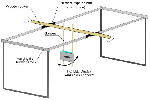
To make the display, we need two axes of motion. The first axis consists of a row of LEDs where the light moves back and forth (more on that in a minute). For the second axis we take that 1-D LED display and rock it back and forth like a pendulum on a simple bearing. To hold the pendulum up, we used a hanging file folder frame, made less slippery with some electrical tape, and a wooden dowel. The LED display hangs down below this wooden dowel on a couple of skinny bamboo skewers. One thing to note immediately is that the pendulum frequency is finely tunable by moving the mass (i.e., the LED display) up and down along the skewers.
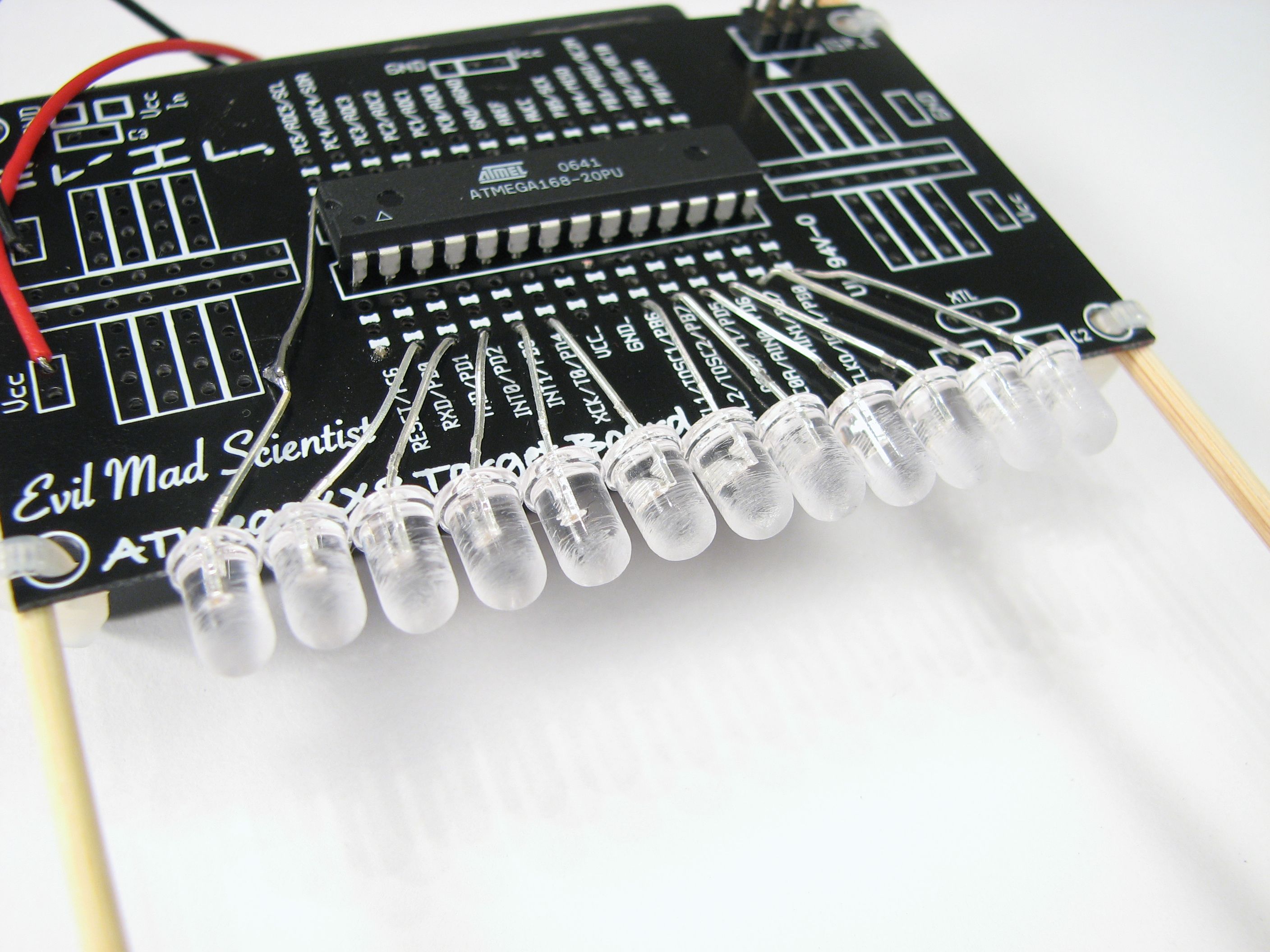
For the LED display, we used an ATmega168 AVR microcontroller on a little board with 12 blue LEDs. You could very well do the same thing with a genuine MiniPOV instead, but we wanted a few more LEDs (12 instead of 8) and pointing at the edge. Much like in our tennis for two project, we built this up on one of our business card printed circuit boards. The circuit simple enough that even that board is overkill unless you happen to have a pile of them lying around; it’s just our version of the minimal target board.
We took 12 regular blue LEDs and sanded them to give a nice diffuse surface visible from any angle. We hooked their anodes (+ sides) to pins C4, D0-D7, and B0,B6, and B7 of the ATmega168. Getting them in a neat row is the biggest challenge here.
On the back side, we wired up the cathodes (- sides) together and then through a 50 ohm resistor to ground. Power for this little board was from a 3xAA battery box that we stuck to the back side with foam tape. (That heavy battery box is actually good for this design because it provides a nice weight for the pendulum!)
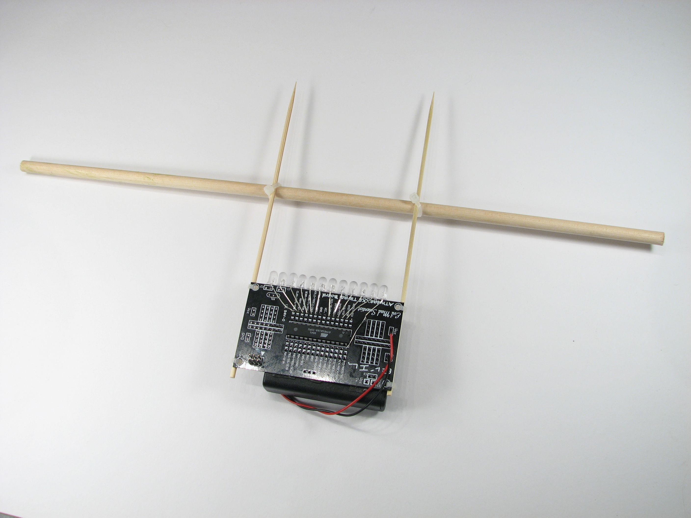
Our little LED board is attached by a the wooden skewers to the wooden dowel now. Everything is held together with cable ties which makes it easy to slide the board and adjust the effective length of the pendulum, tuning the frequency.
The final step is to program and test microcontroller. The firmware for the AVR is released under the GPL. You can download it here (11 kB .ZIP file) and install it through your favorite interface. (If you’re brand new to AVR microcontrollers, back up a step and start here.)
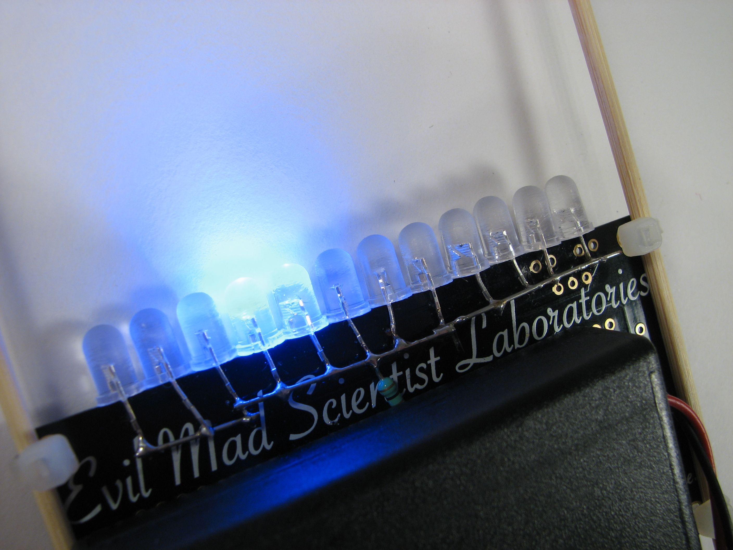
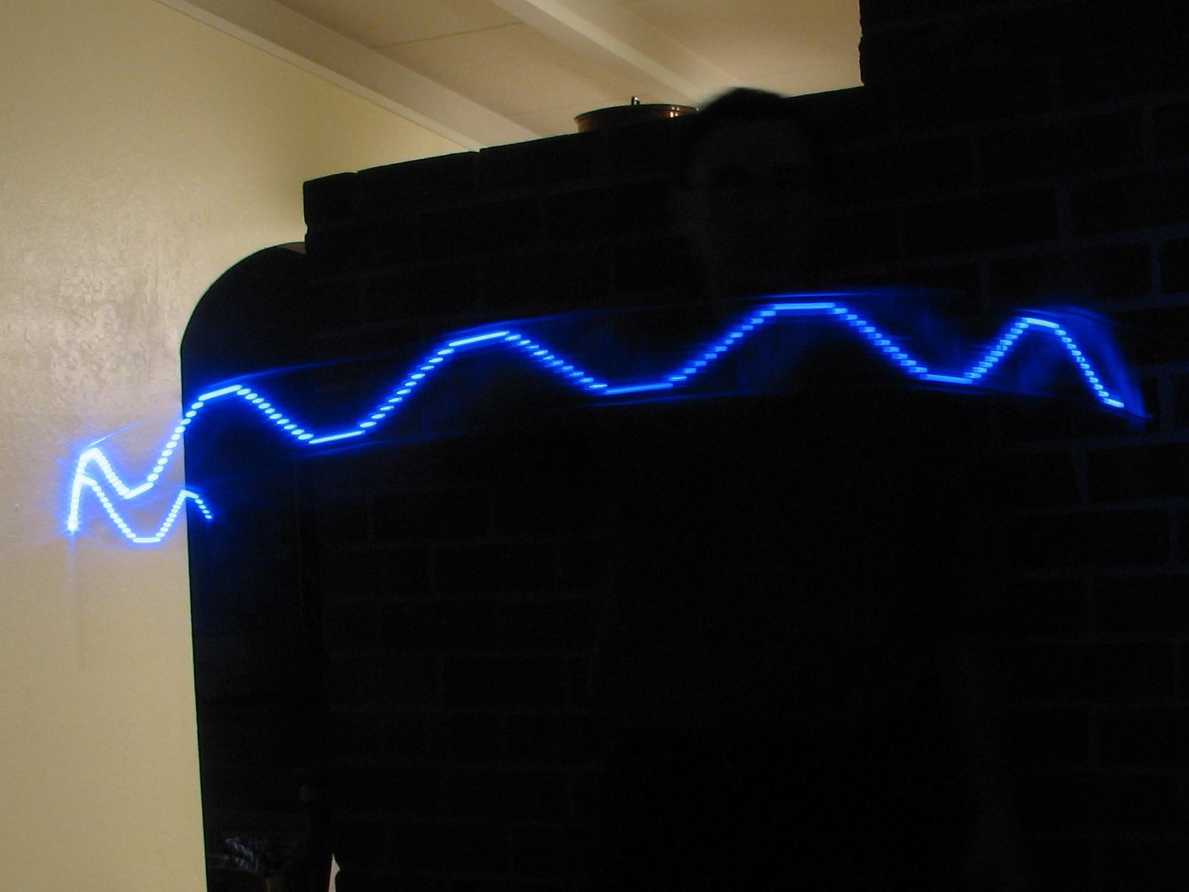
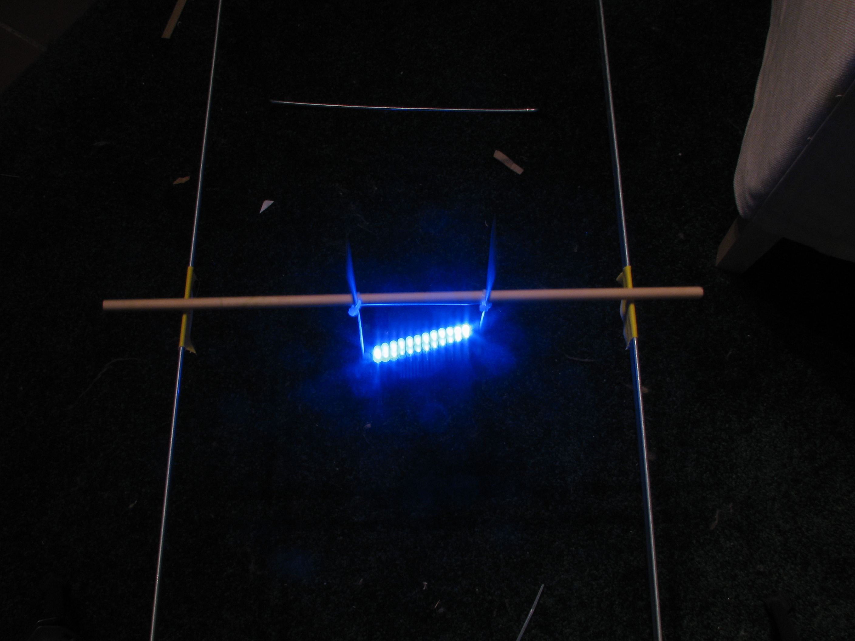
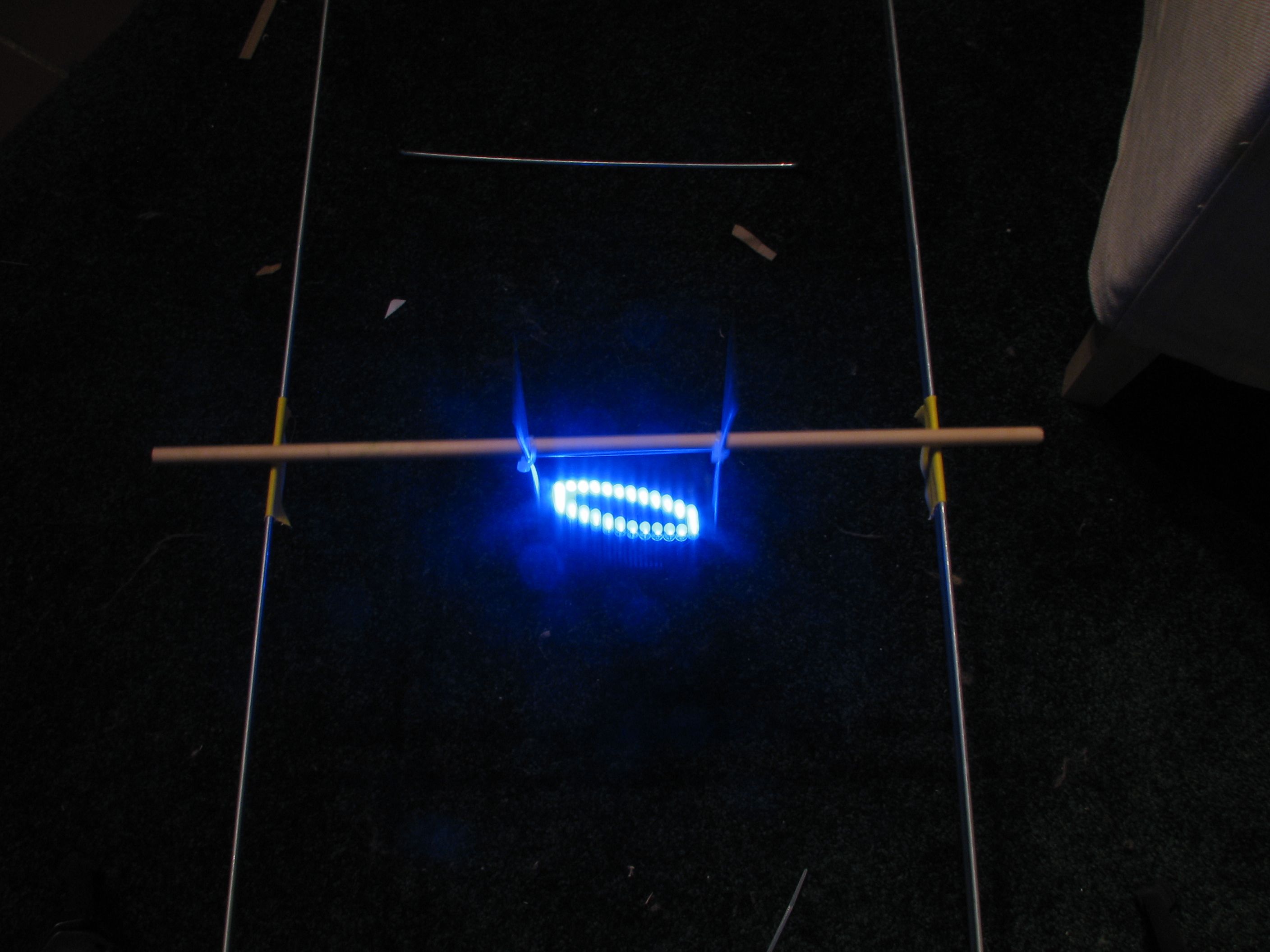
If it works correctly, it should move the “lit” LED back and forth in a true sine wave (true but very low resolution!) about twice a second. You can test this by moving it during a long exposure on the camera:
And, with that working, you’re ready to put it on the hanging file folder frame and try it out. There are two ways to adjust the two frequencies. For one axis you can reprogram it, changing the frequency, and for the other, you adjust the position of the skewers. (There’s plenty of room for improvement– one useful upgrade from our basic design would be to add a couple of buttons that would allow on-the-fly frequency adjustments.)
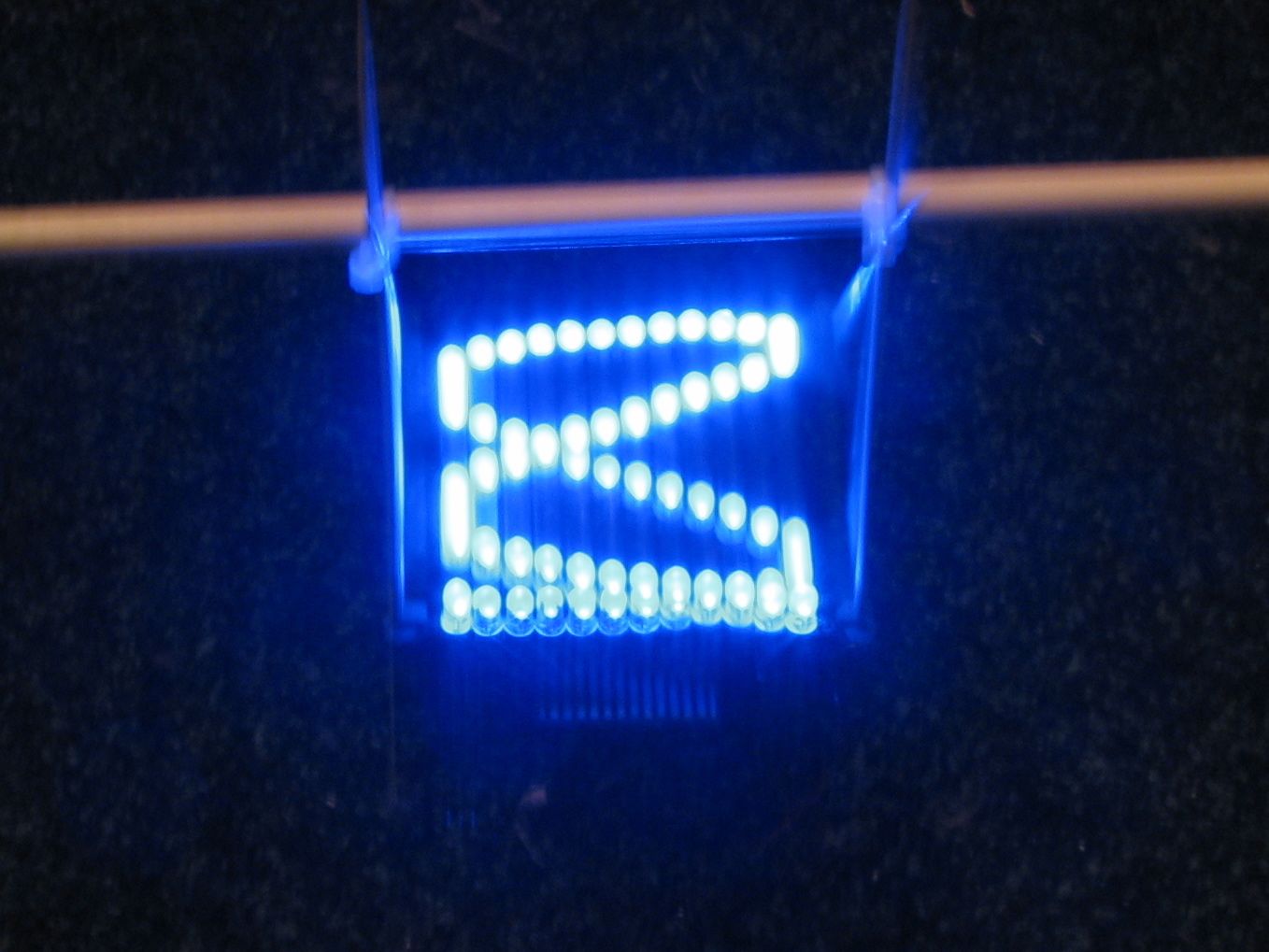
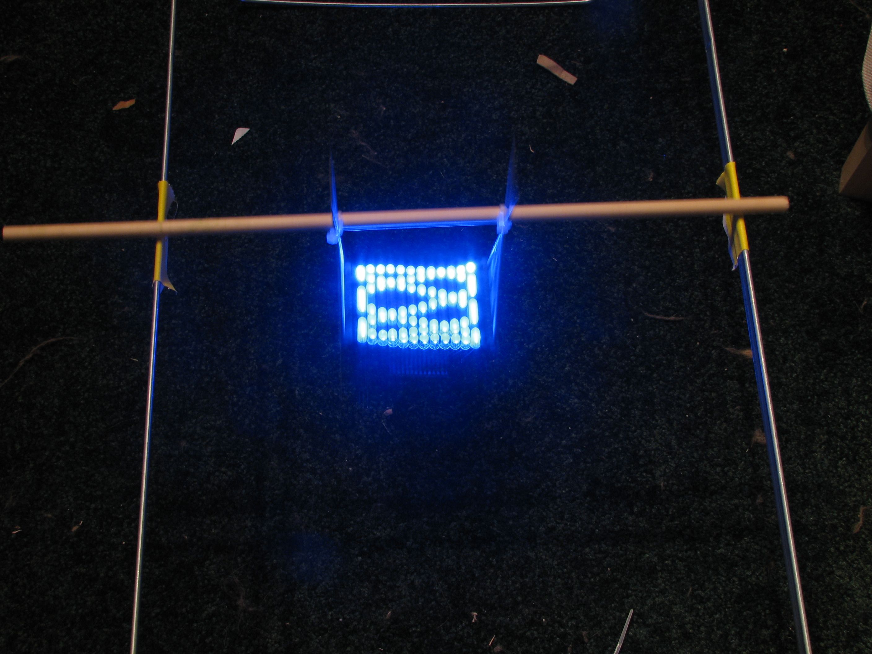
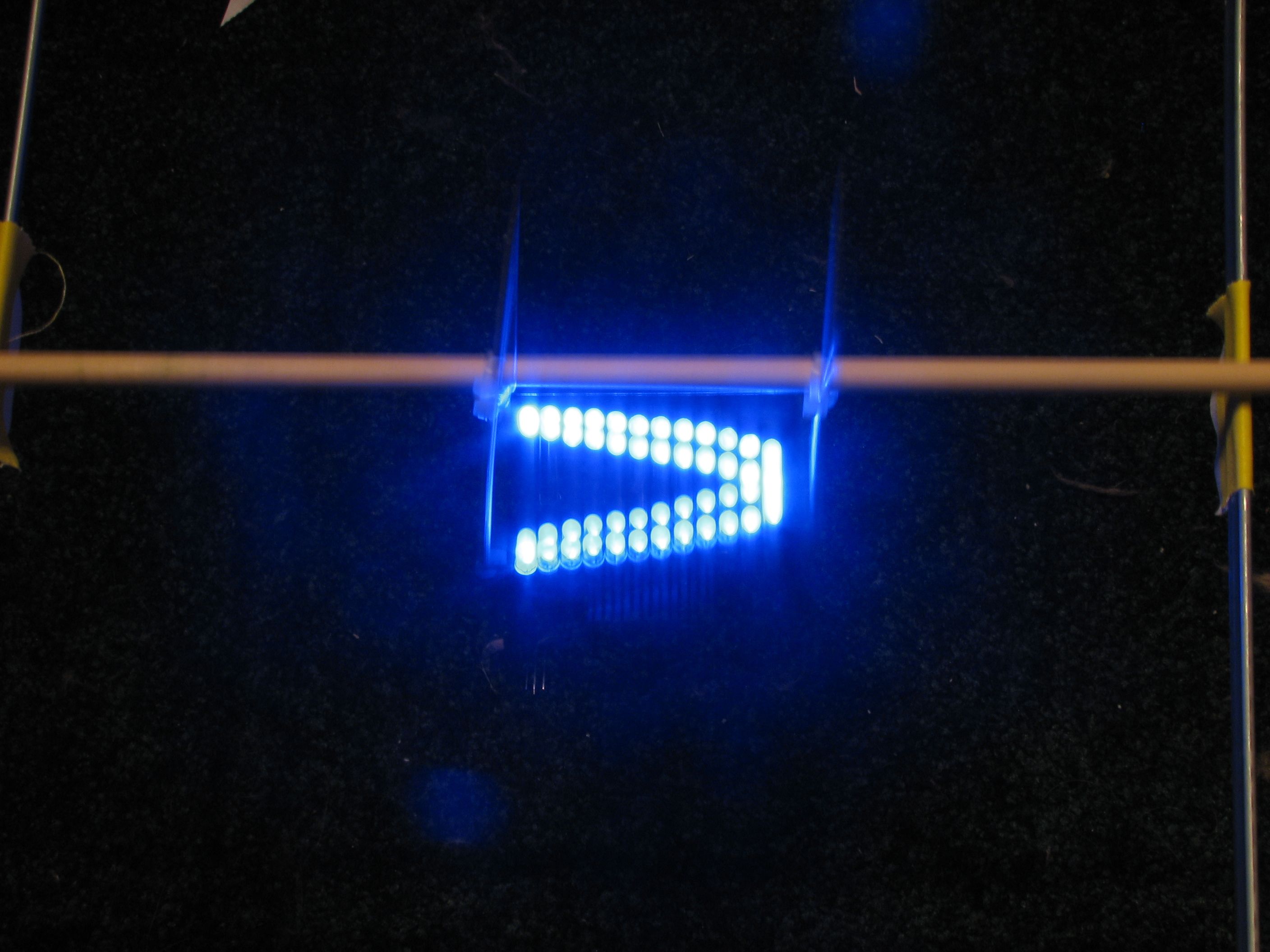
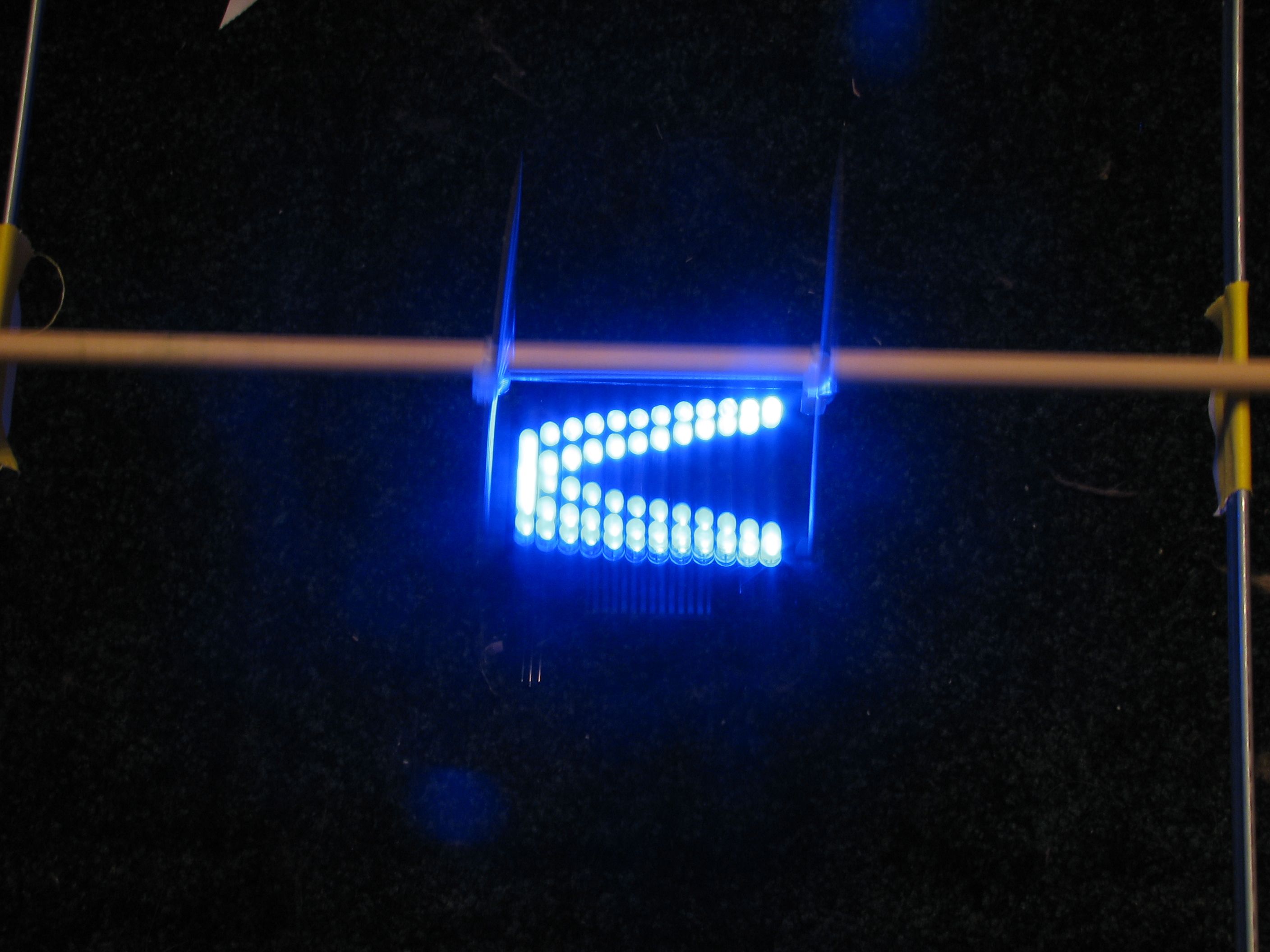
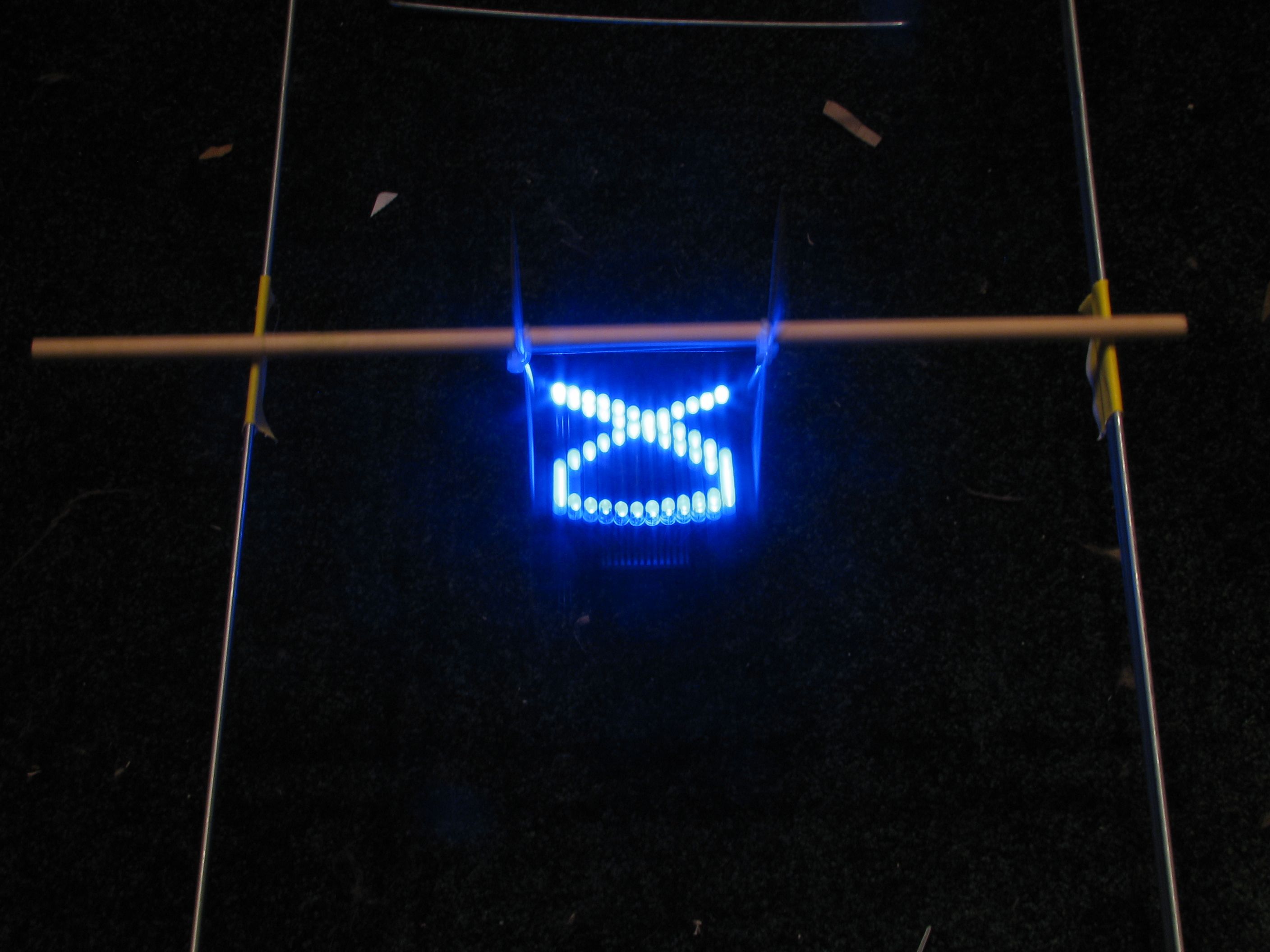
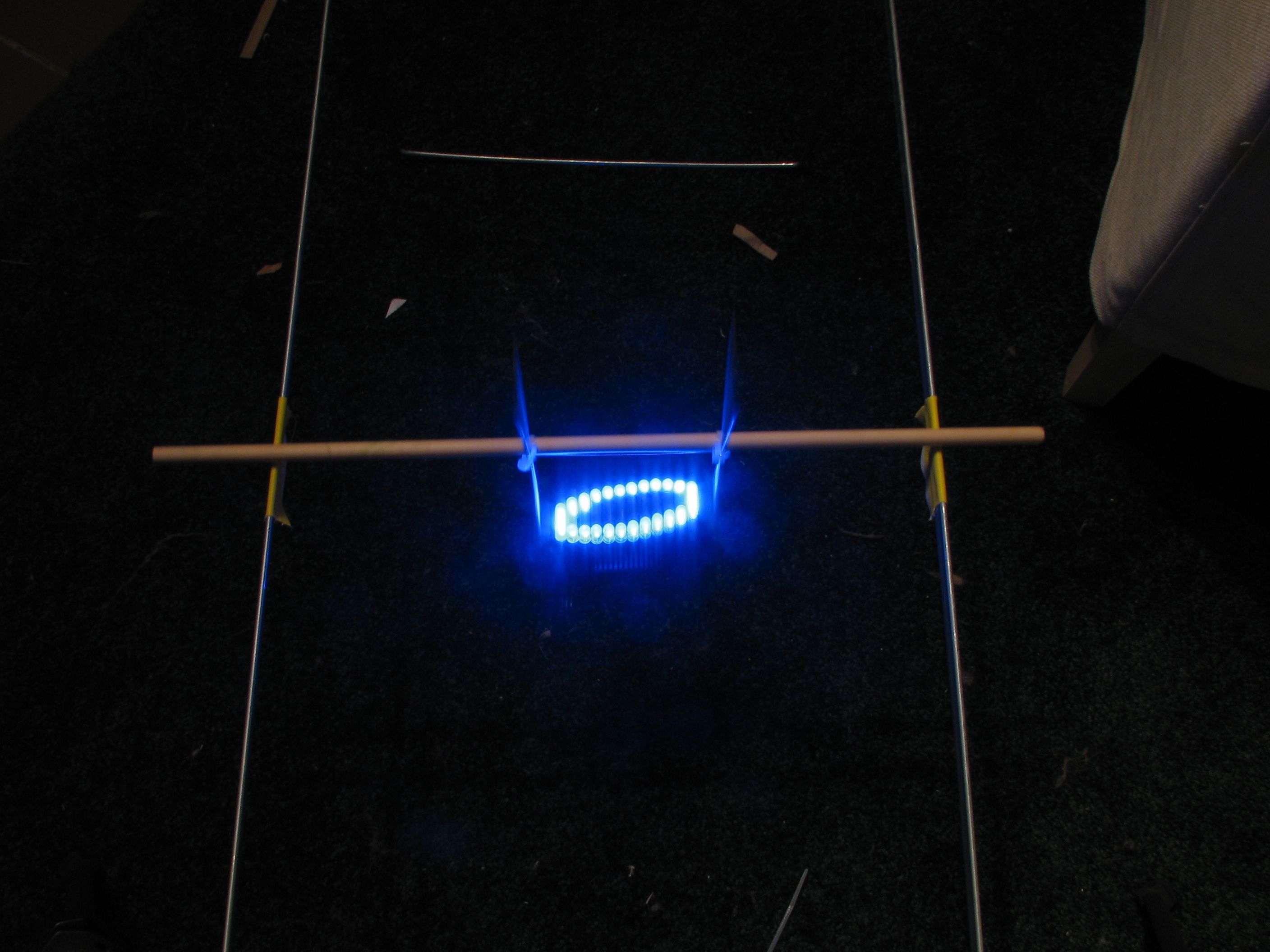
The images that follow are from a few different settings of both frequencies– just some of the interesting patterns that we found in a few minutes of playing around with it.

Finally, we mentioned that it was nice to have something that you can hold in your hands. This actually works very well (except for photography!) if you ditch the hanging file folder frame and just rock it back and forth in your hands on the dowel:
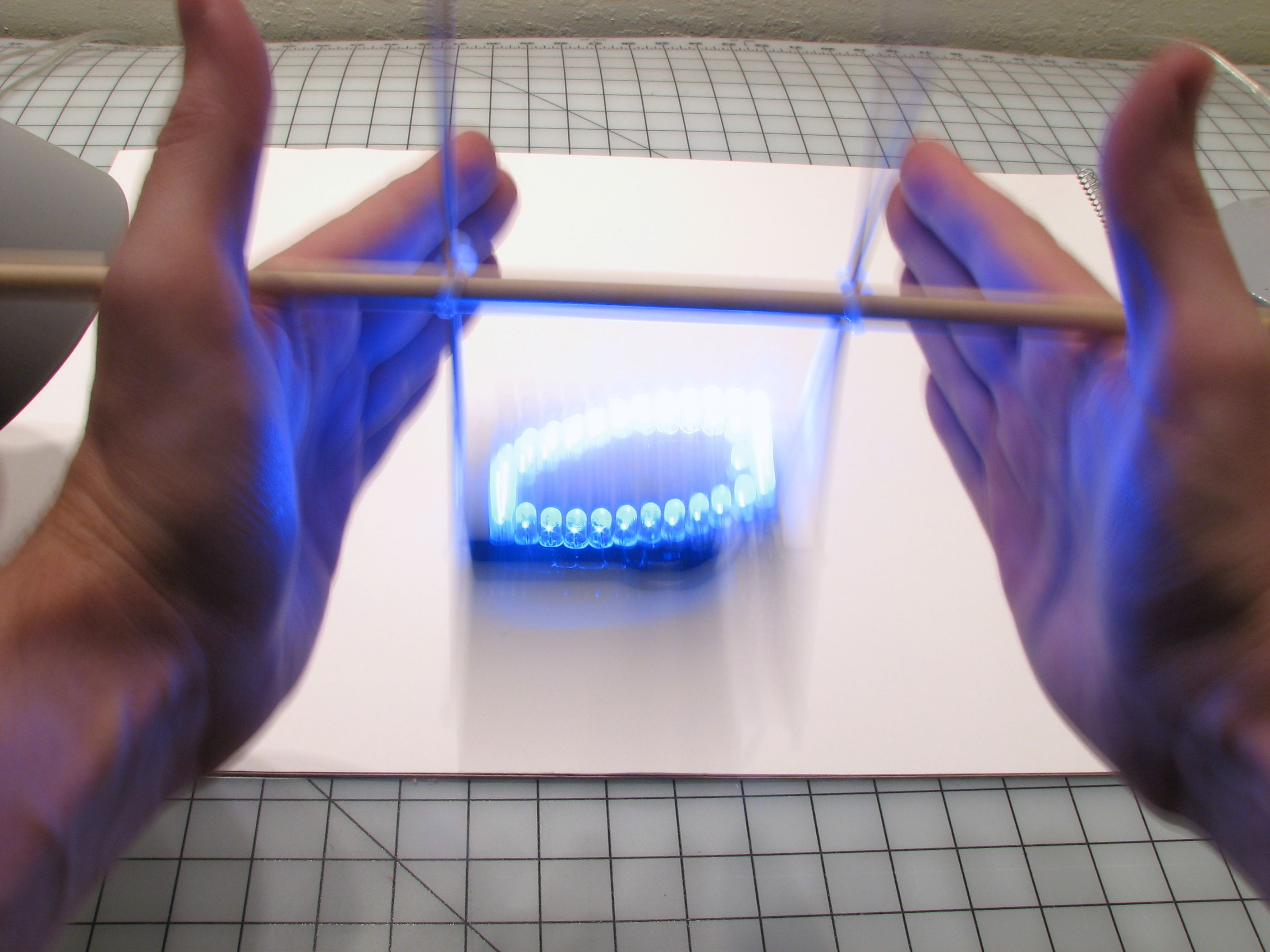
With a little practice, you can resonantly rock the pendulum back and forth, tune the length, and really hold that Lissajous figure in the space between your hands. Your turn?
…pondering a mechanically scanned digital O’scope
1) run an analog signal into one of the A/D pins
2) write some code to light 1 LED based on the value read from the A/D
3) …
4) Profit!
Sure. The difference is that a proper scope can scan the horizontal position in some microseconds (or less)– a feat you’ll never achieve mechanially.
—
Windell H. Oskay
drwho(at)evilmadscientist.com
http://www.evilmadscientist.com/
Two words: Lissajous earrings.
I know you want to do them.
What did you have in mind? I imagine that a tiny CRT is out of the question….
—
Windell H. Oskay
drwho(at)evilmadscientist.com
http://www.evilmadscientist.com/
More like a slender LED string with a circuit to scan up and down sinusoidally. As the wearer’s head moves the string would swing pendulum-style.
Can’t be harder to do than this.
Sure, that could be done. The only issue is how heavy the battery would be… it could get a little ungainly.
—
Windell H. Oskay
drwho(at)evilmadscientist.com
http://www.evilmadscientist.com/
For a school project last year, I’ve made a lissajous-projecting device consisting of a laser and 2 tone generators (set between about 15-60 Hz) hooked up to 2 small electromagnets (think small relais magnets). The electromagnets pulled/pushed 2 rare earth magnets, which were glued onto pivoting mirrors (one for x-movement, one for y). A laserbeam went from mirror X to mirror Y, and the magnet vibrations caused lissajous figures to appear at our projecting surface (in our case a wall, 20 meters ahead).
Lissajous figures are a simplified version of what MythMathFilms (disclaimer, a friend) calls kymotropes on YouTube. They’re made with an oscilloscope in x-y display mode and multiple frequencies combined for both directions.
With an oscilloscope, a lissajous figure is a kymotrope with only one pure frequency presented each to the x and y axis.
A couple interesting ones are – Teslaplasmic Entropy and Flow of Life
Bill
The could be very interesting if combined with a base patterned after those electromagnetic assisted desktop pendulum/mobile things that were all the rage 10-15 years ago and probably still can be found in places like spencers. Either that, or using an eccentric / crank arm system running on battery power to oscillate it continually.