


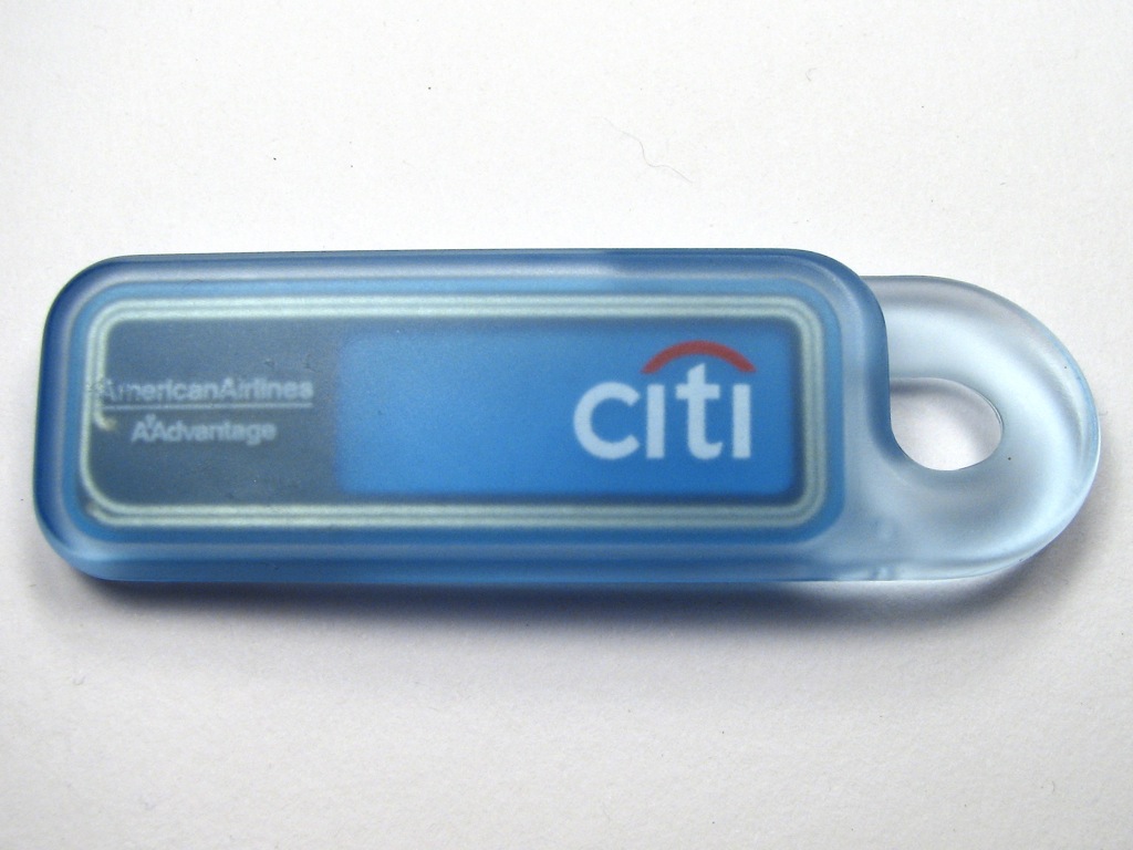
The PayPass is an RFID version of the MasterCard credit card. It is often available as a keychain “fob,” like the one shown above.
This particular one is from Citibank and is– as far as I can tell– a free optional addition to any Citibank Mastercard account. These have been in the wild for about a year now, and seem pretty handy. The obvious downside is that the RFID readers are far from ubiquitous. Still, things are improving and there are now quite literally dozens of places where you can use them.
From a hardware perspective it’s easy to see that this fob consists of the RFID element itself encased in a big block of plastic. And of course, plastic can be removed.
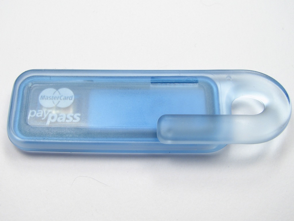
From the outside of the fob, it’s really hard to tell what’s on the inside. They’ve left just a tantalizing blurry window to see that there’s a chip in there. So, that’s the “before” picture.
The active circuitry inside the RFID keychain is potted into hard plastic, which I’m guessing is polycarbonate. To gently remove the circuitry from the inside, we placed the fob into a steel bowl filled with acetone, and let it sit for 24 hours. We have already described this procedure in some detail, in the context of extracting magnets from cheap toys, so it isn’t really necessary to go into further detail about that. The basic idea is that the plastic case simply dissolves away, leaving only the RFID element. It’s a gentle process that leaves the parts that we care about intact. Here is what is left:
What we have is a tiny printed circuit board with a dark blue solder mask. The traces on the circuit board are gold. One one side there is a simple and large antenna, consisting of two loops on the circuit board. The size of this loop antenna sets the scale for the whole device.
On the other side of the printed circuit board are two capacitors and the chip itself:
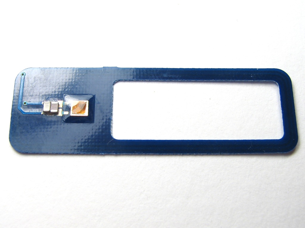
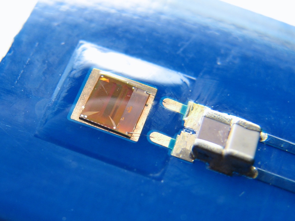
Closer up, we can see the RFID chip, which is held under a blob of clear potting compound– an epoxy that did not dissolve in the acetone. It is attached to the circuit board with a pair of wire bonds.
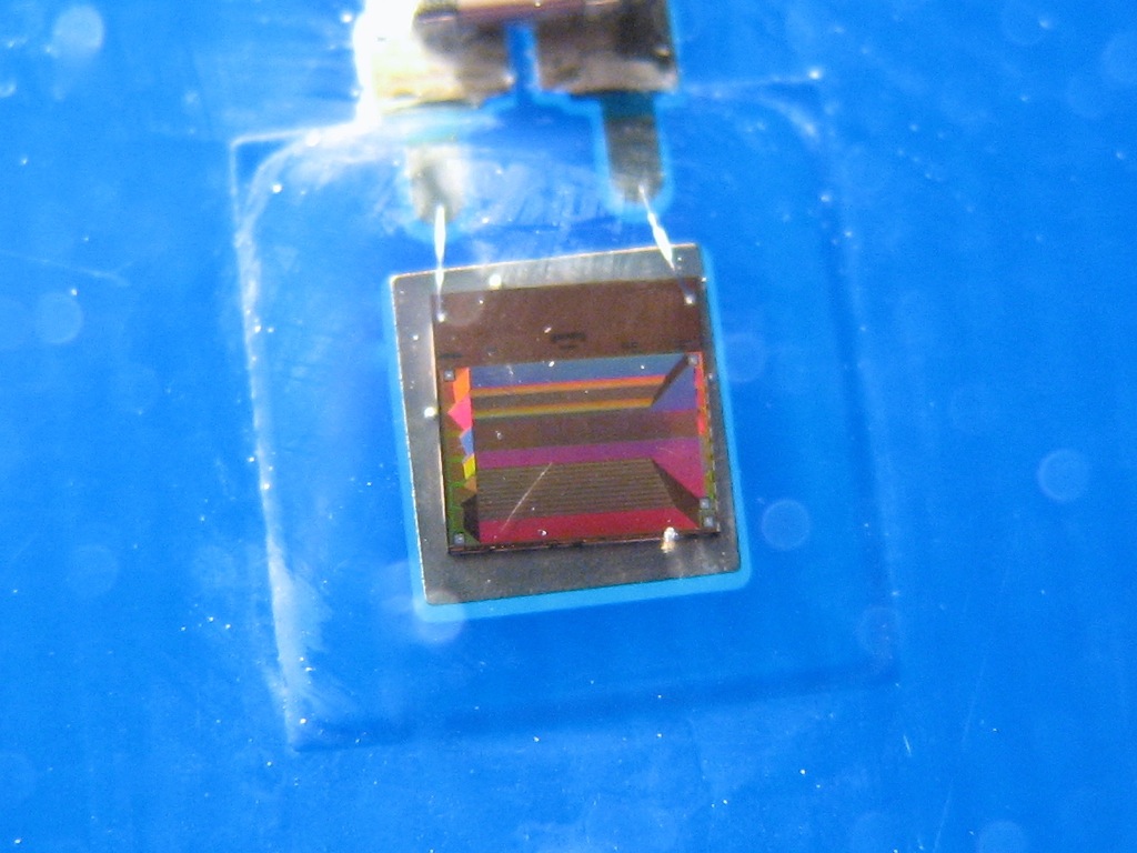
The chip itself is really quite unusual. It’s actually fabbed as an RF device with a huge number of turns of wire– possibly as a planar RF transformer. Viewed with the light from some angles, you can really start to make out the structure of the chip. (Alternate view here.)
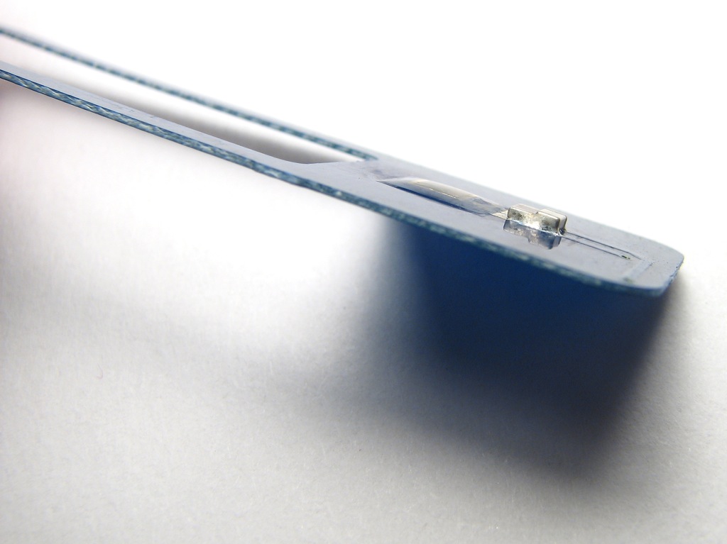
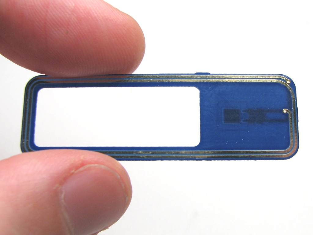
One interesting thing is that the circuit board is incredibly thin– approximately 1/4 the thickness of standard 1/16″ circuit boards, which happens to be pretty close to the thickness of a standard credit card.
It’s flexible and fairly translucent. You do need to be a little bit careful because ceramic capacitors (like the ones on this board) have a tendency to break if you bend the board that they are soldered to.
Of course, we can now give our RFID element any kind of a case mod that we see fit. One thing that would be easy to do is just to embed it in the side of a wallet. You could also embed it in any one of the millions of things that have become USB thumb drives in the last few years.
You can also image getting a little more serious, putting your own loop antenna on, and changing the geometry somewhat. Maybe you can make your own PayPass wristwatch.
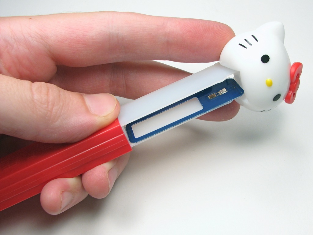
For the sake of absurdity, here is one overly large, silly, and seriously impractical case that you could use: it’s “Hello Credit.”

If you come up with other interesting mods for these guys, we’d like to see them. Please add them to the Evil Mad Science Auxiliary on Flickr.
You could attach it to a normal sized credit card.
I thought of that too; it would be rather ironic, wouldn’t it?
The funny thing is that they actually do make credit cards with the RFID thing built in. So… why don’t they just send those things?
—
Windell H. Oskay
drwho(at)evilmadscientist.com
http://www.evilmadscientist.com/
Wait, that outer ribbon works like an inductor of some sort? If this chip is powered by some sort of induction principle you could use some sort of transistor (MOSFET or JFET for no current drain?) to switch on an external circuit. I’ve never played with RFID so I’m not sure how it works. I wonder if attaching another circuit would affect the readout as well. Just having a light flash when the card is being used could actually be somewhat useful. Maybe make it so if you don’t hold down a button when you have the card read it could emit a sound, so if someone tried to sniff the card data without your knowing you’d be made aware of it. An RFID alarm so to speak. Passing through store security paddles may set it off though.
That certainly could be done if you added an external battery (e.g., coin cell) to power your external circuitry. The trigger to the the external circuit could be as simple as buffering the signal to the antenna with a high-impedance op-amp and ac-coupling that input.
—
Windell H. Oskay
drwho(at)evilmadscientist.com
http://www.evilmadscientist.com/
I meant to imply the external circuit was being powered by something else. I doubt you could pull enough power off that antenna/inductor to do anything useful, not to mention without interrupting the operation of the RFID chip.
I’m not sure exactly how these work, but with a high impedance op-amp tied to that line I wonder if you could log the whole transaction somehow. If signals between the reader and the card are conveyed through that antenna/inductor; a fitting op-amp and an external circuit with a UC could do the trick. Just matching clock rates could be next to impossible though. And if the signals are some sort of analog you also have to worry about the speed of your ADC. Actually the more I think about it the harder to pull off it sounds.
Edit: researching the subject before I post about it helps make me not look stupid: http://en.wikipedia.org/wiki/Rfid#Passive. So the signal is going through that antenna. Discerning the transmit signal from the scatter back signal alone could be a monumental task. Now I’m sorry for suggesting logging as a hack. Too much work for too little reward. Just getting a LED flashing along with the IO from that antenna would be cool though.