


What do you get when you mix a 1970’s style analog chart recorder, an 8-bit microcontroller, and a Fisher-Price Doodle Pro? A truly 21st century toy: An analog PlotBot with e-paper display technology!
For the overview, check out the video introduction (YouTube).
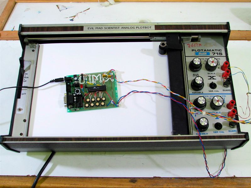
Our machine is based around a vintage analog X-Y data recorder. Its original purpose in life was to perform basic laboratory data collection, plotting two voltages against each other, and was one of the primary tools for that purpose right up until computers took over that job in the 1980’s. Because they were once so common and are now generally obsolete, it’s quite easy to get one of your own. There are usually several under $50 on eBay at any given time, and that’s where we got ours. Ours is an Allen Plotamatic 715, which holds a regular sized sheet of paper, takes tiny felt-tip pens, and has stylish faux-wood trim.
One of the awesome things about a true analog plotter is that is uses analog servo motors, rather than stepping motors or digitally encoded servo motors, to move the pen. (This is a little bit like the difference between an analog and digital oscilloscope: the analog scope trace is actually controlled by your input signal, whereas you don’t know what the digital scope does to your signal!)
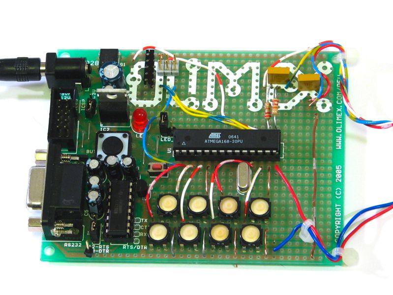
To change it from just being a plotter into being a PlotBot, it’s now controlled by a single microcontroller. We used an Atmel AVR 8-bit microcontroller, specifically the ATmega168. (And we’ve made the source code available for download!) In the photo here, you see it sitting on an Olimex development board, which provides power and a place to hook up connections to it. We also added some buttons that can be used as keys to trigger different plotting programs stored in the microcontroller.
The other major modification that we’ve made is that we’ve replaced the pen and paper with what seems like out of reach technology: an inexpensive and readily available e-paper display: the panel from a Doodle Pro.
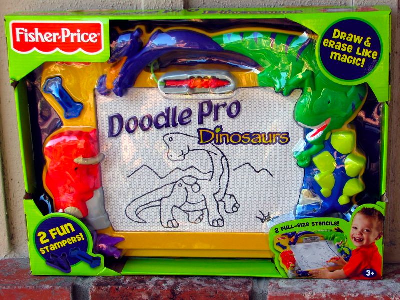
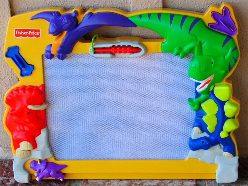
The Doodle Pro is a descendent of the Magna Doodle, a classic children’s toy dating to 1974. (I’m not sure what makes this a “Pro” anything, however.) It uses a simple magnetophoretic display, where ferromagnetic particles are suspended with near-neutral buoyancy in an opaque, viscous white liquid. Using a magnetic stylus, you can attract the black particles to the top surface, or with a magnetic “eraser” on the bottom side, pull the particles away, leaving only the white liquid visible. You can read more about its design at How Stuff Works.
Why did we go for the dinosaur model? It was the cheapest one of the large size available at Target when we went shopping– almost certainly because it was the only one without licensed characters decorating it!
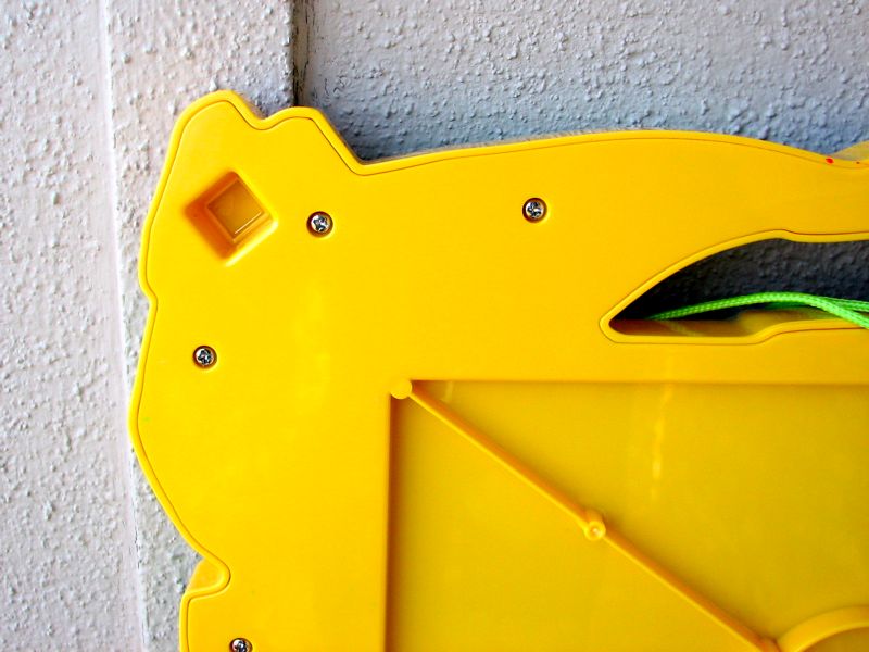
Although the frame is abnormally shaped, the panel inside is a regular rectangle, a little bit bigger than you might guess from the frame– those dinos do get in the way. The frame is held together with screws and is fairly easy to disassemble. Be forewarned however: the two smaller sizes of Doodle Pro that we’ve seen are made by insidiously fusing the plastic frames together, and disassembly is a destructive operation.
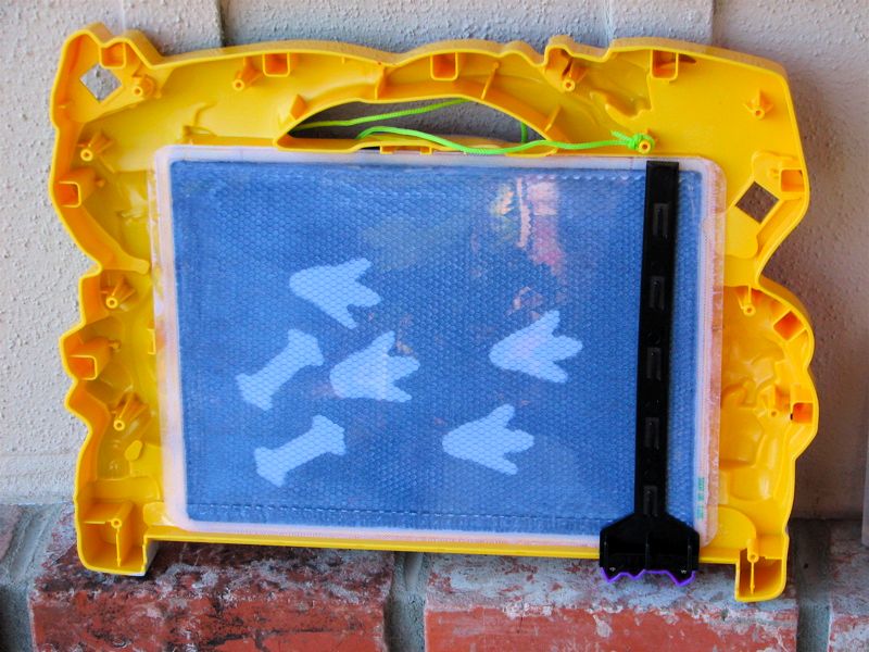
With the back frame of the Doodle Pro removed, you can see the eraser mechanism, which is the black piece of plastic and holds a thin rubber magnet which can be moved back and forth across the screen. The bones and footprints look like black marks on the other (front) side of the panel, and are made with magnetic “stamps” that came with this dinosaur-themed set.
Perhaps the most challenging part of the disassembly is yet to come: the display panel is held into the frame by industrial-strength sticky tape and glue, and it takes some work (and some clean up) to get it free.
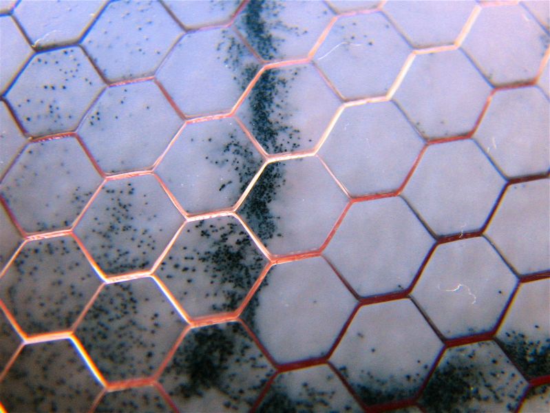
Here is a close up view of the display panel itself once it’s been removed from the frame.
For me, seeing this was like seeing the inside of an etch a sketch for the first time!
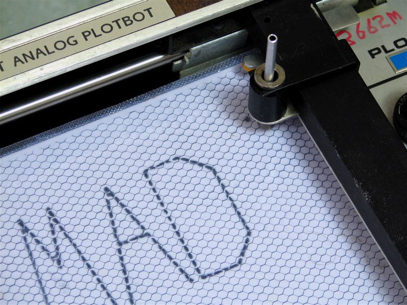
Normally, when you are looking at one of these toys, it appears to have a black hexagonal grid under the the top surface. With backlighting like we have here, it becomes obvious that this honeycomb structure is actually part of the same piece of clear plastic as the front and back surfaces of the panel.
You can clearly see the black magnetic particles, which are either against the near or far surfaces of the panel, and therefore visible or not. Remarkably, the total thickness of the panel is only about 1 mm, so the fluid must be remarkably opaque. One of the curious side effects of the panel being so thin is that it is actually much easier to erase the screen thoroughly with a weak magnet than with a strong magnet. The weak rubber magnets that come with the sets slightly attract the magnetic particles to one side and do a good job of erasing. If you instead use a strong neodymium magnet, the magnetic particles line up along rigidly along the field lines and are visible from both sides of the screen, rather than being simply attracted towards the back side.
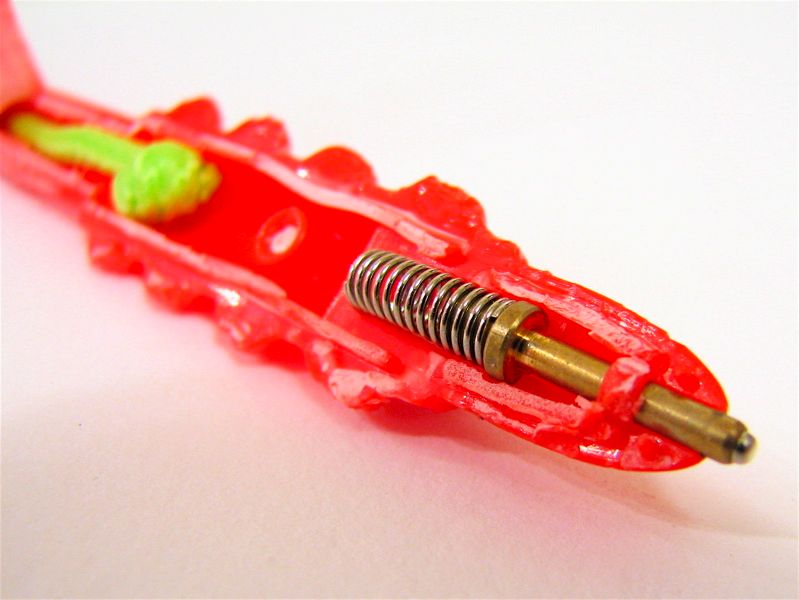
On the left is the what the inside of the Doodle Pro stylus looks like. The tip is spring loaded, and contains a small magnet (Alnico?) at the tip, held in a brass adapter. The green string on the back side tethers the plastic stylus to the display panel. Again, it turns out that a fairly weak magnet, like the one that comes with the set, is better for writing on the display. Using a stronger magnet attracts additional magnetic particles from further away and leads to a blurry picture.
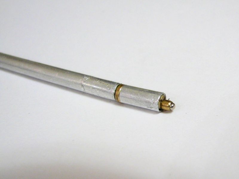
In order to adapt the stylus to fit into the penholder of the PlotBot, we removed the tip from the original stylus and constructed a tiny body around it, using a couple of small pieces of aluminum tubing. A few layers of masking tape were later added around the middle to give it a more snug fit into the pen holder.
That’s it for the construction, and so we merely need a program on the microcontroller in order to see what the PlotBot can do. The starting point for the firmware was our Quick and Dirty D to A tutorial, where we took the pulse-width-modulation outputs from two hardware timers and averaged them with a low-pass RC filter. That allows us to produce slowly-varying analog output voltages that we send to the X-Y inputs of the plotter. A third output channel from the microcontroller is used as a logical signal to drive the pen-lifting mechanism of the plotter. The code is written in C and is based around a simple using three commands for plotting: moveto(x,y), penup() and pendown(). With these simple commands we’ve been able to program the PlotBot to write out text or draw graphics. We’re distributing the code, including a couple of examples, under the GPL and you can download it here (45 kB .ZIP archive).
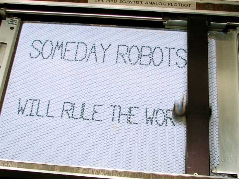
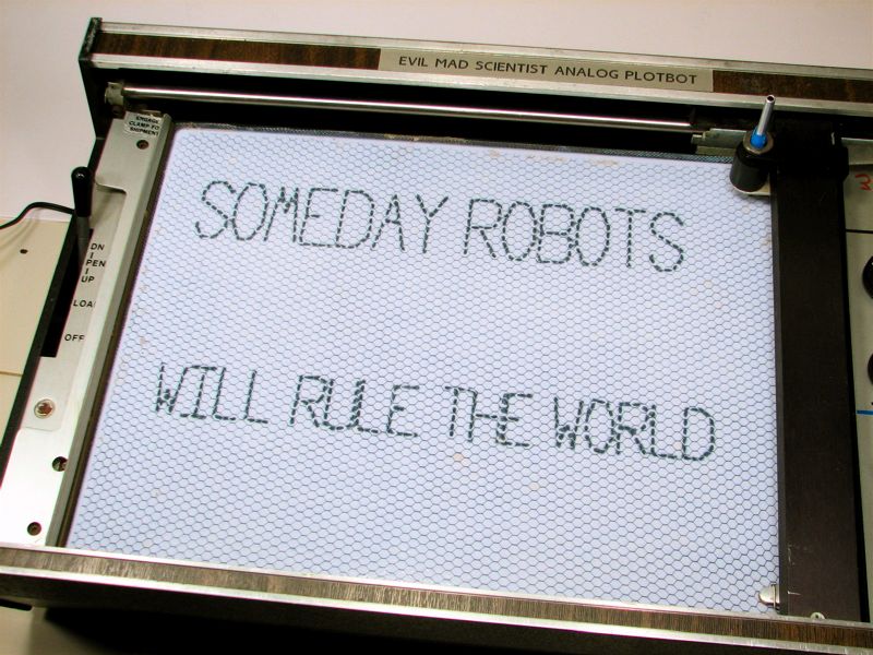
So, how does it work? Pretty well actually.
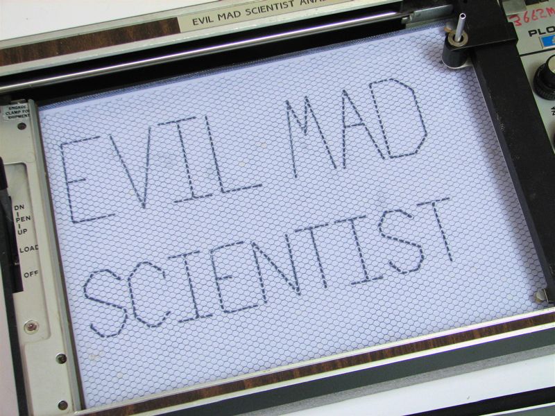
Here is what the output from the PlotBot looks like, in the case of writing some simple– and entirely randomly chosen— text. =)
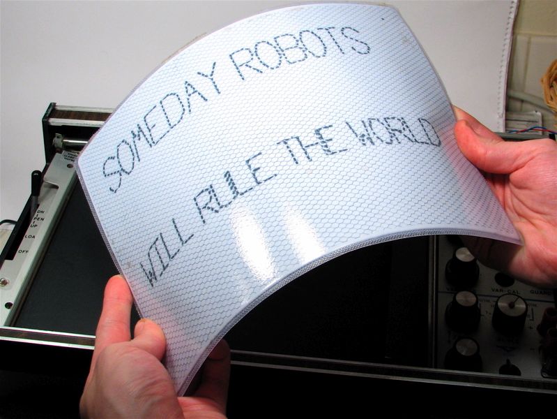
So is it really e-paper? It turns out that it is. Strictly speaking, this is a magnetic display, not an electronic display. However, magnetic fields can be generated with electronics, so that point is negotiable. Much more importantly, it has all the hallmarks of electronic paper: it is a high-contrast, daylight-readable display that reflects ambient light much like regular paper. It is flexible, erasable, and it requires no electricity to maintain an image on the screen. And as it turns out, variations on this technology are actively being explored for use as electronic paper, as evidenced by a growing number of patents on the subject.
This particular one happens to be a big and flexible e-paper display– not bad for fifteen bucks!
So, what about graphics? The primary limitation to using small microcontrollers like these is that there is typically very little memory. The entire program to write the text strings that you’ve seen above fits into about 6 K of memory, but graphics tend to take a lot more memory. That’s one of the areas in which larger microcontrollers, like the one in the MAKE Controller, really shine. Over at Make, Bre Pettis made a great drawbot based upon the MAKE Controller, and the project documentation includes a review of some other techniques for making drawing robots. The project is documented in three parts (1,
2, 3) and is certainly a useful resource if you’re building your own. (As long as we’re talking about other art robots, let’s point out that we’re also partial to the eggbot and the ArtBot as seen at FinkBuilt.)
We did implement some moderately-simple graphics that would fit within our 16 K of memory, converting a jpeg image into a set of moveto(x,y), penup() and pendown() commands. For graphics, our routine is a dumb-as-a-rock brute force rastering renderer– you can do a heck of a lot better in terms of memory usage in any number of ways, but we decided to keep it simple to make the code a little more transparent.
We started first with this picture of a 2N3904 transistor, and converted it to a
200 x 150 monochrome image:
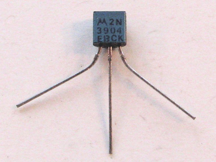

Remarkably, you can almost read the markings on the transistor, even at that poor resolution.
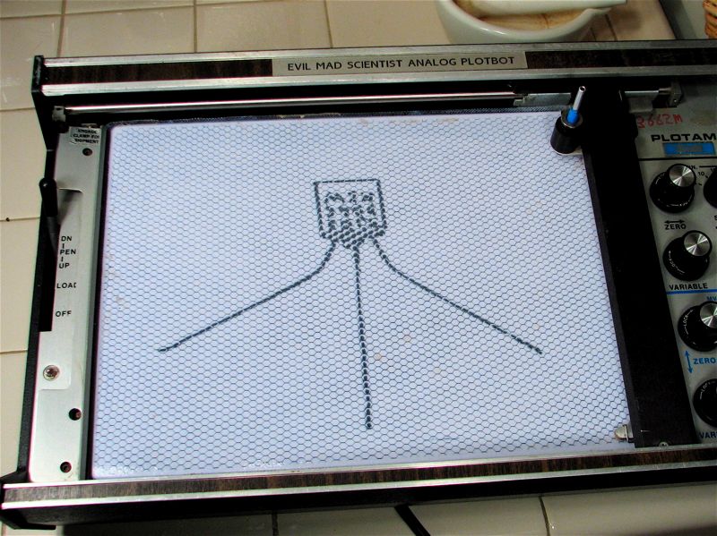
Finally, we tried a slightly more ambitious plotting job, where we took the photo of one the Lego guys from our Halloween projects and converted it to a low-res monochrome image, which we used to program the PlotBot:
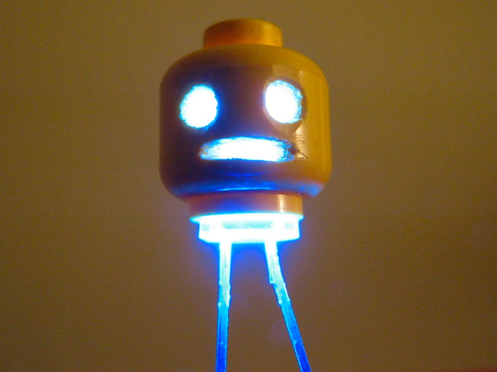

With result:
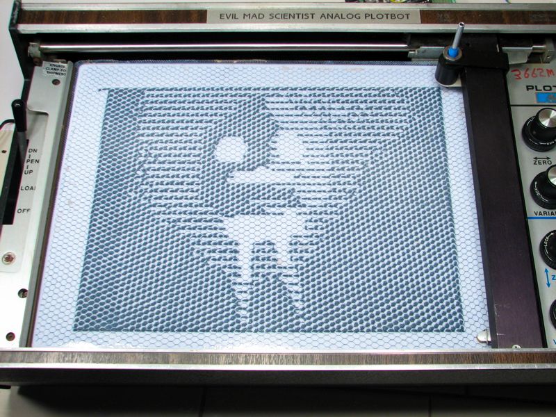
Wicked Cool!!
Thanks!
—
Windell H. Oskay
drwho(at)evilmadscientist.com
http://www.evilmadscientist.com/
This is great! So now who wants to merge the Evil plotter with a glue gun and make a rapid prototyping machine?
That’s an interesting idea, and not so far off from how a number of home-brew machines are being desgined right now. However, we’re already working on our own 3D printer at the moment– and it prints in sugar!
—
Windell H. Oskay
drwho(at)evilmadscientist.com
http://www.evilmadscientist.com/
yea but can you dremel a PCB with it?
this is very cool