


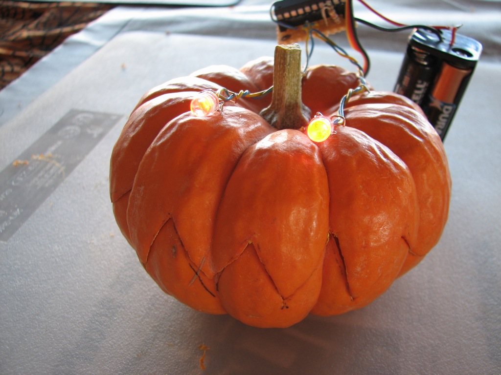


The Snap-O-Lantern is a robotic mini-pumpkin. Normally, it just sits there, in disguise as a boring old pumpkin. But, every twenty seconds he comes to life. His LED eyes turn on, his jaw slowly opens, and then SNAPS shut– and he goes back into stealth mode.
What’s inside? A small hobby servo motor, driven by an AVR microcontroller. This is a minimal microcontroller project, and is very straightforward if you happen to already have a setup for programming one. We’ll walk through the carving, setup, programming, and electronics. This is an open-source project, one of the world’s first “gpl-o-lanterns”; source code is provided.
 The first task is to carve the pumpkin. It needs to have big pointy teeth in the front, and a hinge in the back. We’ll use a simple friction hinge, and the big pointy teeth help to realign the pumpkin’s mouth when it snaps shut.

Start with a large-ish mini-pumpkin. Pick a side to be the face and draw some big pointy teeth on it using a fine-point sharpie. The ink can be removed later, if necessary, with rubbing alcohol.
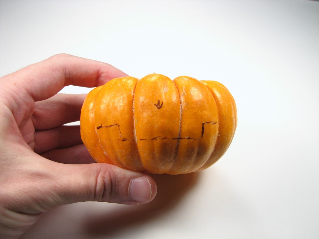
Away from the teeth, simplify the pattern to a simple cut, and on the side exactly opposite the center of teeth, mark a shape like so. This notch, an inch or two wide, will form the basis of a hinge.


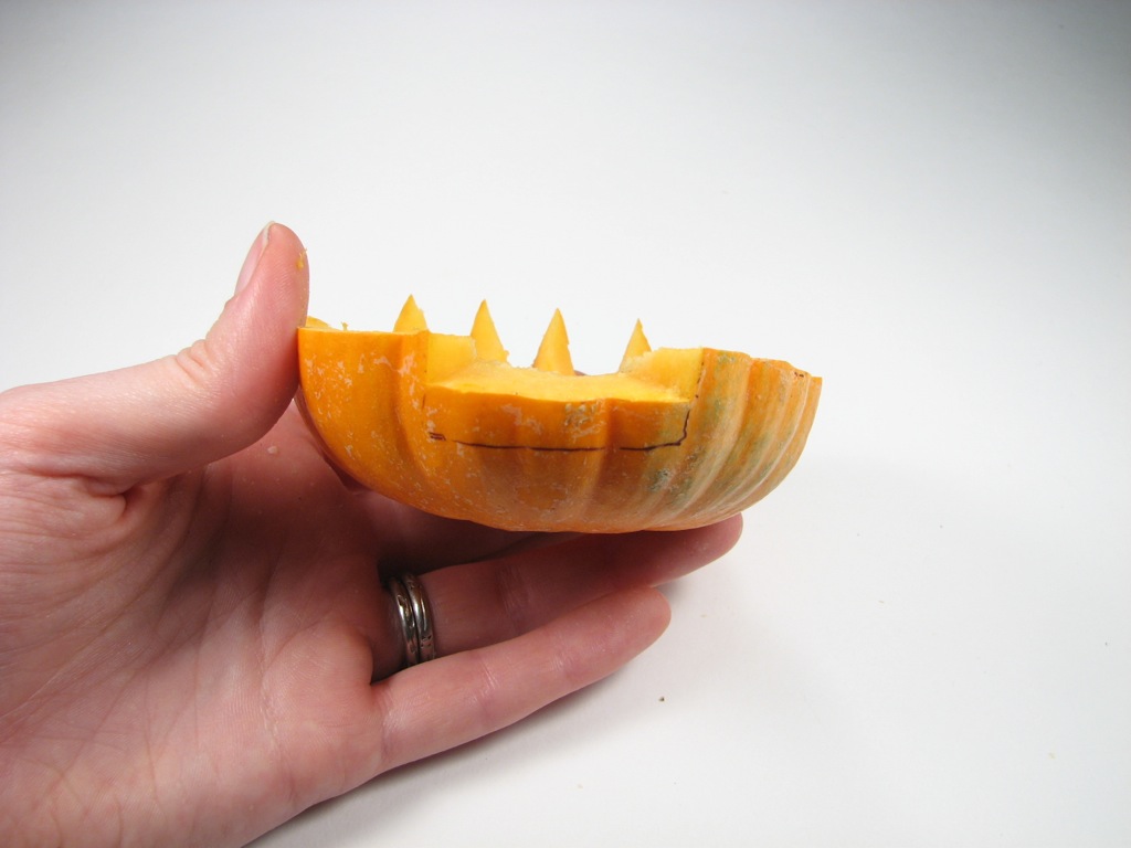
Using a very sharp knife, carefully cut along the pattern that you have made. This should completely separate the top and bottom halves of the pumpkin.


Using a spoon or other appropriate tool (like the melon baller shown here) scoop out the seeds and loose pulp from the inside of the pumpkin.
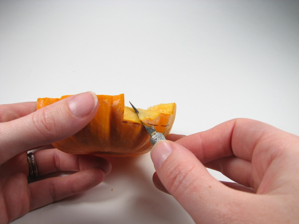


The proto-hinge at the back of the pumpkin presently consists of a wide tongue that sticks out below the top half of the pumpkin, and a matching slot in the bottom half. We want to be able to tip the lid back on that slot easily. To make this possible, we need to angle the top inside surface of the slot.
Make a guide mark below the top of the slot, and cut the surface of the notch at an angle such that the lid can tip back easily, virtually hinged at the point where the two pumpkin halves meet. Look carefully at the photos to make sure that you see where the cut needs to be added; you can always click on the photos to get a closer view.


Now it’s time to turn that proto-hinge into a real pivot hinge. (There are several other good ways to make the hinge work– if you have another way that you like, go right ahead.)
The basic idea is that we add two toothpicks to the back of the lower half of the pumpkin. The tongue and slot prevent side-to-side motion while the toothpicks prevent the lid from sliding backwards and provide friction against sliding upwards. Then, when we push up on the upper front teeth, the jaw tends to open neatly, and fall back into place when released. Insert the toothpicks as shown in the photo (you may want them a little more vertical than this) and trim them so that only about 1/2″ of each toothpick is visible.
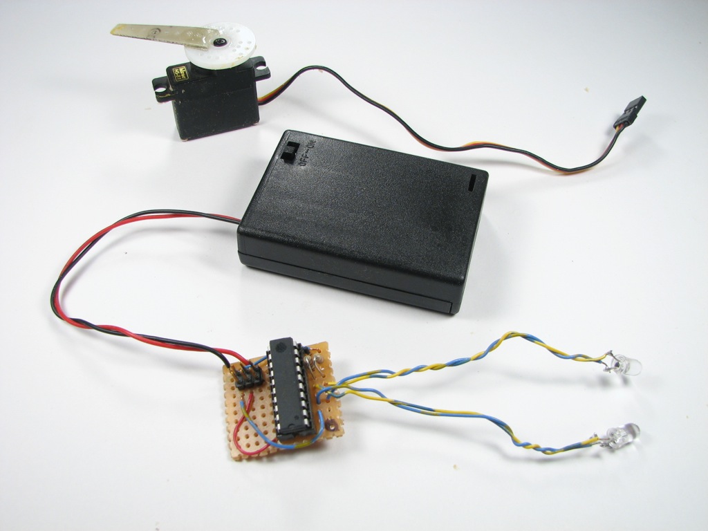
Now that we have a working hinge, we come to the electronic portion of the project. Here is the list of parts:
- 4.5 V – 5 V power source. Suggested: a 3xAA battery pack with alkaline batteries.
- RC hobby servo motor. Suggested: medium-small model such as Hitec HS-81
- Two LEDs, red, orange or yellow.
- Two 1 k resistors
- ATtiny2313 microcontroller and programming setup
- 20-pin DIP socket for ATtiny2313 (optional)
- 2×3 DIP header
- Hookup wire
- Pad-per-hole circuit board or similar protoboard
Download the firmware for the project here (12 kB .zip file). If you already have a working setup for programming AVR microcontrollers, you probably already know what to do. Unzip the file, customize the header of the makefile to reflect the programmer that you use and which port it is on, and run (in a terminal) “make all”, “make program” to compile and flash it. If you have a more specialized programming environment, you can use that instead without any worries– just make sure to copy over the fuse settings from the makefile.
If you are new to programming AVR microcontrollers, or to microcontrollers in general, start here for a great overview. (See also our list of AVR resources.) You will need a to set up a tool chain of (free, open-source) software and some programming hardware.
The rest of the parts are set up as shown in this diagram:

Wire up the battery pack, positive side to pin 20 of the ATtiny2313, negative (“ground”) side to pin 10. Use the 2×3 DIP header as a pair of standard servo connectors, where the signal sides come from pins 12 and 13 of the chip, the middle pins go to the positive end of the battery, and the other two end pins go to the negative end of the battery. Finally, two LEDs with 1k series load resistors go between pins 8 and 9 and ground. Instead of wiring the LEDs directly on the board, put them on the end of long wires so that they can be placed as eyes for the pumpkin.
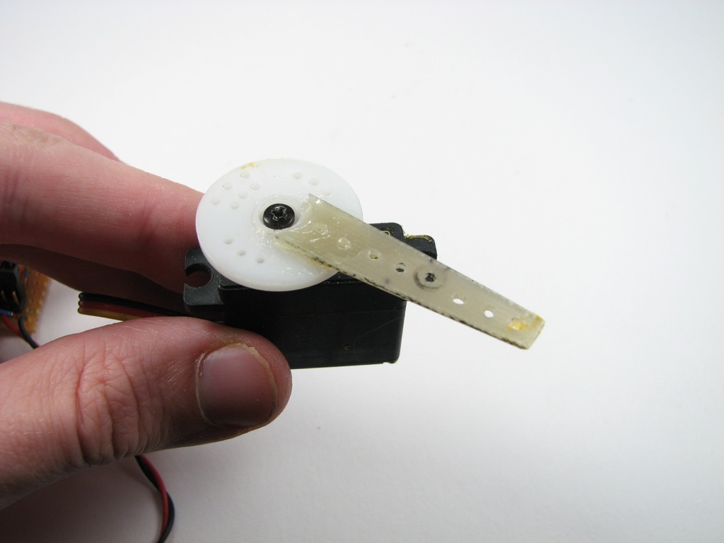
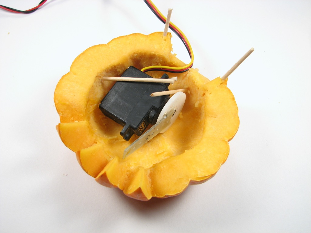
Set up the servo motor with a single long arm. If you don’t have one, you can superglue a piece of plastic to a shorter servo output wheel or horn. Connect the servo motor to one of the two servo outputs of your circuit, paying attention to the polarity. (Typically, the black wire goes towards the side that’s connected to ground.) Every 20 seconds, the LED eyes should turn on, and the servo should begin to ramp between two positions and then snap back to the original location. The two different servo outputs give two different ranges that should accommodate some variation in pumpkin size and servo throw. Set up the servo so that it can fit inside the pumpkin when it is in the “off” position and then opens up as the servo arm moves. You will need to hold the servo motor in place. Toothpicks work well for this purpose.
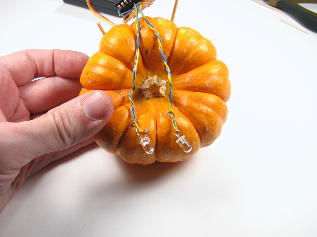

Next, attach the LED eyes. For very small pumpkins like these it can be hard to wire the LEDs inside the pumpkin itself. A good compromise is to attach them directly to the top, anchoring the wires by hand inserting staples. If you do use a larger pumpkin (perhaps pie-pumpkin sized) , you may well be able to fit the microcontroller, LEDs, and battery all inside the pumpkin itself. On the other hand, the servo will have to work much harder to lift the additional weight.
So how does it work? Nice and creepy like. Additional project build photos are here, and we’ve also put up a project video on YouTube, you can watch it there or embedded here.
—————————————————————————-
UPDATE: We released a kit version of this project, complete with a pre-programmed microcontroller, in October 2013. More information here and here.
You can find more pumpkin projects in our Halloween Project Archive.
wow thats nice.It will scare the little kids :D
It sure does! At Maker Faire they kept sticking their fingers in it to see if it would really bite them– they were absolutely shocked (not hurt, just surprised) when it did.
—
Windell H. Oskay
drwho(at)evilmadscientist.com
http://www.evilmadscientist.com/
AHAHAHAHA. I love it!
Whoa, Windell, a thought… you’ve seen how some folks have made LED coffee tables (I don’t mean yours, which is truthfully still my fave) that actually shine light THROUGH the very thin top layer of wood veneer? …I’m thinking you can hide the “eyes” inside the pumpkin lid. Maybe take a drill bit the same diameter as the base of the LED, just twisting/twirling it your fingers, and tunnel almost all the way out through the pulp to the skin. Insert LEDs; maybe anchor them with a bit of toothpick. Hiding the wires should be trivial.
Should help your “stealth mode” be more stealthy, eh?
– Theo
(teho.vox.com and CuteOverload)
There are two challenges. One is fitting the tiny components into the tiny pumpkin, the other is making sure that once all the wires are inside, they don’t interfere with the operation of the motor. As a DIY project that we’re giving instructions for, it gets difficult very quickly if we need to work very hard at rerouting the wires inside the lid like that.
These LEDs are certainly bright enough, though. They project a spot visible across a well-lit room. =)
—
Windell H. Oskay
drwho(at)evilmadscientist.com
http://www.evilmadscientist.com/
Looks like you made it on Make Blog again. Gratz folks!
-Pattmyn
Have you ever thought of incorporating a distance sensor or something for motion activation?
Nope.
—
Windell H. Oskay
drwho(at)evilmadscientist.com
http://www.evilmadscientist.com/
In your opinion, did you find the HS-81 servo to be strong enough. Did the gears ever strip?
It was strong enough for this little guy; obviously wouldn’t be strong enough for a bigger pumpkin.
—
Windell H. Oskay
drwho(at)evilmadscientist.com
http://www.evilmadscientist.com/
Cool. I made the circuit the other night and it worked. I’ll wait until it gets closer to Halloween to carve the pumpkin. I did have some problems with the servo not working occasionally. My connections are pretty clean and I’ve got a pretty stable voltage source too. I’m wondering if it’s some sort of syncing issue because it only seems to work when I plug the servo in <i>after</i> I plug in the voltage source. When I don’t do it this way, the servo either doesn’t respond, or it vibrates constantly in one position. Run into this issue before?
Nope… haven’t seen that. Your servo could be one of the "smart" ones that’s got a microcontroller in the head, maybe? Anyway, you might try giving the microcontroller a delay time before it turns on the signal to the servo, or possibly using an additional digital output line from the microcontroller to turn on a transistor that provides power to the servo motor at a time of your choosing.
—
Windell H. Oskay
drwho(at)evilmadscientist.com
http://www.evilmadscientist.com/
I think I may have figured it out. I think that because I didn’t use a switch to turn it on, I wasn’t always getting a "smooth" switch to the on position. I was basically pulling out one battery and popping it back in to turn it on. I noticed that if I was kinda shaky when I put it back in to the battery pack, the anomaly occurred. When I snapped it quickly, it worked fine. So I guess it’s some sort of debouncing issue.
PLEASE some one help! I’n trying to program my attiny useing AVR STUDIO 4 but I’m very new to this. can some one help with the file to programe it?
R U CANADIAN EH?
SO UR CANADIAN EH!