


Quartz Composer is an easy to use tool that lets you create amazing digital art, even interactive digital art, without writing a single line of code. You might already have it: Quartz Composer is included as part of developer tools package (Xcode) that comes with Mac OS 10.4 Tiger. In this tutorial, I’ll show how to get started with Quartz Composer. No prior programming experience is required. As an example, we’ll build a video feedback screen saver that can take input from an iSight camera.
Video Feedback
My first exposure to video feedback was the Frost and Fire screen saver module by Oliver Steele, which was just the coolest thing ever in 1990. It was an amazing thing to see on a 20 MHz Mac IIsi. (Actually, my computer at home was a Fat Mac, my friend Russ had the IIsi. That mighthave had some influence on how cool I thought it was.)
When I got my MacBook Pro this year with its little built-in iSight video camera, I wasn’t quite sure what to do with it. I made some time lapse movies. Beyond that (and Photo Booth and the mirror widget), one of the first things that occurred to me was to play with video feedback. If you have the “original” iSight, or any other detachable type of web cam, it’s pretty easy to just point it at the screen. Nitrozac and Snaggy (of The Joy of Tech )
discussed this a couple of years ago.
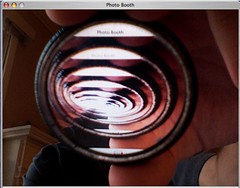
If your camera is like mine and stuck to your computer, the situation is not quite as straightforward. You can get feedback by holding up a little mirror in front of the lens and pointing it the screen, but it’s just not the same. In the photo to the left, I did just that, holding up a little round mirror in front of the iSight camera, pointing at the screen.
Quartz Composer
Quartz Composer (QC) is a graphical programming tool for programming graphics. It’s a surprisingly well-kept secret; it’s an incredible piece of easy to use software, and it’s part of the Xcode development environment that comes with Mac OS 10.4 Tiger. If you have a newer Mac that came with 10.4 preinstalled, or if you did not install Xcode when you installed 10.4, you may have to run the Xcode install program on the install DVD. If you have a recent vintage Mac and do not have 10.4, this just might be a good reason to upgrade.
This is not, by any means, the only tutorial on getting started in QC; you may also want to look at the RSS screen saver tutorial on engadget and/or the Quartz Composer Programming guide.
Let’s get started.
If you have the developer tools installed, you can find QC at
(hard drive)>Developer>Applications>Graphics Tools>Quartz Composer. Open it up. You will be greeted by an “assistant” dialog box that would like you to choose a template. Since we want to start with a blank slate, click “Cancel.” (You may, later, want to see the examples that are given if you do start with one of the templates.) Make a new Quartz Composer file (a “Quartz Composition”) by selecting “New” from the file menu.
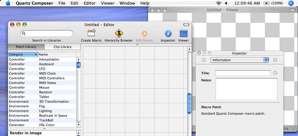
There are three main windows in QC, the Editor, the Inspector, and the Viewer. Happily, all three are labeled and do exactly what you’d expect. The Editor window is usually open. In it, you will find space (that looks like graph paper) for laying out your programs, and a couple of tabbed columns. Using buttons in the upper right corner of the Editor, you can also show or hide the Inspector and Viewer windows. The Inspector lets you see and change parameters of the different functions, and the Viewer window shows you a real-time video preview of your composition.
In the editor window, select the “Patch Library” tab above the column list on the left side of the window. The library consists of a neatly organized list of different routines, called “Patches,” that you may want to include in your composition. The first patch that we want to add is Billboard, a simple renderer (drawing) routine that just sends its output to the screen (the Viewer window, in this case). To add this patch, scroll down the list until you find the renderer called “Billboard,” and double click on it. When you do so, the Billboard routine shows up as a rounded box in the layout area of the Editor window. You can select it (by clicking on it) and view its properties by looking in the Inspector window.
On its own, the Billboard patch doesn’t really do anything; it doesn’t have any input to display. Let’s give it some input. If you have an iSight camera, find the patch in the Generator category called “Video Input,” and add it by double-clicking as before. (If you don’t have a video camera, you can still play along: use the patch “Plasma Image” in its place, at least until you know what you’re doing otherwise. The 20 kB ZIP archive that accompanies this tutorial includes examples that do and do not require a video camera.) Unless you’ve moved anything, the Video Input patch that you just added is a little rounded box sitting on top of the “Billboard” routine. Drag the Video Input box to the left of the Billboard box, so that you can see both.

Here’s the trick: The little boxes that represent patches have lists of little circles on their left or right sides (or both). These are terminals, where you can wire up inputs and outputs. Data generally flows left to right; connectors on the left side are inputs to a patch, and connectors on the right are outputs. You can make a connection between two points by dragging to create a line from an output to an input. Go ahead and try: Wire up the “Image” output (of “Video Input”) to the “Image” input (of “Billboard”). The wires are a little bit like wet spaghetti; it’s a clever implementation. Open up the Viewer window if it isn’t already open. It should display the video input signal that you’re feeding it.
Congratulations: you’ve just made a working Quartz Composer program, the real-time-video equivalent of hello, world. That’s the hard part, everything else is just icing on the cake.
The video thus far only fills a portion of the Viewer window. To fix that, highlight (select) “Billboard” by clicking on it. Open the Inspector (by clicking on its toolbar icon) if it is not already open. Use the pop-up menu at the top of the Inspector window to choose the “Input Parameters” panel. This panel lets you enter fixed parameters for inputs to a pat that are not wired up externally. (If values are wired to the inputs, you can view, but not change, the values of the inputs in this panel.) Right now, we want to change the value of the “Width” parameter, that controls how wide the final image is. The default value is 1, you should change it to 2, since the rendering destination is defined to be two units wide. (Aside: Under the “Settings” panel of the Inspector, you may also wish to check the option “Enable Direct Core Image Rendering,” which can help to make video feedback more realistic.) Close the Inspector and verify that the image now fills the Viewer window.
Building a feedback loop
We’ve got the basics down, so let’s start moving towards getting video feedback. Begin by disconnecting the wire that we made earlier between “Video Input” and “Billboard.” You can do this by dragging the wire away from the input on the “Billboard” patch.
We also going to need a few more patches. The most important of them is “Core Image Accumulator,” which provides the frame-to-frame memory for the video feedback. We’re also going to need “Affine Transform” and “Source Over.” The Affine Transform will let us resize the video image and move it around on the screen. The Source Over patch will let us stack the new video frame on top of the old one in order to create the visual effect of the feedback. You can use the search box in the upper left corner of the Editor to help find items in the Patch Library. Arrange the patches as follows, left to right: Video Input, Affine Transform, Source Over, Core Image Accumulator, and Billboard. Each neighboring pair has an image output and input; wire them up. It should look like this:

There’s one more patch that we need to add right now: a second copy of the “Affine Transform” patch. You can get the second copy by using copy and paste as usual, or by placing a new copy from the Patch Library column on the left hand of the editor window. Place it below the “Source Over” and “Core Image Accumulator” patches.
To hook it up, drag a second wire from the “Image” output of the Core Image Accumulator to the “Image” input (i.e., the “Image” connector on the left side) of the new copy of Affine Transform. (While you can attach more than one wire to an output of a patch, remember that only one wire can be connected to a given input.) To complete the feedback loop, drag a new wire from the “Image” output of the lower Affine Transform patch to the “Background Image” input on the “Source Over” patch.
That’s a mouthful, so just take a look at the picture:

The feedback loop is both literally visible as a loop and is also a loop in the sense of computer programming. Every time that a frame of video is drawn, the loop is executed one time. The new frame of video input, after being resized in “Affine Transform,” will be stacked on top of the last frame of video in the “Source Over” patch. The Core Image Accumulator will store that frame of video until the next frame begins, where it provides an output to the second copy of “Affine Transform”, which will resize the old frame of video before it is combined with the new one in “Source Over,” and so on.
Setting Parameters
We’ve discussed resizing and moving an image with the “Affine Transform” patch. That’s what the patch is for, and since both copies are wired up, all we need to do is set the input parameters. Let’s begin with the first copy, the one on the upper left. Select the patch by clicking on it and then open the Inspector if it isn’t already open. As earlier, use the pop-up menu to get to the “Input Parameters” panel in the Inspector. Change the settings for both Scaling X and Scaling Y to 0.2. On the other copy of “Affine Transform,” set both scalings to 1.1. In the first case, we’re scaling down the input image (to 20 percent of the original) so that it takes much less than the whole screen, thus leaving room to see the feedback graphics. In the second case, we’re enlarging the “old” image, by ten percent in every frame. You can play with both of these values to see what the effects are.
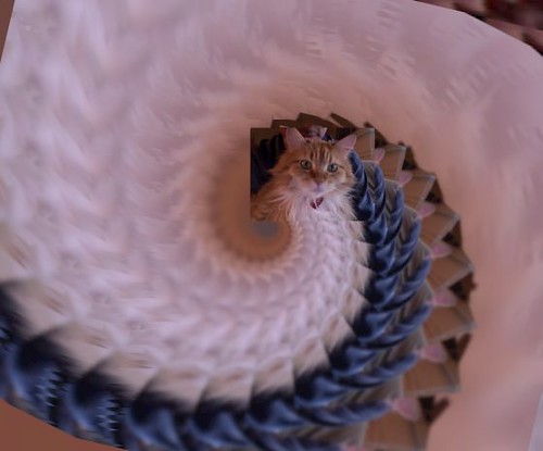
That’s it for settings, so take a look in the Viewer window to see how it works. Your image should look something like this (your cat may vary):

Clearly we’ve managed to produce video feedback, but it would be nicer if the live video signal weren’t stuck in the corner. In order to center the video image on the screen, we’ll use a couple of other patches that can tell us where the center of the screen is. This is an excellent opportunity to introduce the use of Macros in Quartz Composer, which are essentially subroutines that you can build on your own.
Building Macros
To create a macro, click the big button in the top center of the Editor window that says “Create Macro.” (Sometimes it just makes sense, doesn’t it?) That produces a brand-spanking-new patch, labeled “Macro Patch,” that you can edit. To edit a macro patch, double-click on it. To stop editing the macro and exit back to the main program, click the “Edit Parent” button in the top center of the Editor window. You can always open up the macro for editing later if need be.
We want our new macro to tell us where the center of the screen is. If you haven’t yet created the new macro patch, go ahead and do so, and then double-click on it so that we can edit its contents. From the Patch Library column on the left side of the screen, add two patches: “Rendering Destination Dimensions” and “Math.”
The “Rendering Destination Dimensions” patch outputs (among other things) the pixel width and height of whatever viewing window is being used. We want to take those two numbers, divide them by two to find the center in each direction, and then output the two results.
Click on the “Math” patch and open the Inspector to edit its properties. In the Settings panel of the Inspector, Click the “-” (minus) button where it says “Number of operations,” since we’ll only be using the panel for a single operation (division by two). Then go to the “Input Parameters” panel of the Inspector and change Operation #1 to Divide, and Operand #1 to 2. Those settings mean that the Math patch will take whatever shows up at the Initial Value input and divide it by two. Back in the editor window, duplicate the Math patch. You can do this by copying and pasting, selecting Duplicate (command-d) from the edit menu, or by option-shift dragging the Math patch itself. By duplicating the patch, you make another copy that has the same input parameters as the original, which would not be the case if you got a new copy from the Patch Library.
Let’s wire up the macro. Drag a wire from the “Pixels Wide” output of “Rendering Destination Dimensions” to the “Initial Value” input of one of the Math patches. Now pop-up a contextual menu on that Math patch by holding down the ctrl (control) key while clicking on that same copy of the Math patch. From that menu, select Published Outputs>Resulting Value. By doing this, you indicate that the output of this math function (the “Resulting Value”) should be “published,” which (in this case) means sent as an output of the whole macro function. A published input or output is indicated on the function by a colored circle at the terminal. After you’ve selected the menu option, you are given a chance to name that output value signal. Name it “Xout.” Repeat this procedure for the other axis, connecting “Pixels High” to the “Initial Value” input of the other Math function. Again, publish the resulting value and name it. Creatively, I named mine “Yout.” The completed contents of the macro patch should look like this:

Click on “Edit Parent” to get back to the main program. The new macro patch is still labeled “Macro Patch,” but we can change that. Click the patch to select it and then open the “Information” panel of the Inspector. Here, you can enter a new title for the patch. I called mine “Find Screen Center,” but you can name yours JellyBean (after my cat). Drag your new patch to sit on the left side of the editor window, below the “Video Input” patch. Drag two new wires, connecting the Xout and Yout outputs of your patch to the “Origin X” and “Origin Y” inputs, respectively, of one of the two “Affine Transform” patches. Then repeat, dragging two more wires from the outputs of your patch to the respective Origin inputs of the other “Affine Transform” patch.
Bob is your uncle.
Yup, stick a fork in yourself, you’re done. Open up the Viewer window and check it out. As you resize the window, the macro patch that you built still determines where the center is, and keeps your image centered on the screen. I saved this version as Feedback1.qtz, and it’s included in the 20 kB ZIP archive that accompanies this tutorial. At this stage, it’s good enough to deploy, but there are still a few more nice touches we can add to the program.
If you’ve had enough and want to skip right to using it, scroll down to the section below labeled, “Using Quartz animations as screen savers.” Otherwise, we’ll look at some easy but significant improvements that we can make to the program.
Extra icing on the cake
One of the charming things about “real” video feedback is that little misalignments in the camera twist and turn and move the image around, making wacky fractal spirals and things. A quick hack to the program can produce a similar effect. Add the patch “Random” to your program, and wire its output to the “Rotation” input of the lower copy of “Affine Transform,” the one that is in the feedback loop. Select the Random patch and open up the Inspector. In the Settings panel of the Inspector, move the Variability slider to the lowest non-zero number possible. I can get mine to 0.003. This parameter controls how quickly the output value changes. Switch to the “Input Parameters” panel of the Inspector, and set the minimum and maximum values to -25 and 25, respectively. That’s it for this revision, which is saved as Feedback2.qtz in the ZIP archive. Check the Viewer to see how it looks:
We can make a couple of other incremental improvements by adding other random variations. First, wire the output of the existing Random patch to the Rotation input of the other copy of “Affine Transform.” That will make the central image rotate in sync with the background. Now add a second Random Patch. Set its Min & Max to 1 and 1.5, respectively. Change its variability to some other low, non-zero number. (The variability parameter acts as a the seed for the random number generator; if you have two Random patches with the same value, they will vary in sync.) Wire the output of this Random patch to both of the Scaling inputs of the lower “Affine Transform” patch. This will slowly vary the scaling of the video feedback. Check the Viewer to see how it looks. This version is saved as Feedback3.qtz in the ZIP archive.
Using Quartz animations as screen savers
You can use Quartz .qtz files in a number of ways. The original intention of Apple was that you use them as elements in programs that you write. But, among other things, you can also preview them directly in the finder, view them in the Quicktime Player, or use them as screen savers. To use one as a screen saver, just put it in your screen saver directory. That’s in (your home folder)>Library>Screen Savers>. You can also put in the system-level library directory, in (hard drive)>Library>Screen Savers. To choose a screen saver for use, select it in the “Desktop & Screen Saver” pane of System Preferences. If you haven’t followed along closely enough to build your own screen savers, you can still try out the versions in the ZIP archive as screen savers.
Where to go from here
There are limitless possibilities for graphical programming in Quartz Composer. Look through the Patch Library at the variety of different built in patches. Many of them are the same fun-house filters that show up in Photo Booth; you could start by inserting them into this program. One variation that I particularly like is to use the “Bloom” patch between “Source Over” and “Core Image Accumulator.” But why stop with little variations? Start with a new signal input, such as audio input on your hard drive. Try using some of the other built in simulations, like the “Particle System” renderer, which can produce a remarkable variety of effects with small changes in the input parameters. Above all, look at the examples that came with the program. They’re located in the directory Developer>Examples>Quartz Composer. A couple of my favorite are SuperBalls and Mouse Tracking. These provide a couple of hints about how you might start making interactive artwork with Quartz Composer.
Good luck and have fun!
heh, I also use my cat in my video/computer experiments….
(thanks for the qtz tutorial)
-anony mouse
is the affine transform patch unique to QC 4.0?? doesn’t seem to appear in 3.1 :(
Apparently, it’s been renamed to "Image Transform."
Windell H. Oskay
drwho(at)evilmadscientist.com
http://www.evilmadscientist.com/
tyvm!