Tag Archives: electronics

Mailbag: Hacking a Mega-Peggy

grayscale

Tony writes in with a question about hacking our DIY LED matrix kits:

“I’m building a Peggy 2LE. I have completed the wiring with the exception of the LEDs. I have constructed an external frame which has 600 mounting points for my LEDs using a Matrix design of wires crossing every 3 inches. Since the Peggy 2LE has 625 LEDs I need to know how I can drive the 30 anode connections and 20 cathode connections to the wiring them to the Peggy 2. Or am I going to have to wire each LED to the PCB of the Peggy + and – LED locations?”

And, that’s actually an interesting topic.  We’ve written before (here and here) about some giant-scale variations and modifications to our Peggy 2 and Peggy 2LE LED matrix kits, but we haven’t really addressed how one might go about building it.

First off, since you asked— and though we recommend against it —it is indeed possible to build an off-board LED matrix by simply running individual running wires from every LED location on the Peggy circuit board to every LED.  There are 625 LEDs in a 25 × 25 grid, and if each has two wires… that turns out to be quite a few wires.

MakerFaire2011 - 144

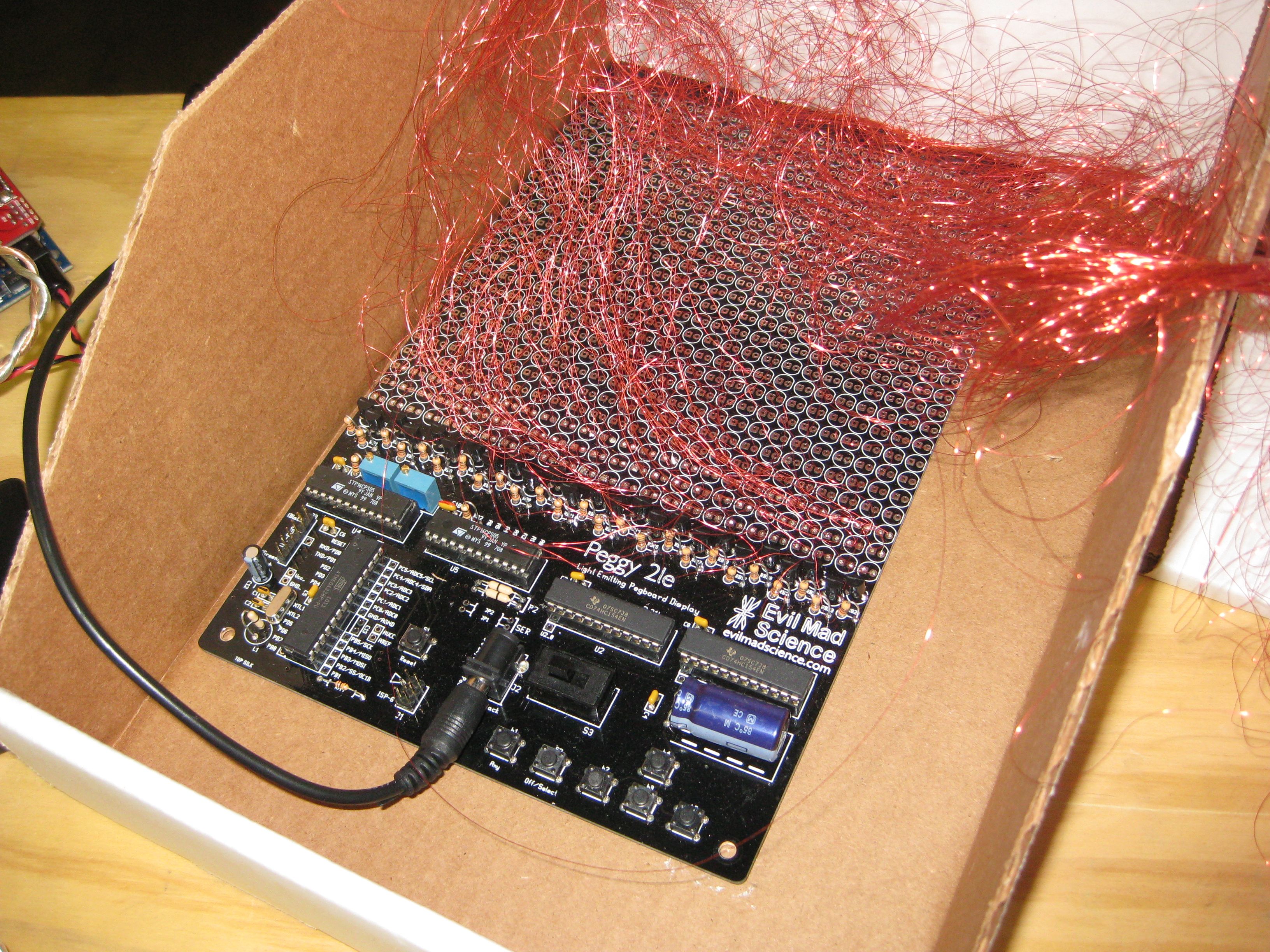
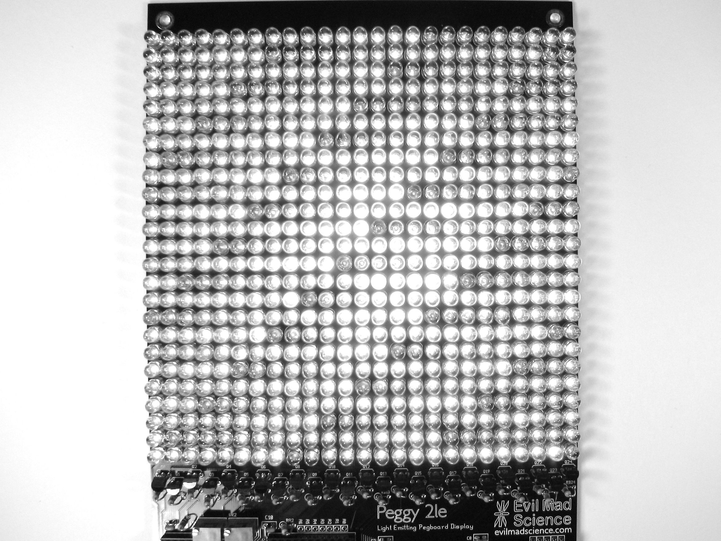
While *ahem* labor intensive, this method does work. We know this partly because several people have actually done it.  The “rats nest” of thin, red-lacquered magnet wire shown above is one example, and the Peggy shown here is another victim example of this method.

Fortunately, very fortunately, there are easier ways: think 50 wires, rather than 1250. And, there are a few other clever tricks that you might want to consider when changing the size of the matrix.  For example, it’s possible to use the Peggy 2LE to drive an off-board LED matrix of size up to 25 × 32 without adding any other extra hardware.

Continue reading Mailbag: Hacking a Mega-Peggy

Basics: Picking Resistors for LEDs

5 mm warm white diffused LED

So… you just want to light up an LED. What resistor should you use?

Maybe you know the answer, or maybe everyone already assumes that you should know how to get to the answer.  And in any case, it’s a question that tends to generate more questions before you actually can get an answer: What kind of LED are you using? What power supply? Battery? Plug-in? Part of a larger circuit? Series? Parallel?

Playing with LEDs is supposed to be fun, and figuring out the answers to these questions is actually part of the fun.  There’s a simple formula that you use for figuring it out, Ohm’s Law. That formula is V = I × R, where V is the voltage, I is the current, and R is the resistance. But how do you know what numbers to plug into that formula to get out the right resistor value?

Continue reading Basics: Picking Resistors for LEDs

Basics: Blink an LED with an AVR

AVR Blink Blog Post

Getting an AVR to blink might seem like an incredibly difficult task compared to the usual Arduino blink, but it really isn’t! In this post we will be uploading a basic blink example to an ATtiny2313. This is perfect for projects where using an Arduino would be over the top. So let’s get started!

Continue reading Basics: Blink an LED with an AVR

Basics: Open Collector Outputs

SN7407N

One of the joys of working with basic digital electronics– and logic gate ICs in particular –is that it almost works like building with a set of Lego blocks: One output goes here, which connects to the next input here, and so forth until it does what you wanted.

If you’ve played with chips like these, you’ve probably also come across chips with “open collector” outputs. And if not, they’re worth knowing about. Open-collector outputs form the basis of a number of clever tricks for level-shifting and interfacing between different types of logic, and from logic to other types of electronic circuits.

In what follows, we’ll work with the SN7407N, which is one of the most basic ICs with open-collector outputs. We’ll discuss what it means to have “open collector” outputs, and show some of the different ways that they are used. Continue reading Basics: Open Collector Outputs

Basics: Power dissipation and electronic components

Lovely Resistors


An ever-present challenge in electronic circuit design is selecting suitable components that not only perform their intended task but also will survive under foreseeable operating conditions. A big part of that process is making sure that your components will stay within their safe operating limits in terms of current, voltage, and power. Of those three, the “power” portion is often the most difficult (for both newcomers and experts) because the safe operating area can depend so strongly on the particulars of the situation.

In what follows, we’ll introduce some of the basic concepts of power dissipation in electronic components, with an eye towards understanding how to select components for simple circuits with power limitations in mind. Continue reading Basics: Power dissipation and electronic components

Basic kludges: 5 minute SOIC-DIP adapter

Socket Adapter - 5

So, you’re almost done building the new circuit board when suddenly…

Socket Adapter - 7

Doh! We’ve got the right chip handy, but only in the wrong package!

Socket Adapter - 6

No siree, that chip will not fit in our socket. :(

Socket Adapter - 2

Fortunately, we’ve got tools: some thin copper wire, a spare DIP socket, and a few minutes of time. So, even without a readymade SOIC-to-DIP adapter, we’re still good to go.

Socket Adapter - 4

It’s helpful to raise the little chip up a bit with a wood or plastic shim, and then to fix it in place with hot or super glue. Strip the insulation off of the wire, and cut into small sections. Starting at the center of the chip, insert one end of each little wire into the socket and solder the other end to the matching pin of the IC. Trim the leads just above the chip.

Socket Adapter - 8

And (poof!) it fits in the circuit board after all.

Beautiful? Heck no. (More like slimy but satisfying.) But finding a way to get your circuit board to light up without a few more days for the “right” chip to show up can be a wonderful thing indeed.

Octolively: Digital interactive LED surfaces

Octolively Array: 8 inches wide

Octolively is an all-new, open source interactive LED surface kit that we’re releasing today. Octolively features high resolution– an independent motion sensor for every LED, stand-alone operation, a variety of response functions, and easy scaling for large grids.

Warm white (left), Regular "cool" white (right)

Octolively represents our fourth generation of interactive LED surfaces.

Long-time readers might recall the original Interactive LED Dining Table, the infamous Interactive LED Coffee Tables, or the third-generation, not-very-creatively-named Interactive LED Panels. All of these surfaces were based on fully-analog circuitry with large circuit boards and a fairly high ratio of LEDs to sensors– typically 20:1.

Octolively: single unit, powered down-2

Octolively, by contrast, is based on smaller, lower-cost circuit board modules, “only” 4×8 inches in size. Part of the reason for this is so that there’s more flexibility in making arbitrarily shaped arrays. Arrays can now be as skinny as 4″ wide, or as wide as you like.

Each module features 8 LEDs and 8 independent proximity sensors– one for each and every LED. The LEDs are (huge) 10 mm types, and that chip in the middle of the board is an (also huge) ATmega164 microcontroller.
Each sensor consists of an infrared LED and phototransistor pair, which– together with polling and readout from the microcontroller –acts as reflective motion sensor. The LEDs are spaced on a 2-inch grid, and the edge connectors allow boards to be tiled seamlessly.

Because the circuit is now primarily digital, it’s easy to store a variety of response functions in the microcontroller. Our standard firmware contains 8 different response functions– fades, ripples, shadows and sparkles, which you can change with a button press. As it’s an open source project, we’ll expect that (in time), others will become available as well.

Octolively: 3x3 grid of boards

And, because the entire circuit is self-contained on the module, the surface scales effortlessly– you get very high resolution over huge areas without bandwidth bottlenecks, and no need for a central computer.

Of course, static pictures don’t do much justice for interactive LED surfaces. (We’ve embedded our video above. If you can’t see it here, click through to YouTube.)

Octolively, warm white LEDs

And doesn’t that look good with warm white LEDs?

Octolively begins shipping next week. Additional details– including the datasheet and documentation links –are available on the product page.