Over the course of the past few years, we’ve been writing occasional “Basics” articles, about introductory topics in electronics and microcontrollers. In the spirit of making things easy to find, we’ve now tagged them so that you can find them with this link, and we’re collecting them together in this index that will be updated from time to time.
Our “Basics” articles about electronics in general:
- Basics: Picking Resistors for LEDs
- Basics: Finding Pin 1
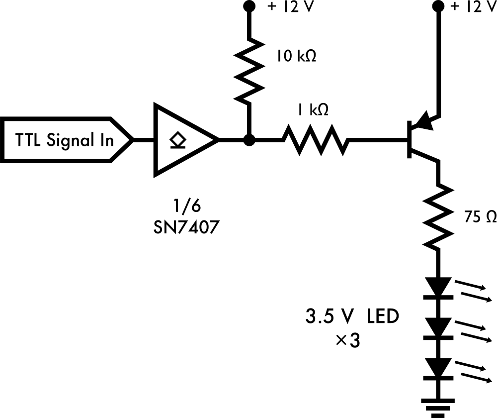
- Basics: Open Collector Outputs
- Basics: Simple LED Pumpkins
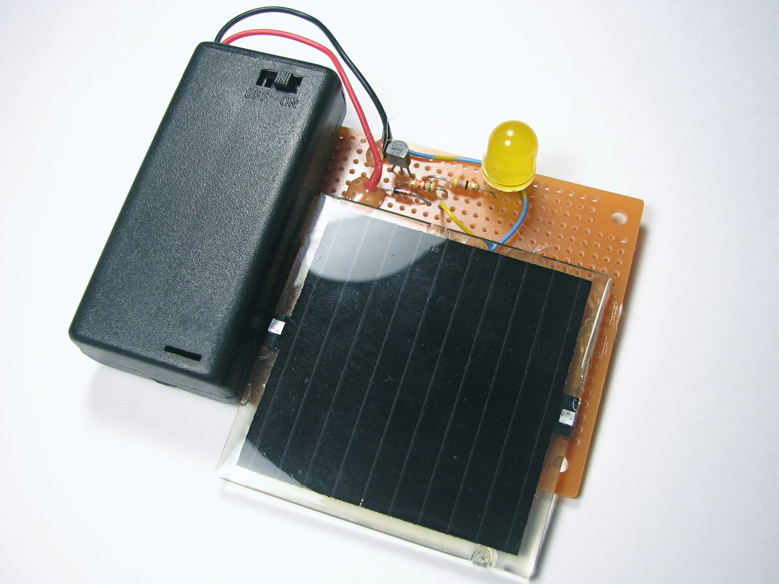
- Simple Solar Circuits
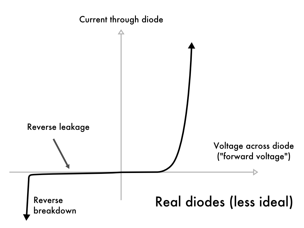
- Basics: Introduction to Zener Diodes
- Basics: Power Dissipation and Electronic Components
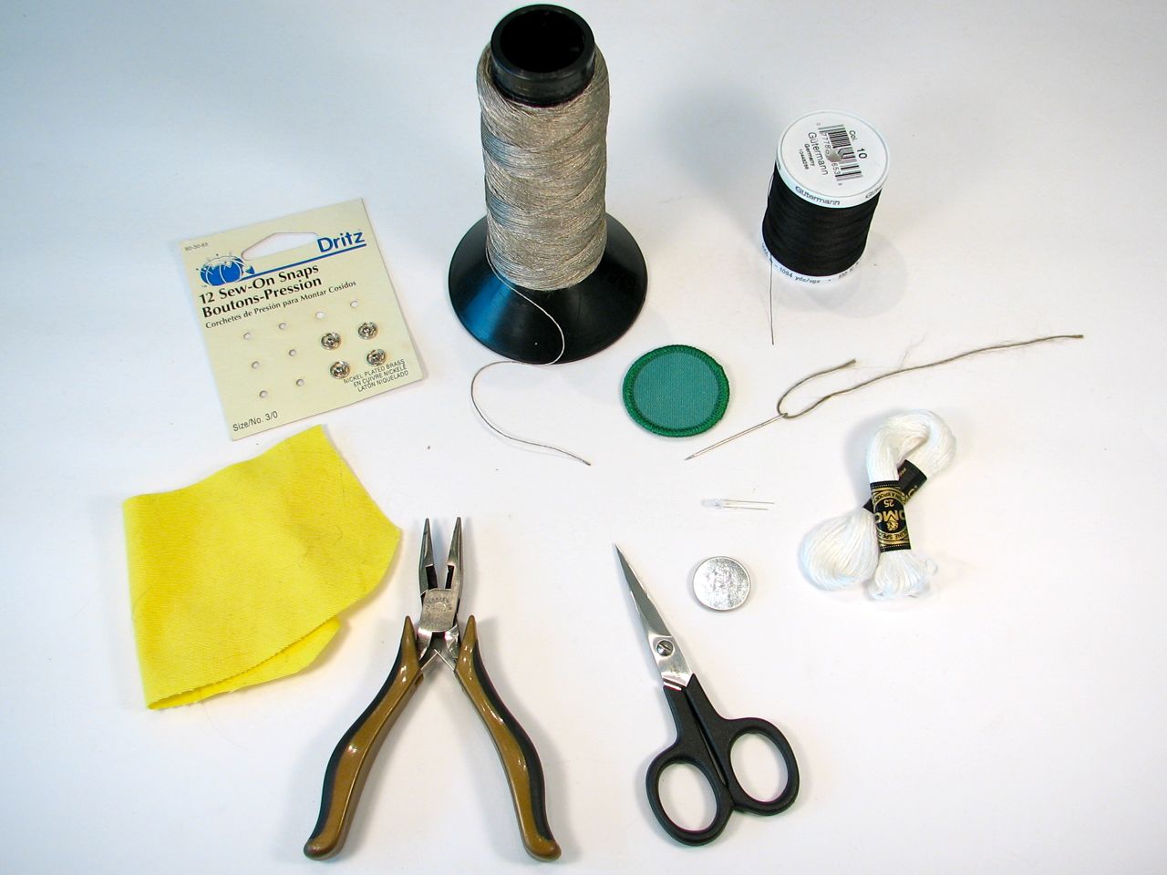
- Soft Circuit Merit Badge
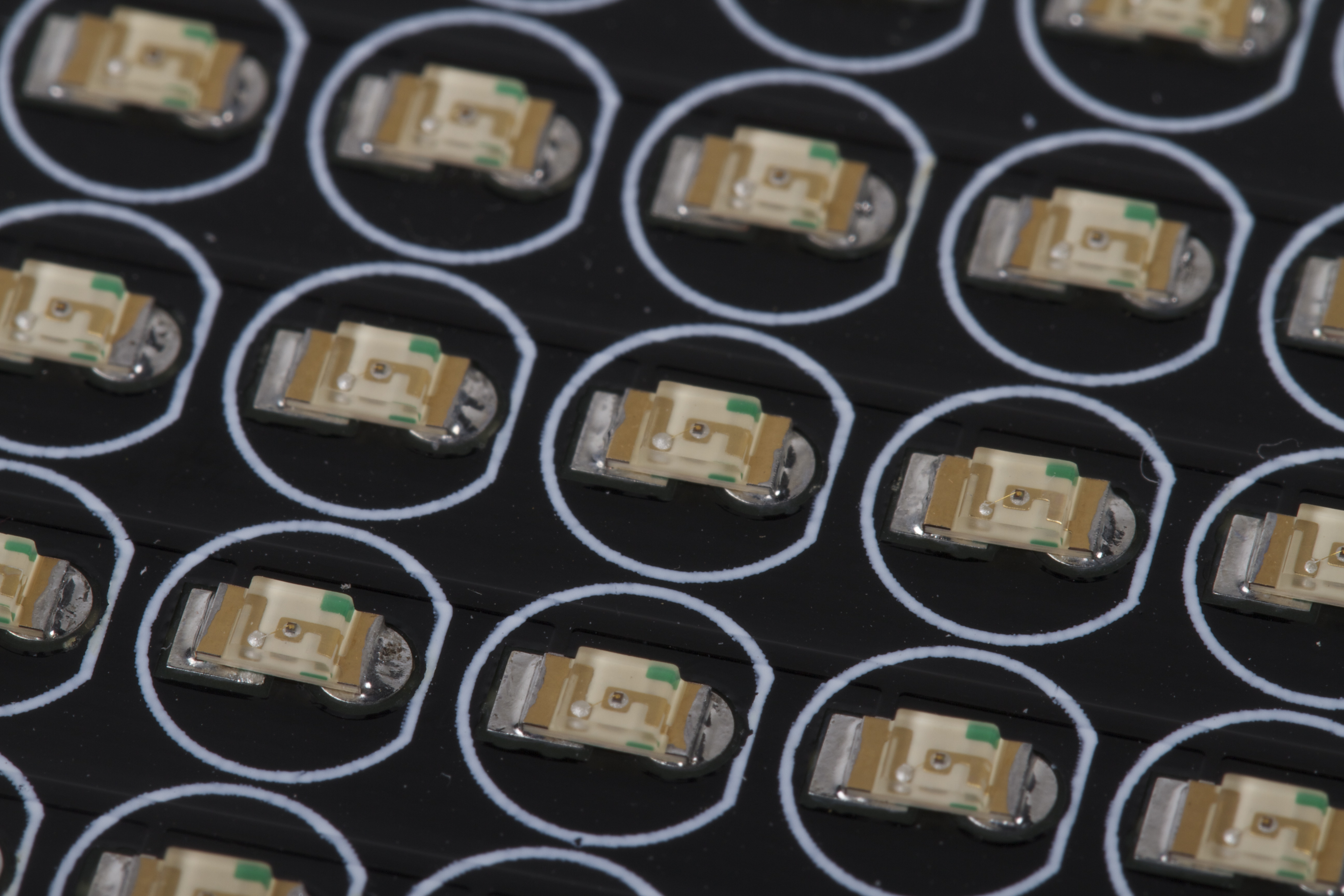
- Basics: Up Close and Personal with Solder Paste
- Five Electronics Tools You Might Not Know About and More Cool Electronics Tools
- Tricks of the trade: Twisting wire bundles
Additional “Basics” articles about working with AVR microcontrollers:
- Basics: Blink an LED with an AVR microcontroller
- Using AVR microcontrollers: Minimalist target boards
- Basics: Serial Communication with AVR Microcontrollers
- Basics: Using an Accelerometer with an AVR Microcontroller
- AVR Basics: Reading (and writing) flash contents
- Quick and Dirty D to A on the AVR: A timer tutorial
- Resources for getting started with AVRs


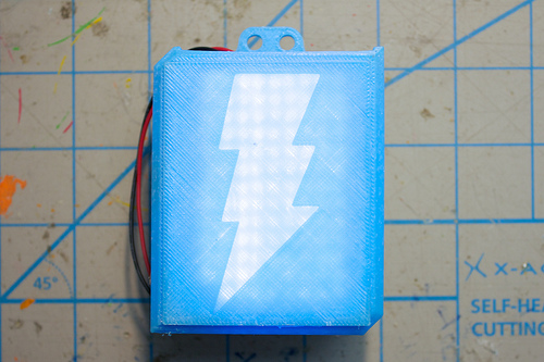
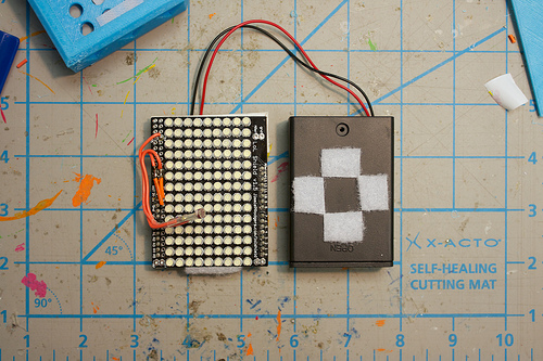


![?? [Senko] - Tokushima LED Art Festival](https://bcdn.evilmadscientist.com/media/2013/05/senkoflash2daylight.jpg)
![?? [Senko] - Tokushima LED Art Festival](https://bcdn.evilmadscientist.com/media/2013/05/senkoflash3dark.jpg)