


Here’s a simple problem: “How do you make an LED turn on when it gets dark?” You might call it the “nightlight problem,” but the same sort of question comes up in a lot of familiar situations– emergency lights, street lights, silly computer keyboard backlights, and the list goes on.
Solutions? Lots. The time-honored tradition is to use a circuit with a CdS photoresistor, sometimes called a photocell or LDR, for “light-dependent resistor.” (Circuit Example 1, Example 2.) Photoresistors are reliable and cost about $1 each, but are going away because they contain cadmium, a toxic heavy metal whose use is increasingly regulated. There are many other solutions as well. Look here for some op-amp based photodetector circuits with LED output, and check out some of the tricks used in well-designed solar garden lights, which include gems like using the solar cell itself as the sensor. (Our own solar circuit collection is here.)
In this article we show how to build a very simple– perhaps even the simplest– darkness-activated LED circuit. To our LED and battery we add just three components, which cost less than thirty cents altogether (and much less if you buy in bulk). You can build it in less than five minutes or less (much less with practice).
What can you do with such an inexpensive light-controlled LED circuit? Almost anything really. But, one fun application is to make LED throwies that turn themselves off in the daytime to save power. Throwies normally can last up to two weeks. Adding a light-level switch like this can significantly extend their lifetime.
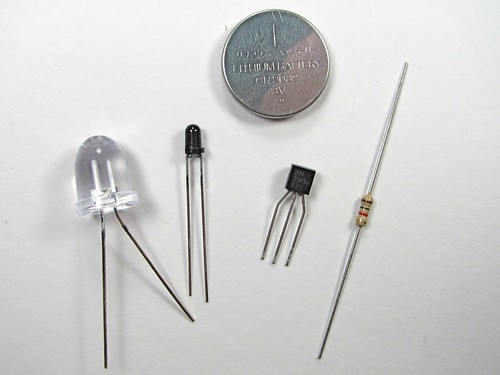
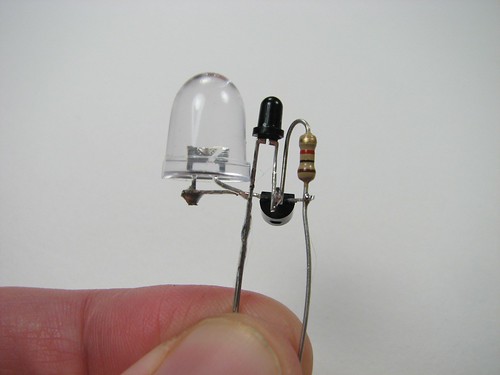
Here are our components: On top: a CR2032 lithium coin cell (3 V). On the bottom (L-R): the LED, an LTR-4206E phototransistor, a 2N3904 transistor, and a 1 k resistor.
This LED is red, blindingly bright at 60 candela, in a 10 mm package. It casts a visible beam, visible for about twenty feet in a well-lit room. We got the LEDs and batteries on eBay, and the other parts are from Digi-Key, but Mouser has them as well. As we mentioned, the last three cost about $0.30 all together, and much less in bulk.
The LTR-4206E is a phototransistor in a 3mm black package. The black package blocks visible light, so it is only sensitive to infrared light– it sees sunlight and incandescent lights, but not fluorescent or (most) discharge lamps– it really will come on at night.
Our starting point is the simplest LED circuit: that of the LED throwie, which has an LED driven directly from a 3V lithium coin cell. (Funny looking example
here.) From this, we add on the phototransistor, which senses the presence of light, and we use its output to control the transistor, which turns the LED on.
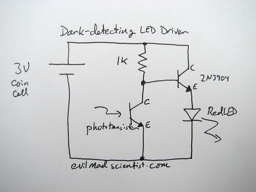
The circuit diagram looks like this; please ignore the messy handwriting. ;)
When light falls on the phototransistor, it begins to conduct up to about 1.5 mA, which pulls down the voltage at the lower side of the resistor by 1.5 V, turning off the transistor, which turns off the LED. When it’s dark, the transistor is able to conduct about 15 mA through the LED. So, the circuit uses only about 1/10 as much current while the LED is off. One thing to note about this circuit: We’re using a red LED. That’s because the voltage drop across the transistor allows less than the full 3 V across the LED. The full three volts is really only marginal for driving blue LEDs anyway, so two-point-something really doesn’t cut it. (Might be able to work around that with a cheap FET– haven’t tried yet.)
And now, let’s build it. You can certainly put this together on a breadboard, but there’s something more satisfying about the compact and deployable build that we walk through here.
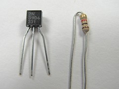
First get the transistor and the resistor. The pins of the 2N3904 are called (left-to-right) Emitter, Base, Collector, when viewing it from the front such that you can read the writing. We’re going to solder the resistor between the leads of the Base and Collector of the transistor. Unusual part: hold the resistor with its leads at 90 degrees to those of the transistor while you solder.
Stay safe when you do this: Use Mr. Hands.
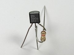
After soldering, clip off the excess resistor lead that is attached to the transistor base (middle pin), as well as the excess length of the collector pin.
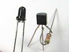
Next, we add the phototransistor. Note that it has a flatted side, much like an LED does. This pin on that side is the collector of the phototransistor. Solder the collector (flatted side) to the middle pin (the base) of the transistor, again at 90 degrees. The other pin of the phototransistor, the emitter, is left unconnected for the moment. (Here is an alternate view of what that should look like when you’re done.)
Finally, we need to add the LED. To do so, we need to know which side is the “positive,” or anode side of the device.
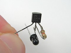
Regrettably markings of LEDs are not consistent, so the best way to be sure is to test it with the lithium coin cell– put the LED across the terminals of the cell and, when it lights up, note which side is touching the (+) terminal. (Usually, it’s the one with the longer lead.) Solder the “positive” lead of the LED to the emitter pin of the transistor– it’s the one on the left, which doesn’t have anything soldered to it. Trim away the excess lead of the LED that goes past the solder joint. Solder the other pin of the LED (the “negative” pin, or cathode) to the emitter of the phototransistor, the pin on the non-flatted side, which does not have anything connected to it yet.
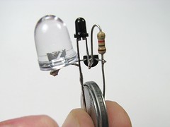
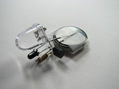
By this point, there are only two pins sticking down below the components: One that goes to the resistor and collector (rightmost pin) of the transistor, and one that goes to the emitter of the phototransistor and to the cathode of the LED.
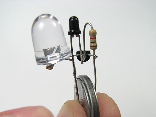
To test the circuit, squeeze the coin cell between these two terminals, positive side goes to the lead touching the resistor. You can’t see the LED on here because these photos were taken with incandescent lighting– it wouldn’t turn on.
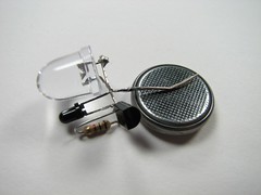
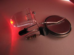
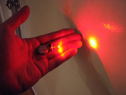
Bending the leads to contact the lithium cell a little more reliably, you can try it out a little more easily. In the photo on the right, I cupped my hand over the circuit– so the LED turned on.
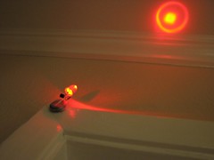
To make this into an actual “throwie,” you still need to add some tape and a magnet, but that’s quite easily done. This one makes a pretty good nightlight attached to the top of a doorframe– when the room lights are off, it shines a bright, bright spot on the ceiling.
Where to go from here? While this little circuit can do something on its own, it would probably also be happy as part of a larger circuit. At a minimum, note that if you work with batteries that have lower internal resistance than the lithium coin cells, you should place an appropriate resistor in series with the battery before trying to operate this circuit– or else you may put too much current through the LED. Certainly, this is one of the easiest and least expensive ways to control an LED with a photosensor. (Unlike, say, this method?) You could also consider crossing it with some more extreme mods, like the
Talkie Throwies that know Morse code, or for more extreme hackers, bagel throwies.
Note added, May 2012:
This set of components works well, and is a pretty neat little dark detector.
We have received hundreds of responses to this article both here in the comments (which are now closed due to abuse) and by e-mail, asking (a) how you would modify this circuit to do X, Y, or Z, (b) whether you can use component THX1138 for the phototransistor, because that’s the only one available on the tropical island where you live, or (c) why your circuit doesn’t work, because you only made two substitutions.
We are, for the most part,unable to respond to inquiries like these. Designing circuits is not always trivial, and we don’t want to give flippant (or worse, wrong) answers, when people are trying to solve problems.
To give the quick set of answers to some of the popular questions:
- This it is a special set of parts that is chosen to work well together, and several simplifications have been made on the basis of which particular components are used– for example, we rely on the internal resistance of the coin cell, so that we don’t need an external current-limiting resistor. Because of this, there aren’t many simple direct substitutions that work well.
- There are plenty of great CdS (“LDR”) phototransistor circuits out there. For better or worse, this is not one of them. (We happen to think betterfor a number of reasons.)
- You can’t just substitute a white (or UV, or blue, etc) LED directly, because there isn’t enough voltage to drive it well. (We did actually show how to do this one– see below.)
- You can’t just substitute 12 V, because the current will be too high, and will blow out your LED. Yes, there are ways to do it, but you have to think it through.
- Some other phototransistors will work, and some will not. If you would like to know which, you can compare their datasheets, or– better yet –just try it!
If you would like to see a couple of other examples of dark-detecting circuits, please see here:
A dark detecting circuit for your pumpkin and a forum post showing how to build this circuit with white LEDs.

Hey there,
I am in the process of developing a 8′ x 8′ light sensitive LED wall that as a person passes by the wall, wherever their shadow casts, the LED’s will come in creating a live action "light shadow". I found all the parts you used with the exception of a IR light source. Long story short, what would you recommend as a IR light source as I will be inside in a closed gallery space where sunlight will not affect the array.
Thanks,
Brian
…and I just reread the section on the fact the LTR can see incandescent light also. So with that in mind, should I just go and pick up a couple incandescent bulbs and call it good versus trying to track down some more costly IR bulbs?
~ Brian
Infrared LED illumination panels might be a good choice, too.
Windell H. Oskay
drwho(at)evilmadscientist.com
http://www.evilmadscientist.com/
Do you have an recommendations on where to find an IR LED panel that would be large enough to cover an 8′ x 8′ wall (without costing an arm and a leg, if possible)?
Great helpful photo descriptions here. Which led’s are the best quality ?any particular make?
Please help me.. Can I use this circuit to supply a 9V supply required circuit?
Or else, What are the required values of these components to give supply to the 3-9V decorative LED light circuit?
Pls help me.. I want to use this as switch to this circuit shown in <a href="http://www.electronicsforu.com/electronicsforu/lab/ad.asp?url=/EFYLinux/circuit/December2007/CI-01_Dec07.pdf&title=LED%20Lighting%20for%20Christmas">here</a>
http://www.electronicsforu.com/electronicsforu/lab/ad.asp?url=/EFYLinux/circuit/December2007/CI-01_Dec07.pdf&title=LED%20Lighting%20for%20Christmas
Thank you in advance
Hey i didn’t found a LTR-4206E phototransistor
Does any of you know a good substitute to this phototransistor
and I also have a question do all phototransistor detect light?
cause i have a phototransistor here but not the LTR-4206E phototransistor
i will be really glad if you answer my questions
windell, thanks for this tutorial – it’s very insightful. i have two questions:
– how long does the battery last in your example?
– is it possible to add an on/off switch? for example, the switch in position ‘A’ turns the light off (regardless of the light conditions), position ‘B’ turns the light on (regardless of the light conditions), and position ‘C’ does what you explained (LED is turned on by darkness and off by light).
thanks!
>how long does the battery last in your example?
About twice as long as it would without the detector– likely a week or more.
> is it possible to add an on/off switch? for example, the switch in position ‘A’ turns the light off (regardless of the light conditions), position ‘B’ turns the light on (regardless of the light conditions), and position ‘C’ does what you explained (LED is turned on by darkness and off by light).
Sure, use a DPDT switch, and short-circuit the light on in the "C" position, and disconnect it in the A position.
Windell H. Oskay
drwho(at)evilmadscientist.com
http://www.evilmadscientist.com/
hi wendell. thanks for the quick reply. i am a newby to this whole thing. would you be willing to put the entire circuit together? i will pay for whatever labor/parts. if i can see how it’s constructed, i’ll have something to study.
thanks!
Hello! Can i use ldr instead of phototransistor?
No, these are not the same thing at all.
Windell H. Oskay
drwho(at)evilmadscientist.com
http://www.evilmadscientist.com/
Can this be done with a PNP Transistor. Also i have an led light strip that runs off 9 – 12v. How could i use this as the load?
Thanks!
I have a cheep analog clock from Dollar store so I decided to put some LEDs in it i used your schematic to run it thank you loads, I got stumped on trying to get my photoresistor to turn the, light off the way i had it it would turn on the light when it seen light. Now I’m running it with a nine volt battery and changed up the resistors to work with the higher power source going to add more LEDs to produce more light, by the time I’m done it should look really neat i have to add another photoresister to it or find a new home for it so that it will stay off during the day may see if i can find a little solar panel for it so it can charge the battery when the LEDs are not running.
thanks
Anthony
p.s. here is a pic of it
http://i1134.photobucket.com/albums/m620/awjuhl/0116121430.jpg
well can someone suggest meh another alternative phototransistor that will work
I think the coin battery has about 200mah, does that mean 2 D batteries in a series will have about 2600 mahs. Does this mean the LED will last 13 times longer? I’m trying to make a night light for under a little box, not really a electronic guy —-wood stuff is my game. Thank You in Advance, Ken
This will not work as-is with D cells substituted; you’ll need to add a current-limiting resistor.
Windell H. Oskay
drwho(at)evilmadscientist.com
http://www.evilmadscientist.com/
You’re using and NPN transister there right? how can you do it with a PNP?
thanks
Hello EMSL!
I built this circuit with LED flicker bulb (and current limiting resistor) and 2 X AA batteries to have safe "candles" in windows over holidays at the house here. I was going to go the LDR route, but I liked the increased simplicity of the phototransistor circuit. Here’s the problem…once the phototransistor shuts off the circuit during the day, for some reason it doesn’t allow the circuit to come back on at night. I have to disconnect the battery and then the LED is on again until daylight. Any thoughts?
Thanks!
John
Nope, not sure. Someone else has reported this as well. It deserves research!
Windell H. Oskay
drwho(at)evilmadscientist.com
http://www.evilmadscientist.com/
I don’t know about Evil Mad Scientist, having read down the list of Posts
I think you have the patience of a Saint.
If people can’t get a simple Dark detecting circuit like this to work, they
should give up electronics and take up Bungee jumping with thin string
You are right, this was a 15 minute project using a breadboard.
I think the problem is related to the variable current draw from the 10mm flicker LEDs. When I swap a regular LED of similar general specs it works fine. I suspect a resistor across the LED to provide a base amount of current flow will hold the transistor properly…Does that make any sense at all?
And I don’t bungee jump.
j
how would i be able to manipulate this circuit to power a 60W incandescent bulb
Replace the LED with a solid-state relay that has LED input.
Windell H. Oskay
drwho(at)evilmadscientist.com
http://www.evilmadscientist.com/
Hi there,
I am a student from Nepal and I came to see your post. Which is very nice.
I couldn’t find LTR 4206E phototransistor in my area. So is there any substitute for that or may be LDR(i really don’t know). Please help me out. Thanks.
Thank you sir. It worked well…..
Nice one.
I tried building it , but didn;t found the photo diode in the market searched a lot but could’nt find it.
Finally I found one in a onld DVD circuit i used it and worked great.
I also found another simple circuit online , it used LDR instead of photo diode.
I found the LDR in market and build that one also.
the next one using LDR is: photo detector circuit
I built the circuit using a 3/8" LDR and a PN2222A transistor and it works great. I integrated the circuit into a solar lighthouse project I am building.
You can substitute the photo transistor with an LDR.
I wouldn’t vouch for that.
Windell H. Oskay
drwho(at)evilmadscientist.com
http://www.evilmadscientist.com/
Well, that’s an interesting coincidence then– it’s not designed to work that way.
Windell H. Oskay
drwho(at)evilmadscientist.com
http://www.evilmadscientist.com/