


Here’s a simple problem: “How do you make an LED turn on when it gets dark?” You might call it the “nightlight problem,” but the same sort of question comes up in a lot of familiar situations– emergency lights, street lights, silly computer keyboard backlights, and the list goes on.
Solutions? Lots. The time-honored tradition is to use a circuit with a CdS photoresistor, sometimes called a photocell or LDR, for “light-dependent resistor.” (Circuit Example 1, Example 2.) Photoresistors are reliable and cost about $1 each, but are going away because they contain cadmium, a toxic heavy metal whose use is increasingly regulated. There are many other solutions as well. Look here for some op-amp based photodetector circuits with LED output, and check out some of the tricks used in well-designed solar garden lights, which include gems like using the solar cell itself as the sensor. (Our own solar circuit collection is here.)
In this article we show how to build a very simple– perhaps even the simplest– darkness-activated LED circuit. To our LED and battery we add just three components, which cost less than thirty cents altogether (and much less if you buy in bulk). You can build it in less than five minutes or less (much less with practice).
What can you do with such an inexpensive light-controlled LED circuit? Almost anything really. But, one fun application is to make LED throwies that turn themselves off in the daytime to save power. Throwies normally can last up to two weeks. Adding a light-level switch like this can significantly extend their lifetime.
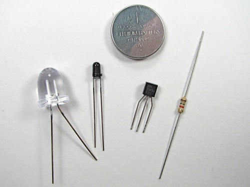
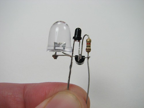
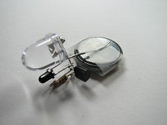
Here are our components: On top: a CR2032 lithium coin cell (3 V). On the bottom (L-R): the LED, an LTR-4206E phototransistor, a 2N3904 transistor, and a 1 k resistor.
This LED is red, blindingly bright at 60 candela, in a 10 mm package. It casts a visible beam, visible for about twenty feet in a well-lit room. We got the LEDs and batteries on eBay, and the other parts are from Digi-Key, but Mouser has them as well. As we mentioned, the last three cost about $0.30 all together, and much less in bulk.
The LTR-4206E is a phototransistor in a 3mm black package. The black package blocks visible light, so it is only sensitive to infrared light– it sees sunlight and incandescent lights, but not fluorescent or (most) discharge lamps– it really will come on at night.
Our starting point is the simplest LED circuit: that of the LED throwie, which has an LED driven directly from a 3V lithium coin cell. (Funny looking example
here.) From this, we add on the phototransistor, which senses the presence of light, and we use its output to control the transistor, which turns the LED on.
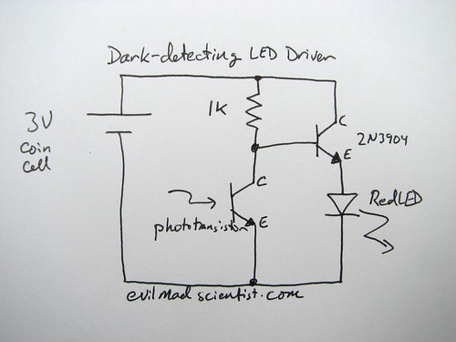
The circuit diagram looks like this; please ignore the messy handwriting. ;)
When light falls on the phototransistor, it begins to conduct up to about 1.5 mA, which pulls down the voltage at the lower side of the resistor by 1.5 V, turning off the transistor, which turns off the LED. When it’s dark, the transistor is able to conduct about 15 mA through the LED. So, the circuit uses only about 1/10 as much current while the LED is off. One thing to note about this circuit: We’re using a red LED. That’s because the voltage drop across the transistor allows less than the full 3 V across the LED. The full three volts is really only marginal for driving blue LEDs anyway, so two-point-something really doesn’t cut it. (Might be able to work around that with a cheap FET– haven’t tried yet.)
And now, let’s build it. You can certainly put this together on a breadboard, but there’s something more satisfying about the compact and deployable build that we walk through here.
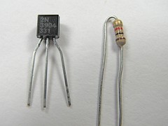
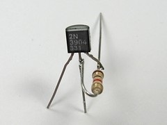
First get the transistor and the resistor. The pins of the 2N3904 are called (left-to-right) Emitter, Base, Collector, when viewing it from the front such that you can read the writing. We’re going to solder the resistor between the leads of the Base and Collector of the transistor. Unusual part: hold the resistor with its leads at 90 degrees to those of the transistor while you solder.
Stay safe when you do this: Use Mr. Hands.
After soldering, clip off the excess resistor lead that is attached to the transistor base (middle pin), as well as the excess length of the collector pin.
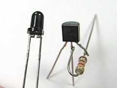
Next, we add the phototransistor. Note that it has a flatted side, much like an LED does. This pin on that side is the collector of the phototransistor. Solder the collector (flatted side) to the middle pin (the base) of the transistor, again at 90 degrees. The other pin of the phototransistor, the emitter, is left unconnected for the moment. (Here is an alternate view of what that should look like when you’re done.)
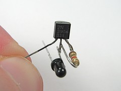
Finally, we need to add the LED. To do so, we need to know which side is the “positive,” or anode side of the device.
Regrettably markings of LEDs are not consistent, so the best way to be sure is to test it with the lithium coin cell– put the LED across the terminals of the cell and, when it lights up, note which side is touching the (+) terminal. (Usually, it’s the one with the longer lead.) Solder the “positive” lead of the LED to the emitter pin of the transistor– it’s the one on the left, which doesn’t have anything soldered to it. Trim away the excess lead of the LED that goes past the solder joint. Solder the other pin of the LED (the “negative” pin, or cathode) to the emitter of the phototransistor, the pin on the non-flatted side, which does not have anything connected to it yet.
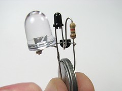
By this point, there are only two pins sticking down below the components: One that goes to the resistor and collector (rightmost pin) of the transistor, and one that goes to the emitter of the phototransistor and to the cathode of the LED.
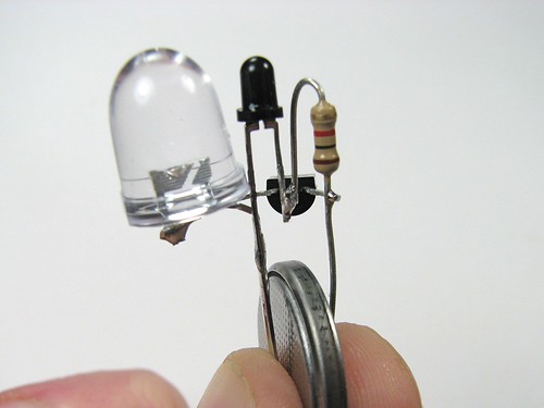
To test the circuit, squeeze the coin cell between these two terminals, positive side goes to the lead touching the resistor. You can’t see the LED on here because these photos were taken with incandescent lighting– it wouldn’t turn on.
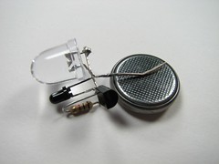
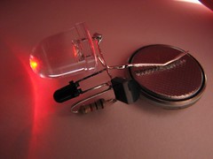
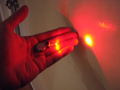
Bending the leads to contact the lithium cell a little more reliably, you can try it out a little more easily. In the photo on the right, I cupped my hand over the circuit– so the LED turned on.
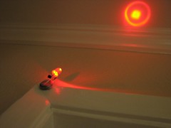
To make this into an actual “throwie,” you still need to add some tape and a magnet, but that’s quite easily done. This one makes a pretty good nightlight attached to the top of a doorframe– when the room lights are off, it shines a bright, bright spot on the ceiling.
Where to go from here? While this little circuit can do something on its own, it would probably also be happy as part of a larger circuit. At a minimum, note that if you work with batteries that have lower internal resistance than the lithium coin cells, you should place an appropriate resistor in series with the battery before trying to operate this circuit– or else you may put too much current through the LED. Certainly, this is one of the easiest and least expensive ways to control an LED with a photosensor. (Unlike, say, this method?) You could also consider crossing it with some more extreme mods, like the
Talkie Throwies that know Morse code, or for more extreme hackers, bagel throwies.
Note added, May 2012:
This set of components works well, and is a pretty neat little dark detector.
We have received hundreds of responses to this article both here in the comments (which are now closed due to abuse) and by e-mail, asking (a) how you would modify this circuit to do X, Y, or Z, (b) whether you can use component THX1138 for the phototransistor, because that’s the only one available on the tropical island where you live, or (c) why your circuit doesn’t work, because you only made two substitutions.
We are, for the most part,unable to respond to inquiries like these. Designing circuits is not always trivial, and we don’t want to give flippant (or worse, wrong) answers, when people are trying to solve problems.
To give the quick set of answers to some of the popular questions:
- This it is a special set of parts that is chosen to work well together, and several simplifications have been made on the basis of which particular components are used– for example, we rely on the internal resistance of the coin cell, so that we don’t need an external current-limiting resistor. Because of this, there aren’t many simple direct substitutions that work well.
- There are plenty of great CdS (“LDR”) phototransistor circuits out there. For better or worse, this is not one of them. (We happen to think betterfor a number of reasons.)
- You can’t just substitute a white (or UV, or blue, etc) LED directly, because there isn’t enough voltage to drive it well. (We did actually show how to do this one– see below.)
- You can’t just substitute 12 V, because the current will be too high, and will blow out your LED. Yes, there are ways to do it, but you have to think it through.
- Some other phototransistors will work, and some will not. If you would like to know which, you can compare their datasheets, or– better yet –just try it!
If you would like to see a couple of other examples of dark-detecting circuits, please see here:
A dark detecting circuit for your pumpkin and a forum post showing how to build this circuit with white LEDs.

Your NPN transistor is in a somewhat odd place; they’re usually "low side" drivers. Is the position it’s in required by the characteristics of the photodiode and circuit?
Is sensitivity adjustable at all? It has seemed to me that a problem with most dark-activated circuits is that they turn on when the room/outside is far from dark, and I end up wasting batteries trying to light up an area that is already quite adequately lit by ‘dusk.’ It’s almost worth throwing a microcontroller at.
Hi Bill,
We do normally use the NPNs as low-sides, of course. This circuit *is* a little bit of an odd ball, designed for simplicity rather than efficiency. I can’t really justify it much better than to say (1) it does work (2) there are a heck of a lot of other ways to make it work as well and (3) compromise is the name of the game here. ;)
The first stage of the circuit is a transistor inverter– using the phototransistor, which pulls the base of the transistor low when the phototransistor turns on. Exactly how far and how fast the voltage at the transistor base drops is determined by the value of the resistor. The transistor can conduct– turn on the LED– only when the base voltage exceeds the sum of the forward voltage of the transistor (Vbe-on) and the LED forward voltage. As long as the phototransistor inverter can pull the transistor base below about 2.5 V, the LED will shut off. So in a sense, we are playing on the characteristics of the components to make this work.
Obviously, you can increase the light sensitivity by increasing the resistor value. The circuit still works okay as you increase the resistance up to, say, 10 k. There is, however, a negative side effect of increasing R. Because the resistance is higher, there is less transistor base current when the LED is on, so the transistor won’t turn on as far, and the LED won’t be as bright. You could compensate by choosing a transistor with much higher gain than the 2N3904 (not saying much, if you know what I mean). In any case, there is a lot of room for improvement. Our default value of 1k is not all that sensitive– might leave your LED on at twilight, so it’s certainly worth playing with.
—
Windell H. Oskay
drwho(at)evilmadscientist.com
http://www.evilmadscientist.com/
I am a total newbie to electronics, and barely know how a transistor works, but I ran across something called a darlington pair. Could you just wire two of those cheap transistors together to increase the gain? Then you could use a larger resistor but compensate for the loss in gain for minimal cost. I don’t know how that would fit into your compact construction, but it’s a thought.
A darlington will not work here– at least if you’re using the 3 V battery like we are. It’s essentially two transistors in series, trading off a higher voltage requirement for higher gain: it takes twice as much voltage to turn on.
A single transistor with higher gain is a better solution if you want better sensitivity. I have not tried it yet, but the 2N5962 looks like an excellent choice– it even comes in the same package ("TO-92") with the same pinout. They are in stock at Mouser now for $0.08 each. =)
—
Windell H. Oskay
drwho(at)evilmadscientist.com
http://www.evilmadscientist.com/
The transistor is in what is called an emitter follower or "common collector" configuration. The voltage on the emitter will "follow" the voltage on the base, but at roughly 0.7V lower voltage. The downside of this is that you are throwing away a lot of voltage – the 1.5V drop across the 1k resistor plus the 0.7V drop of the vbe of the transistor. The circuit might work with other color LEDs if you increase the resistor slightly and use the 3904 to pull down the ground side of the LED, with the anode connected to vcc, like westfw was referring to. In that case you should be able to get up to 2.8V across the diode if the transistor has enough current gain.
I take it back. The follower only loses 0.5V over the common emitter, since the 1k resistor has no current through it when the phototransistor is dark. So maybe the emitter follower is not so bad after all!
I read 50 mV across the 1 k resistor, and slightly over 2 V across the LED. (Not quite fully on; time to order some better transistors.)
—
Windell H. Oskay
drwho(at)evilmadscientist.com
http://www.evilmadscientist.com/
I’m somewhat new to electronics and interested in lighting and LEDs. Question: is there a simple (read: inexpensive, small) that could be added to this project? In other words, for example I want the light to go on for X hours then turn off until the next transition from light to dark. That way the battery doesn’t expire as quickly but it can be used for applications such as Xmas lights, halloween, etc. where it doesn’t need to be on all day (assuming an array of LEDs).
I assume that you meant to use the word “timer” in there somewhere.
You could probably do it by adding a capacitor, resistor, and diode in the right way, but it does start to get complicated. I would suggest instead making the transition to using a microcontroller. Start here for inspiration.
My approach would be to use a single tiny AVR, and to use the LED as the photosensor for it. The internal timer on the AVR is sufficient for whatever timing needs you have.
—
Windell H. Oskay
drwho(at)evilmadscientist.com
http://www.evilmadscientist.com/
next step: most folks arent aware that basic led’s are themselves photo detectors (in addition to being photo emitters)…hook one up to a sensitive DMM meter to prove it for yourself.
The challenge: if we substitute an led as the detector (let’s say because our junkbox has leds, resistors, and transistors lying around…but dont have any photo transistors)…can we redisign a simple circuit that operates in a similar manner using two LEDs…one for input, the other for output?
A photodiode on its own doesn’t generate much current; LEDs tend to be smaller and generate even less. The beauty of the phototransistor is that it includes the gain that you need to use that tiny current. You can do the same thing by providing an external transistor for the photodiode (or LED) of course… just one more component.
—
Windell H. Oskay
drwho(at)evilmadscientist.com
http://www.evilmadscientist.com/
If you happen to have a microchip around, just that and an LED and a battery will do.
Similar to those LED throwies that have the microchip sitting on the LED’s legs, the same concept could be used.
Have the microchip reverse bias the LED and then swap the anode to be a high impedance input, then loop over checking the value of the LED, it should go high after x loops, depending on how much light lands on the LED.
In the dark, it will take longer (less light -> less photocurrent) so if you count how many loops it took and then only turn the LED on when the loop count is above the threshhold, you could have the same circuit in only 2 components and the battery.
However, if it got very dark the flashing off when the LED is reverse biased would probably take long enough that it would be noticeable – you could try having a maximum the loop will go up to before it assumes it’s dark and stops there.
I wondered why I was getting more traffic on Flickr – thanks, EMSL!
Steve/Irregular Shed
Could you combine this with the joule thief? Would you just insert this circuit into the joule thief circuit as if it was an on/off switch? Or would the way this circuit plays with current not make it a switch per se? I’m a mechanical with a limited electronics knowledge that doesn’t extend too far past the following a recipe stage. I could guess that the low current ‘off’ state of this circuit might get boosted by the joule thief and end up with an always on circuit maybe.
I’m thinking it’d be nice to use up old batteries in night light or xmas decoration duty. I’ve got a couple outdoor wreaths that would look good with a few led ‘berries’ on them at night.
It is possible.
I *think* I know an easy way to make it work, but I don’t have the parts with me to check. So… I shouldn’t say anything, except that there is more than one way to make it work. =)
—
Windell H. Oskay
drwho(at)evilmadscientist.com
http://www.evilmadscientist.com/
ye i guess u could this is wat u would have to do instead of the 3 volt battery u would hook up what ever size battery u got just as long as it is 1.5 volts then you take off the led and make sure the polarity is correcct , have to connect it instead of the battery in the joule theif
The problem I see with this circuit is that when the photocell is turned on, the full 3.6V is across the 1k resistor, which draws 3.6/1000 of an amp or 3.6 milliamps. This is not as much as the LED, but it’s a substantial part of what the LED draws, so the battery will last somewhat longer, but will still go dead soon in a few days.
But by making a few changes, the battery life can be extended a lot more, to months. One way is to replace the 2N3904 with a 2N7000 enhancement mode MOSFET. This is a few cents more than the 2N3904 if you buy them from FairchildDirect.com or Mouser. Instead of a 1k, replace the resistor with a 1 meg resistor. The current drain will then be a thousand times lower when it’s off. The 2N7000 requires more voltage at the gate, so to solve this, the LED must be moved from the emitter and put in the ‘collector’ which is called the drain in the 2N7000 (the pinout is the same as the 2N3904). Since the gate of the 2N7000 draws almost no current, you can use something other than a phototransistor. A LED might work instead. But since it can generate a voltage when it’s illuminated, the LED may have to be put in backwards to _reduce_ the voltage at the gate.
Another way is to add another transistor to reduce the base bias needed. I’ll have to write up a blog on this later (it’s at watsonseblog.blogspot.com). But if you’ve experimented with the 2N3904 or other transistors, you will just *LOVE* the 2N7000! The gate is so sensitive that you can turn it on with just a touch. And since it is almost infinite input impedance, the gate can be used to detect all sorts of things like E fields. But for timers it’s incredible because you can turn it on for minutes or more with a several megohm resistor and a 100uF capacitor. It’s like a super transistor.
Later…
Obviously a FET is a better way to go, and I even considered the 2N7000, but I didn’t have any at home when I built this. (It really was a five minute project. Even as far as NPNs go, the 3904 is not a particularly good choice, as we discussed earlier– but it *does* work, and it is very common.) At some point I’ll write up a few other variations on this– including the joule thief version.
In any case, the efficiency of the circuit as drawn is not as bad as you claim, nor is the lifetime of the circuit you describe as good as you claim.
First point: When it’s “off” it’s drawing 1.5 mA, not 3.6 mA. Because this is *not* a FET, the on-state resistance really is not zero, and the maximum current through the resistor is lower than you claim. Also, it’s a 3 V battery — NOT 3.6 V– , so the maximum current that you could get, even with an ideal FET, is 3 mA, not 3.6. The phototransistors vary in their maximum on-state collector current, where the poorest bin has a maximum of 1.2 mA. Mine are from Digi-Key and aren’t relabeled as to what bin they are from, but under bright light, the highest current that I was able to measure through the resistor was 1.5 mA, as stated in the article.
Second point: Your claim about extending the lifetime to months does not make sense. In this version of the circuit, the “off” current is 1.5 mA, ten percent of the 15 mA that it draws while on. Now matter how you cut it, the power consumption is still dominated by the amount that it uses while the LED is on– eliminating the small amount used in the daylight will not cause the lifetime to dramatically increase. You know as well as I do that the only way to dramatically increase the lifetime would be to dramatically decrease the average power consumption while the LED is on.
—
Windell H. Oskay
drwho(at)evilmadscientist.com
http://www.evilmadscientist.com/
I’m sorry, my mistake. I read that the coin cells were from Ebay, so I got on Ebay and looked at some of the offers there. For some reason, I got the impression that they were 3.6V. But I just got through reading the specs (I googled CR2032 datasheet) and it said that the V was 3V. This one, or any other similar: data.energizer.com/PDFs/cr2032.pdf
I’ll address the other points in my Jan 8, 2008 blog at watsonseblog.blogspot.com.
Anyone willing to post some specifics about parts to order, say from mouser or fairchild? When I search those part numbers, I get no fewer than 10 + choices each.
Thanks in advance.
Super Noob
Which change will it be in the circuit if we want more leds to light? Because i can’t find the phototranzistor can i put a photodiode?and if yes which one?
Hmm. Looks like you might be redesigning this circuit from scratch!
—
Windell H. Oskay
drwho(at)evilmadscientist.com
http://www.evilmadscientist.com/
As I was trying to get the components to build this I wasnt able to find LTR-4206E and instead I bought BSP 103-2 which works but only when it is near a bright light.
Any ideas anyone? I would like to have it really sensitive, so if anyone can help me I woould appriciate it.
Thanks in advance.
Do you know what kind of device the BSP 103-2 is?
I don’t see any datasheet around for anything similar sounding except the BSP102– which is a mosfet, not a phototransistor.
—
Windell H. Oskay
drwho(at)evilmadscientist.com
http://www.evilmadscientist.com/
I used a 5mm phototrans from radio shack. The only one avaliable… Don’t know the part number. It was clear not dark. Also switched to a 100k resistor and bumped up the volts to +5. Make sure you have the polarity right on the phototrans. Mine would work reversed but was significantly less sensitive. Took me days to figure that one out. Configured that way it and correctly biased, it is SUPER sensitive. I used it in conjunction with another NP3904 transistor as sort of a Darlington pair to saturate the base voltage. It works great as a dusk to dawn LED solar charging night light thingie. I can light a candle across the room and point the photo trans at it and it emulates the candle flame… Fascinating effect.
Nice,
still no reply?!
I wasnt able to find that Phototransistor LTR-4206E here and this one which I have needs to real close to light if I want LED to be off.
Can I make phototransistor to be less/more sensitive?
please help me guys
Thanks
I replied last time, and I’ll reply again, perfectly clear: No one will be able to help you out with your particular case if you don’t provide sufficient detail.
You might also consider reading the other comments for discussions of ways to change the sensitivity, you know.
—
Windell H. Oskay
drwho(at)evilmadscientist.com
http://www.evilmadscientist.com/
Hi, thanks for the circuit. With a little trouble I was able to get it to work. I spent an embarrassing amount of time trying to make it work in my florescent lit office before realizing the LTR-4206E doesn’t turn off with florescent lights.
I have a couple of questions. Sorry if they sound dumb, but I’m a bit new to electronics.
1. Photo active components like photoresistors, photodiodes, phototransistors, etc – they all seem to be dark off and light on. Am I correct? Is there such a thing as a dark on light off device? Would such a device be more efficient in this case? Would the current to turn the transistor on be less than "wasted" current in keeping it off?
2. Is there a good reference for transistors, telling what base current is necessary to achieve what collector/emitter current with efficiency, loss, etc?
3. Transistors switch and amplify current, right? Not voltage? The reason I’m asking is I’m wondering how hard it would be to make this device with an LED series array.
Thanks.
Hello all,
I realize that this may be a somewhat elementary question for most of you, but Id appreciate any and all answers to it as this circuit could be really useful to me. my question is simply if its possible to use this same circuit when powering 3-6 LEDs from a 3v DC power source. If not, is there a way to modify it so that it can perform under those conditions?
Thanks,
michael
yes you can.
simply wire all of those led’s in parallel.
I got all the components that are needed for the project, but at the moment to do that doesn’t work because the LED is always on, I would like to know why.
I appreciate any help
Are all the components exactly the same as we’re using?
—
Windell H. Oskay
drwho(at)evilmadscientist.com
http://www.evilmadscientist.com/
Yes
Even I test all components with a multimeter and all are ok.
If you know how to test a transistor with a multimeter well enough to be sure that it’s good, then (1) I’m impressed (2) surely you can find the problem in your circuit without our help!
—
Windell H. Oskay
drwho(at)evilmadscientist.com
http://www.evilmadscientist.com/
Well thanks, sorry for any inconvenience.
My multimeter is the MUL-040 from STEREN.
What would work for both sun and florcent (CPF) lights
Thanks for the idea and it does with with a standard flashlight
Just use a phototransistor without the dark (visible-blocking) lens.
—
Windell H. Oskay
drwho(at)evilmadscientist.com
http://www.evilmadscientist.com/
Thanks. I ordered some and will write back with my findings.
How would you do this wiht a PNP transistor? Like the 2n3906?
who invented the dark detector circuit and when was it invented?
How would the circuit be diffrent if we had a photoresistor, instead of a phototransistor ?
thanks
how can i make dark/light detector using a general purpose transistor?
I’ve been looking for these parts on radioshack, and i wanted to know if i can use radioshack part 276-142 in this project. Is 276-142 the same thing as the phototransistor used in this project?
Not exactly the same, but I would guess that it would work.
—
Windell H. Oskay
drwho(at)evilmadscientist.com
http://www.evilmadscientist.com/
i have aL14F1 photo transistor can anybody tell me how to connect it and the details of the pins [ i dont know which one is emmiter n which one is collector] … plz
You might try looking at the datasheet for it.
—
Windell H. Oskay
drwho(at)evilmadscientist.com
http://www.evilmadscientist.com/
i connected the whole circuit …… i put a L14F1 photoresistor .. but the led turns on even in day time … i checked the connections all were fine … plz help ..
That’s a very different type of phototransistor that you’re using– a darlington –I’m not suprised that it behaves differently..
—
Windell H. Oskay
drwho(at)evilmadscientist.com
http://www.evilmadscientist.com/
how do i fix a darlington in the circuit ?????? L14F1
What kind of changes might need to be made to this circuit if I want to use white LEDs? I think that they require a bit more voltage. Could I make a simple part substitution and be able to use white?
Thanks,
Scott
See this post in the forum.
—
Windell H. Oskay
drwho(at)evilmadscientist.com
http://www.evilmadscientist.com/
i have just started electronics and this is the first project i have made. Is there anyway of making it more sensitive to light?
Yes; you might want to start with the method that we mentioned above.
—
Windell H. Oskay
drwho(at)evilmadscientist.com
http://www.evilmadscientist.com/
Hey man, thanks for this, it’s exactly what I was looking for… I was wondering though, could you show me how I could add a function to fade the LED in and out slowly over 5 second intervals (much like the macbook pro’s sleep light when the display is closed)?
Would it be as simple as putting a capacitor from emitter to ground?
hi,
great article, im in australia and bought this phototransistor
http://jaycar.com.au/productView.asp?ID=ZD1950&keywords=phototransistor&form=KEYWORD
in replacement of the one used in ur circuit, i was told that it would work in the same way, but after putting it all together it doesnt work.
can this phototransistor work in this circuit?
they don’t stock any other phototransistors apart from that, i also replaced the LED for this
LED 5MM DIF RED 12MCD.
would that cause any problems?
thanks
i am planning to design a switch that will automatically turn on our fluorescent lamp using this dark detecting led……. can i replace the led with a relay which i will connect to our plug? is it possible to operate the switch if the only part that is exposed is the photo transistor???
Yes, a solid-state relay that has a red/ir LED as its front end can be substituted for the red LED in this project.
—
Windell H. Oskay
drwho(at)evilmadscientist.com
http://www.evilmadscientist.com/
hello can you please help me in my line sensor circuit diagram??? can i ask a simple circuit on how to make a line following sensor using these components: IR (infrared), 74LS14 Schmitt Trigger, resistors, and a PN268Q transistor,…. please help me…
and you please send it to my email add: cmpemacky@yahoo.com
thank you very much…
I’m thinking phototransistor != photoresistor. You at least need to make sure the logic works out. Sounds like it isn’t.
Hi, I drive 1 white LED from a 15volt supply using a 680Ohm resistor. Will I be able to add this circuit to my existing setup? and if so what modifications do I need? Thanks for your help.
Does this project use a 3.6v or a 2.6v led? I cannot find a 3.0v
It uses a 3 V battery, just like it says. This is a very common type.
—
Windell H. Oskay
drwho(at)evilmadscientist.com
http://www.evilmadscientist.com/
READ. LED
i would like to extent this concept of dark-detecting light bulb with abt 10 leds on 230v ac mains. similar simple circuit was found here:
http://www.instructables.com/id/light_detector_no_microprocessors_just_simple_el/
what i propose to do is this, for the instructables version:
1. connect 10 leds (5mm) in series (+ of one to – of other)
2. connect this to a diode bridge rectifier (4007?).
3. connect a .22uF 400 volt capacitor and a 1k resistor to the ac portion of the diode bridge
will it work ?? what else is possible for ac mains on evilmadscientist circuit ??..
reg
ketan
If you even think about asking "will it work," with respect to a project involving AC mains, you *do not* know what you are doing well enough to do it safely.
Get professional help; mains power can kill you and you don’t want to be fooling around with it.
—
Windell H. Oskay
drwho(at)evilmadscientist.com
http://www.evilmadscientist.com/
Your concern on the safety aspect, while dealing with AC Mains is very genuine. There are thousands, if not hundreds of thousands, who visit your site – probably for the same answer that i am looking for (Light detector sensor search on google is in millions !).
So let me re-phrase my comment – Can you provide a circuit for light/dark sensing simple circuit for ac mains, the way you have posted for 3vDC ? You can highlight the safety fact, as always.
reg
ketan
i need all the datasheet for my subject.
why not use a photo cell instead of the LTR-4206E? it works mush better and is far more sensitive.
>why not use a photo cell instead of the LTR-4206E?
That’s a different type of element, and we did discuss the reason not to use one.
—
Windell H. Oskay
drwho(at)evilmadscientist.com
http://www.evilmadscientist.com/
would it work just as well though?
Scott
I didn’t get why don’t we use LDRs they are cheaper and easier to use and find. I made the same system with a LDR and I used a phototransistor for a normal one (It has 3 legs).
From the article:
"Photoresistors are reliable and cost about $1 each, but are going away because they contain cadmium, a toxic heavy metal whose use is increasingly regulated. "
What will be the circuit if you input an AC voltage?
pjayfrey@yahoo.com
Hi all. Can use this scheme for 20 diodes operating at 12 volts.
For those of you looking to change the sensitivity:
Instead of just the phototransistor, replace it with a PNP transistor and connect the phototransistor between the base and ground.
With this modification, you can get it to where it only turns on when it’s fairly dark.
d/n
Two questions for you!
1. Could the 2032 coin cell be replaced with 2 AA cells in series?
2. Could numerous LED’s be run in parallel without any change to the setup, assuming the LED’s have smiliar fV?
Thanks!
Steve
>1. Could the 2032 coin cell be replaced with 2 AA cells in series?
Maybe; you might need a small extra resistor in series, though.
>2. Could numerous LED’s be run in parallel without any change to the setup, assuming the LED’s have smiliar fV?
Yes. fV is never exactly matched; better to give each its own small-value series resistor, too.
Windell H. Oskay
drwho(at)evilmadscientist.com
http://www.evilmadscientist.com/
Hi, I need to create a magneto-opto-electronic switch for a science project – – and when I saw your schematic and application I thought WOW, how totally simple.
Some background:
When my son points a strong magnetic array at a simple compass hidden behind a rock at 4 feet away – – – the compass needle turns enough to momentarily break the pinhole LED light source beam (“break beam”) we will have shining through the plexiglass compass on to the phototransistor on the other side – – so then a 26 LED array gets activated (rather than just your simple red LED as in your schematic) – – – I measured the current drain of the 26 LED array at about 200 milliamps at 4.5 volts (3 AAA batteries) so I need to add a little micro power relay – – – any suggestions ? I thought an IFR 510 MOSFET but I dunno what pins go where . . .
I figure a tiny piece of aluminum foil pierced by a needle is a good enough pinhole source.
Questions:
1) Couldn’t I just I drive your entire circuit with a 4.5 volt battery pak (3 – AAA batteries) instead of your 3V button battery ? This would be the same battery pak that drives the intended output – – a 26 LED array that I measured draws about 200 milliamps.
2) I need the entire circuit to react FAST – – do you think it would react fast enough to show the 26 LED array flash momentarily everytime the compass needle turns over the pinhole LED light source ?
Right now I’m using 2 hair thin copper wires as the switch – – – and when they get “bumped” they do allow the 26 LED array to flash momentarily.
I bought the 26 LED array flashlight thingy at Harbor Freight recently.
3) Couldn’t I substitute an adjustable 100 to 1000 ohm pot resistor where your 1K resistor is an use that to adjust sensitivity – – or would a pot resistor draw excessive energy over your fixed resistor ?
This website shows a schematic that works, but is probably above my abilities to figure out the schematic and solder it up correctly.
http://home.cogeco.ca/~rpaisley4/PhotoDetectors.html
If spending a few pennies more and not worrying about any possible additional current drain in the resting state is no problem . . .
I think I found a solution that does not involve a microelectronic relay for the magneto-opto-electronic switch . . .
Why not just replace your existing 2N3904 transistor with a beefier PN2222A ?
Am I reading the specs right ? This PN2222A should be able to easily handle a 200 milliamp load at 4.5 volts . . .
http://www.fairchildsemi.com/ds/PN/PN2222A.pdf
Just replacing the transistor with one rated for higher current won’t change the voltages that it operates at. I’m not sure in what sense this is a solution.
Windell H. Oskay
drwho(at)evilmadscientist.com
http://www.evilmadscientist.com/
It would be much easier to start over from scratch, with your actual requirements, than to try and modify our circuit in the many ways that you suggest.
If you wanted an easy way to use this exact circuit to switch a higher load, use a solid-state relay with "LED type" input in place of our red LED.
Windell H. Oskay
drwho(at)evilmadscientist.com
http://www.evilmadscientist.com/
I just wanted to know that by placing same phottransistor and changing resister and placing a bulb of 40v with led can we get same result . if yes what should be the resistor value or any more changes we have to make in it so that we can make a bulb to glow when sunlight goes off. please reply to my mail id mrraghavendra2987@rediffmail.com with circuit
How long will the battery last? How could this be modified so when the light is on in the room, the LED turns on? I want to create a sensor that mounts on the bathroom door and when the light/vent fan is on while it is occupied. The LED lights up announcing the room is occupied.
I built this circuit last night using the correct transistor, a red LED and a 1k ohm resister but with a different phototransistor. The phototransistor was the only one I could find at ‘The Shack’ and was an IR sensing phototransistor. But in theory, this still should have worked… Can you provide any insight in to why or would you need more details? The LED always turns on no matter what situation it is in. When the battery touches the wires it kicks on right away. I’m assuming it’s more of a functional issue rather than a circuit issue because the circuit seems to be exactly what this page describes just with an IR sensing phototransistor instead of the one you called for. One thing I do know, it turns on whether there is IR in the room or not. I got my IR webcam out and tested.
Thanks,
A
I used Radioshack part 276-145.
This question still stands.. .Any idea why it may not be working?
For starters, that’s not a visible-light blocking phototransistor. If you want it to *only* detect infrared, you’ll have to block visible light.
Windell H. Oskay
drwho(at)evilmadscientist.com
http://www.evilmadscientist.com/
For the record, I’ve never heard of this part working for this circuit. Not sure why you assume it would, and there’s no datasheet to compare to. Its gain and sensitivity regions may be very different.
(Your approach is a little bit like saying "I replaced the resistor with another type. I don’t know what type. Why doesn’t it work?")
Windell H. Oskay
drwho(at)evilmadscientist.com
http://www.evilmadscientist.com/
Thanks for your reply. I assumed it would work because I’m a noob lol. I couldn’t find the correct part and both said "Phototransistor" so I assumed that would work. I had tried blocking ALL light and still had no success in the LED going off so I’m assuming it’s something more related to the part’s specs. Guess, if I want this to work, I should just stick with the right parts…
Hey guys,
just a quick thought, wouldn’t you have to place the photocell and the LED in such a way that the LED does not cast light on the photocell when on? I know that sounds obvious, but could be problematic, especially with diffused LED’s. In this example you used waterclear, which shines a beam away from the device, but a diffused led would cast light onto the photocell, in the current setup that you have.
Oscar
It’s not a photocell, it’s a phototransistor. And, it’s a phototransistor that only sees infrared light (such as that in sunlight)– it can’t see the red LED.
Windell H. Oskay
drwho(at)evilmadscientist.com
http://www.evilmadscientist.com/
Right, sorry. Ok, thanks, but what components are available that can do the same thing, but for light in the visible spectrum (thinking about adapting this and hacking it onto a ThinkGeek Eviltron (a small device that emits scary sounds) so that it is only activated when the lights go off and the victim goes to sleep)
sorry…just asking…
can i implement this simple circuit to my home’s back site?
It’s not at all clear what you’re asking.
Windell H. Oskay
drwho(at)evilmadscientist.com
http://www.evilmadscientist.com/
Hey Windell – Thanks for sharing this genius and elegant solution.
Quick question for you. I would like to try this with UV LEDs instead. I have seen 8mm UV LEDs for cheap that are 3V and 100ma. Seems like 2-3x more current than a RED LED…. Will the phototransistor switch still work? Also, I’m assuming that the CR2032 battery will last approx 1/3 as long as with the lower current-drawing RED led, correct? Thanks for your help…. Hoping to implement this in a large scale art project,
alt12
>Quick question for you. I would like to try this with UV LEDs instead.
>I have seen 8mm UV LEDs for cheap that are 3V and 100ma.
>Seems like 2-3x more current than a RED LED…. Will the
>phototransistor switch still work?
This is *not* a quick question. A UV LED rated as 3V, 100 mA begins to emit light at 3 V, and can handle up to 100 mA– which it won’t get until you feed it close to 4 V.
This circuit, as designed, only works with red, orange, or yellow LEDs. It will not work with blue, white, or UV LEDs, which require a higher voltage to operate. See this forum post on how to make it work with a white (or UV) LED:
http://www.evilmadscientist.com/forum/viewtopic.php?showtopic=450
Windell H. Oskay
drwho(at)evilmadscientist.com
http://www.evilmadscientist.com/
Ok, thanks for the response. I guess it wasn’t such a quick question :) I will take a look at that forum. What about the amperage issue? Will a UV LED run for significantly less time from a CR2032 versus a red or green LED? I read on the instructables.com listing for the LED throwie that a CR2032 can run an LED for a week or more. But from the CR spec sheet, it only has 240mAh and if its a 30ma green LED, why would it last more than say 8 hours? thanks for your help
alt
For a detailed analysis of the throwie battery issue, you might take a look at our article on the subject:
[link:http://www.evilmadscientist.com/article.php/throw Some thoughts on throwies]
What determines when the transistor is off or on?
Just finished this project with slightly different way, I used round project board from radio shack.
Turned and twisted some leads to complete circuit,and got disappointed when led remained lit.Well
good thing i read pretty much all Q and A from experts and clicked in my mind that this will work only in sunlight or Incandescent light.I tried with flash light and it worked as it suppose to.Well thanks to every one.
Curious why my set of same circuit cant off during the day. I’m using 2N3904 -703. Is there any difference?
Any two 2N3904’s work the same way.
Windell H. Oskay
drwho(at)evilmadscientist.com
http://www.evilmadscientist.com/
But how come my LED didn’t turn of even under sunlight. My power supply from 5V regulator.
This circuit does not work from 5 V; it works exactly as described, and not with modifications like that.
Windell H. Oskay
drwho(at)evilmadscientist.com
http://www.evilmadscientist.com/
will itt work with 12 volt???
Hi
i need to make a dark activated blinking LED circuit powered by 6V and should have 6 LEDs
it should blink at a frequency of 1hz
hope you could help me by sending the circuit diagram
yours sincerely
Supratik
secondary 3
singapore
I’m a newbie. My LED still lights up faintly all the time. i used components i already had: a 16-32K LDR and a BC548B transistor. ( I was going to make a circuit with a potentiometer in it). What do i need to do to rectify – start over with same components as yours?
Lou
This is not an LDR circuit, it’s a phototransistor circuit. These aren’t similar components, and you shouldn’t expect them to work in the same way.
Windell H. Oskay
drwho(at)evilmadscientist.com
http://www.evilmadscientist.com/
Hi all. I make this scheme, but with IRE 5(phototransistor),BC 548, White LED +1k res. on 12V. And LED lights permanently. What is wrong?
Can you put an LDR instead of a phototransistor? ..the wiring would be the same?
As per above,
"This is not an LDR circuit, it’s a phototransistor circuit. These aren’t similar components, and you shouldn’t expect them to work in the same way."
Thank you! I have created a modified version, I called it: Iron Droid. It is not finished though, but it worked very good. Thank you for your article!
The YouTube link for the video of my prototype is:
http://www.youtube.com/watch?v=kmVoWFhIAVM
I can send you my powerpoint presentation (if for a class) if you want to look at my modification.
Thank again!
Thank you. This one is really simpliest circuit for dark detection. Just used LPT 80A phototransistor and connected a 220R between 2N3904‘s emitter and LED. Works perfectly.
i’m not able to get a LTR-4206E phototransistor. can i have any equivalent for that?
I’ve built, taken apart and re-built this circuit five times, but my circuit keeps acting the opposite of what it’s supposed to: LED turns ON in light, OFF when dark. What am I doing wrong?
Then you apparently haven’t built the exact same circuit. Carefully ask yourself this: what have you changed?
Windell H. Oskay
drwho(at)evilmadscientist.com
http://www.evilmadscientist.com/
Figured it out: I had the battery and LED polarities reversed, everything else was correct. This changed the basic functioning of the circuit to the opposite. Maybe someone else can use this?